
NI 43-101 Technical Report
Definitive Feasibility Study and
Updated Mineral Reserve and Mineral Resource Estimates
Copper World Project
Pima County, Arizona, USA
Effective Date: September 30, 2026
25 York Street, Suite 800
Toronto, Ontario
Canada M5J 2V5
Prepared by:
Olivier Tavchandjian, P. Geo., Hudbay Minerals Inc.
 |
CAUTIONARY NOTE REGARDING FORWARD-LOOKING INFORMATION
This Technical Report contains forward-looking information within the meaning of applicable Canadian and United States securities legislation. All information contained in this Technical Report, other than statements of current and historical fact, is forward-looking information. Often, but not always, forward-looking information can be identified by the use of words such as "plans", "expects", "budget", "guidance", "scheduled", "estimates", "forecasts", "strategy", "target", "intends", "objective", "goal", "understands", "anticipates" and "believes" (and variations of these or similar words) and statements that certain actions, events or results "may", "could", "would", "should", "might" "occur" or "be achieved" or "will be taken" (and variations of these or similar expressions). All of the forward-looking information in this Technical Report is qualified by this cautionary note.
Forward-looking information includes, but is not limited to, the results and findings of the 2026 Definitive Feasibility Study, including the production, operating cost, capital cost and cash cost estimates, the projected valuation metrics and rates of return, the cash flow and EBITDA projections, statements regarding the anticipated permitting requirements and project design, including processing and tailings facilities, metal recoveries, mine life and production rates for the Project, the expected funding requirements for the Project, the potential to further enhance the economics of the Project and optimize the design in the future, including with respect to the potential extension onto federal lands, as part of the Extension Case described herein and the potential to advance and possibly implement the concentrate leach option, the possibility of extending the life of the mine, and the expected social and environmental benefits of the Project, including with respect to the local communities and stakeholders. Forward-looking information is not, and cannot be, a guarantee of future results or events. Forward-looking information is based on, among other things, opinions, assumptions, estimates and analyses that, while considered reasonable by us at the date the forward-looking information is provided, inherently are subject to significant risks, uncertainties, contingencies and other factors that may cause actual results and events to be materially different from those expressed or implied by the forward-looking information.
The material factors or assumptions that Hudbay identified and were applied by Hudbay in drawing conclusions or making forecasts or projections set out in the forward-looking information include, but are not limited to:
• the ability to obtain and maintain all required permits and authorizations to develop and operate the Project in accordance with the Base Case presented in this Technical Report;
• the accuracy of the feasibility and pre-feasibility estimates of costs presented in this Technical Report;
• no capital cost escalation on the growth capital presented in this Technical Report due to inflationary or other factors;
• if a decision is made at a future date to pursue the Extension Case, the ability to obtain and maintain all additional permits and authorizations required to develop and operate the Project in accordance with the Extension Case presented in this Technical Report;
• the feasibility of aspects of the Base Case and Extension Case that to date have been completed to pre-feasibility levels;
• no delays or disruptions due to litigation challenging the permitting requirements or permits for the Project and no significant unanticipated litigation;
|
• the potential implementation of the concentrate leach option;
• the ability to acquire additional small parcels of land within Copper World's property boundary;
• the success of exploration and development activities;
• the accuracy of geological, mining and metallurgical estimates;
• anticipated metals prices and the costs of production;
• the supply and demand for metals the Project produces;
• the supply and availability of groundwater and surface water;
• the supply and availability of all forms of energy, fuels and other consumables at reasonable prices;
• no significant unanticipated operational or technical difficulties;
• the availability of additional financing, if needed;
• the stability of the joint venture partnership with Mitsubishi;
• the ability to complete Project targets on time and on budget;
• the availability of personnel for exploration, development and operational projects and ongoing employee relations;
• the ability to maintain good relations with the local communities, including the neighbouring communities and local governments in Arizona;
• no significant challenges with Pima County or other stakeholders at Copper World;
• no significant unanticipated events or changes relating to regulatory, environmental, health and safety matters;
• no contests over title to Hudbay's properties, including as a result of rights or claimed rights of Indigenous peoples or challenges to the validity of its unpatented mining claims;
• the ability to receive the upfront stream deposit of $230 million from Wheaton Precious Metals at the commencement of construction in accordance with the amended and restated precious metals purchase agreement;
• no disputes in respect of agreements that were previously entered into by Augusta Resource Corporation ("Augusta") in respect of the former Rosemont Copper Project;
• certain tax matters, including, but not limited to the mining tax regime in Arizona; and
• no significant and continuing adverse changes in general economic conditions or conditions in the financial markets (including commodity prices and foreign exchange rates).
The risks, uncertainties, contingencies and other factors that may cause actual results to differ materially from those expressed or implied by the forward-looking information may include, but are not limited to, risks generally associated with the mining industry and the current geopolitical environment, including future commodity prices, currency and interest rate fluctuations, water availability, energy and consumable prices, supply chain constraints and general cost escalation in the current inflationary environment, risks related to project delivery and financing; ongoing and potential litigation processes and other legal challenges that could affect the Project (including in respect of any future authorizations or agreements that may be required), risks related to acquiring additional small parcels of land within Copper World's property boundary, risks related to political or social instability and changes in government and government policy, risks related to changes in law, risks in respect of community relations, risks related to contracts that were entered into by Augusta in respect of the former Rosemont Copper Project, uncertainties related to the geology, continuity, grade and estimates of mineral reserves and resources, and the potential for variations in grade and recovery rates, risks related to the timing and implementation of the concentrate leach option, climate change related risks and uncertainties, as well as the risks discussed elsewhere in this Technical Report, under the heading "Risk Factors" in Hudbay's most recent annual information form and under the heading "Financial Risk Management" in Hudbay's most recent annual management's discussion and analysis, copies of which are available on Hudbay's SEDAR+ and EDGAR profiles. Should one or more risk, uncertainty, contingency or other factor materialize or should any factor or assumption prove incorrect, actual results could vary materially from those expressed or implied in the forward-looking information. Accordingly, you should not place undue reliance on forward-looking information. Hudbay does not assume any obligation to update or revise any forward-looking information after the date of this Technical Report or to explain any material difference between subsequent actual events and any forward-looking information, except as required by applicable law.
|
Cautionary Note Regarding NI 43-101
The scientific and technical information contained in this Technical Report has been approved by Olivier Tavchandjian, P. Geo, Hudbay's Senior Vice President, Exploration and Technical Services. Mr. Tavchandjian is a qualified person pursuant to Canadian Securities Administrators' National Instrument 43-101 - Standards of Disclosure for Mineral Projects ("NI 43-101").
This 2026 Definitive Feasibility Study is the current NI 43-101 Technical Report in respect of all of the mineral properties that form part of the Project and supersedes and replaces the 2023 PFS (as defined herein) in its entirety.
Readers should be advised that this Technical Report presents certain material information associated with the Project based on pre-feasibility level work only, which carries more risk and uncertainty than work completed to a feasibility study level. In addition, the Extension Case mine plan would require Copper World to apply for and obtain federal permits prior to Year 10 and is not the selected development option in this Technical Report. The Extension Case is intended to illustrate the full potential of the Project and in the opinion of the author constitutes other relevant data that should be included in this Technical Report. The Extension Case is based on measured and indicated mineral resources that are not mineral reserves.
Mineral resources that are not mineral reserves do not have demonstrated economic viability.
Non-IFRS Financial Performance Measures
This Technical Report contains certain non-IFRS financial performance measures. Cash cost and sustaining cash cost per pound of copper produced are shown because Hudbay believes they help investors and management assess the performance of its operations, including the margin generated by the operations and Hudbay. Unit operating costs are shown because Hudbay believes they help investors and management assess the cost structure and margins that are not impacted by variability in by-product commodity prices. EBITDA is shown to help users analyze Hudbay's results and to provide additional information about the company's ongoing cash generating potential in order to assess Hudbay's capacity to service and repay debt, carry out investments and cover working capital needs.
|
These measures and any other non-IFRS financial performance measures used herein do not have a meaning prescribed by IFRS and are therefore unlikely to be comparable to similar measures presented by other issuers. These measures should not be considered in isolation or as a substitute for measures prepared in accordance with IFRS and are not necessarily indicative of operating profit or cash flow from operations as determined under IFRS. Other companies may calculate these measures differently. For further details on these measures, please refer to Hudbay's most recent management's discussion and analysis, available on SEDAR+ at www.sedarplus.ca and EDGAR at www.sec.gov.
Cautionary Note to United States Investors
This Technical Report has been prepared in accordance with the requirements of the securities laws in effect in Canada, which differ from the requirements of United States securities laws. Canadian reporting requirements for disclosure of mineral properties are governed NI 43-101. For this reason, information contained in this Technical Report in respect of the Project may not be comparable to similar information made public by United States companies subject to the reporting and disclosure requirements under the United States federal securities laws and the rules and regulations thereunder. For further information on the differences between the disclosure requirements for mineral properties under the United States federal securities laws and NI 43-101, please refer to Hudbay's most recent annual information form, a copy of which has been filed under Hudbay's profile on SEDAR+ at www.sedarplus.ca and Hudbay's most recent Form 40-F, a copy of which has been filed on EDGAR at www.sec.gov.
|
Signature Page
This Technical Report titled "NI 43-101 Technical Report, Definitive Feasibility Study and Updated Mineral Reserve and Mineral Resource Estimates, Copper World Project, Pima County, Arizona, USA", dated October 20, 2026, and effective as of September 30, 2026, was prepared under the supervision and signed by the following author:
Dated this 20th day of October, 2026.
/s/ Olivier Tavchandjian
Signature of Qualified Person
Olivier Tavchandjian, P. Geo.
Senior Vice President, Exploration and Technical Services
Hudbay Minerals Inc.
|
Table of Contents
| 1 Summary | 1-1 |
| 1.1 Introduction | 1-1 |
| 1.2 Property Description & Location | 1-2 |
| 1.3 Geological Setting & Mineralization | 1-4 |
| 1.4 Deposit Types | 1-4 |
| 1.5 Exploration | 1-4 |
| 1.6 Drilling, Sample Preparation, Analytical Procedures & Data Validation | 1-5 |
| 1.7 Mineral Processing & Metallurgical Testing | 1-5 |
| 1.8 Mineral Resource Estimates | 1-7 |
| 1.9 Mineral Reserve Estimate | 1-10 |
| 1.10 Mining Methods | 1-11 |
| 1.11 Project Infrastructure | 1-14 |
| 1.12 Marketing | 1-15 |
| 1.13 Environmental Studies, Permitting, & Social or Community Impact | 1-16 |
| 1.14 Capital & Operating Costs | 1-18 |
| 1.14.1 Base Case Capital and Operating Costs | 1-18 |
| 1.14.2 Extension Case Capital and Operating Costs | 1-19 |
| 1.15 Economic Analysis | 1-19 |
| 1.15.1 Base Case Economic Analysis | 1-19 |
| 1.15.2 Extension Case Economic Analysis | 1-20 |
| 1.16 Conclusions and Recommendations | 1-22 |
| 2 Introduction and Terms of Reference | 2-1 |
| 2.1 General | 2-1 |
| 2.2 Terms of Reference | 2-1 |
| 2.3 Qualified Person | 2-2 |
| 2.4 Site Visits & Responsibility | 2-2 |
| 2.5 Unit Abbreviations | 2-3 |
| 2.6 Name Abbreviations | 2-4 |
| 3 Reliance on other Experts | 3-1 |
| 4 Property Description & Location | 4-1 |
| 4.1 Location | 4-1 |
| 4.2 Tenure | 4-2 |
|
| 5 Accessibility, Climate, Local Resources, Infrastructure, & Physiography | 5-1 |
| 5.1 Accessibility | 5-1 |
| 5.2 Climate | 5-1 |
| 5.3 Local Resources | 5-2 |
| 5.4 Infrastructure | 5-2 |
| 5.5 Physiography | 5-3 |
| 6 History | 6-1 |
| 6.1 Helvetia Mining District (1875-1973) | 6-1 |
| 6.2 Anamax Mining Company (1973-1985) | 6-2 |
| 6.3 Asarco Incorporated (1988-2004) | 6-3 |
| 6.4 Augusta Resource Corporation (2005-2014) | 6-3 |
| 6.5 Hudbay (2014-Present) | 6-4 |
| 7 Geological Setting & Mineralization | 7-1 |
| 7.1 Regional Geology | 7-1 |
| 7.2 District Geology | 7-2 |
| 7.3 Deposit Geology | 7-3 |
| 7.4 Alteration | 7-4 |
| 7.5 Structural Domains | 7-5 |
| 7.6 Mineralization | 7-7 |
| 7.6.1 East Deposit | 7-7 |
| 7.6.2 Broadtop Butte Deposit | 7-7 |
| 7.6.3 West Deposit | 7-8 |
| 7.6.4 Peach-Elgin Deposit | 7-8 |
| 8 Deposit Type | 8-1 |
| 9 Exploration | 9-1 |
| 9.1 Previous Work | 9-1 |
| 9.2 Exploration Potential Between, & Proximal to, Known Deposits | 9-2 |
| 9.3 Additional Regional Potential on Hudbay Tenements | 9-2 |
| 10 Drilling | 10-1 |
| 10.1 Lewisohn & Banner Mining Company (1953-1963) | 10-2 |
| 10.2 Anaconda Mining Company (1963-1986) | 10-3 |
| 10.3 Asarco Mining Company (1988-2004) | 10-3 |
| 10.4 Augusta Resource Corporation (2005-2012) | 10-3 |
| 10.5 Hudbay (2014-2015) | 10-4 |
| 10.6 Hudbay (2020-2022) | 10-4 |
| 10.7 Drilling Method and Survey | 10-5 |
|
| 11 Sample Preparation, Analyses & Security | 11-1 |
| 11.1 Summary of Earlier Work (1956-2016) | 11-1 |
| 11.1.1 Core Logging, Documentation & Security | 11-1 |
| 11.1.2 Preparation Methods | 11-1 |
| 11.1.3 Assay Methodologies | 11-2 |
| 11.1.4 Density Measurements | 11-3 |
| 11.1.5 Conclusion on the Historical Data | 11-3 |
| 11.2 Summary of Work Done Since 2020 | 11-4 |
| 11.2.1 Core Logging | 11-4 |
| 11.2.2 Sample Selection | 11-4 |
| 11.2.3 Core Photographs | 11-4 |
| 11.2.4 Core Cutting | 11-4 |
| 11.2.5 Sample Dispatching | 11-5 |
| 11.2.6 Sample Preparation | 11-5 |
| 11.2.7 Density Measurements | 11-6 |
| 11.2.8 Assay Methodology | 11-7 |
| 11.2.9 Quality Assurance & Quality Control Programs | 11-9 |
| 11.2.10 External Checks | 11-16 |
| 11.2.11 Conclusion | 11-18 |
| 12 Data Verification | 12-1 |
| 12.1 Summary of Earlier Work (1956-2017) | 12-1 |
| 12.2 Drill Collar & Drill Pad Setup | 12-1 |
| 12.3 Collar Survey | 12-2 |
| 12.4 Downhole Survey Method | 12-2 |
| 12.5 Procedures for Geologists & Technicians | 12-2 |
| 12.6 Inspection of Laboratories by Hudbay Personnel | 12-2 |
| 12.7 Drill Hole Database | 12-2 |
| 12.8 Data Security | 12-2 |
| 12.9 Assay Results Verification | 12-3 |
| 12.10 Site Visits | 12-3 |
| 12.11 Conclusion | 12-3 |
| 13 Mineral Processing & Metallurgical Testing | 13-1 |
| 13.1 Metallurgical Testing Programs | 13-1 |
| 13.2 Samples and Representativity | 13-1 |
| 13.3 Mineralogy | 13-4 |
| 13.4 Comminution | 13-7 |
| 13.5 Flotation | 13-8 |
|
| 13.5.1 Primary Grind Size | 13-9 |
| 13.5.2 Regrind Size | 13-9 |
| 13.5.3 Pulp Density | 13-11 |
| 13.5.4 Flotation Reagent Suite and Chemical Regime | 13-13 |
| 13.5.5 Flotation Protocol | 13-17 |
| 13.5.6 Locked-Cycle Tests | 13-17 |
| 13.5.7 Variability Kinetic Flotation Tests | 13-20 |
| 13.5.8 Copper-Molybdenum Separation | 13-21 |
| 13.5.9 Concentrate Quality | 13-21 |
| 13.5.10 Flotation Recovery Estimates | 13-22 |
| 13.6 Concentrate Dewatering | 13-27 |
| 13.7 Tailings Dewatering and Management | 13-27 |
| 13.7.1 Physical, Chemical and Mineralogical Characterization | 13-27 |
| 13.7.2 Sand Slime Splitting | 13-27 |
| 13.7.3 Dynamic Thickening | 13-27 |
| 13.7.4 Rheology | 13-28 |
| 13.7.5 Filtration Testing | 13-28 |
| 13.7.6 Water Liberation | 13-29 |
| 13.7.7 Variability Testing | 13-29 |
| 14 Mineral Resource Estimates | 14-1 |
| 14.1 Drilling Database used for the Construction of the Resource Model | 14-1 |
| 14.2 Modelling of the Mineralized Envelopes | 14-2 |
| 14.3 Density for the East Deposit | 14-6 |
| 14.4 Density for the Footwall skarn Zone, Peach-Elgin, West and Broadtop Butte Deposits | 14-7 |
| 14.5 Compositing | 14-8 |
| 14.6 Exploratory Data Analysis | 14-8 |
| 14.7 Grade Capping | 14-8 |
| 14.8 Variography | 14-9 |
| 14.9 Grade Estimation & Interpolation Methods | 14-9 |
| 14.10 Grade Estimation Validation | 14-10 |
| 14.11 Visual Inspection | 14-11 |
| 14.12 Global Bias Checks | 14-13 |
| 14.13 Smoothing Assessment | 14-14 |
| 14.14 Smoothing Correction | 14-14 |
| 14.15 Prediction of Hardness Metrics, Copper Deportment and Clays, Talc and Pyrite Content Using Machine Learning Algorithms | 14-22 |
| 14.16 Classification of Mineral Resource | 14-30 |
| 14.17 Reasonable Prospects for Economic Extraction & Mineral Resource Estimates | 14-32 |
|
| 14.18 Conclusion | 14-33 |
| 15 Mineral Reserve Estimate | 15-1 |
| 15.1 Methodology | 15-1 |
| 15.2 Pit Optimization and Mine Design Basis | 15-2 |
| 15.2.1 Pit Optimization | 15-2 |
| 15.2.2 Ultimate Pit Limits selection | 15-6 |
| 15.2.3 Mine Design Parameters | 15-7 |
| 15.3 Block Model | 15-8 |
| 15.3.1 Metallurgical Recoveries | 15-8 |
| 15.3.2 Economic Parameters | 15-8 |
| 15.3.3 Cut-Off Grade | 15-10 |
| 15.4 Mineral Reserves | 15-10 |
| 15.4.1 Mineral Reserve Definition Parameters | 15-10 |
| 15.4.2 Material Densities | 15-10 |
| 15.4.3 Ore loss and Dilution | 15-10 |
| 15.4.4 Mineral Reserves Statement | 15-11 |
| 15.4.5 Factors that may affect the Mineral Reserve Estimate | 15-12 |
| 16 Mining Methods | 16-13 |
| 16.1 Mine Design | 16-14 |
| 16.1.1 Mine Design Criteria | 16-14 |
| 16.1.2 Mining Boundaries | 16-14 |
| 16.1.3 Minimum Mining Width | 16-15 |
| 16.1.4 Haul Road Parameters | 16-16 |
| 16.1.5 Pit Slope Guidance | 16-17 |
| 16.1.6 In-Pit Crushing & Conveying (IPCC) | 16-21 |
| 16.1.7 Ultimate Pit & Phases | 16-21 |
| 16.2 Mine Schedule & Production Plan | 16-28 |
| 16.2.1 LOM Production Schedule - Base Case | 16-28 |
| 16.2.2 Detailed Stockpile Management and Segregation Strategy | 16-31 |
| 16.2.3 Waste Rock Facility Design | 16-32 |
| 16.2.4 Base Case: Mining Sequence | 16-34 |
| 16.3 Mine Fleet | 16-40 |
| 16.3.1 Loading and Hauling Fleet | 16-41 |
| 16.3.2 Drilling & Blasting | 16-43 |
| 16.3.3 Support Equipment | 16-44 |
| 17 Recovery Methods | 17-1 |
| 17.1 Overview | 17-1 |
|
| 17.2 Process Flowsheet | 17-1 |
| 17.3 Plant Description | 17-3 |
| 17.3.1 Crushing and Material Handling | 17-3 |
| 17.3.2 Coarse Ore Stockpile | 17-4 |
| 17.3.3 Grinding and Classification | 17-5 |
| 17.3.4 Bulk Flotation | 17-6 |
| 17.3.5 Bulk Concentrate Thickening | 17-8 |
| 17.3.6 Molybdenum Flotation | 17-8 |
| 17.3.7 Copper Concentrate Dewatering | 17-9 |
| 17.3.8 Molybdenum Concentrate Dewatering | 17-10 |
| 17.3.9 Tailings | 17-11 |
| 17.3.10 Reagents and Consumables | 17-12 |
| 17.3.11 Water Supply | 17-14 |
| 17.3.12 Air Supply | 17-14 |
| 17.3.13 Assay Laboratory | 17-14 |
| 17.4 Process Design Criteria | 17-14 |
| 18 Project Infrastructure | 18-1 |
| 18.1 Access Roads, Plants Roads, & Haul Roads | 18-1 |
| 18.2 Processing Plant | 18-3 |
| 18.2.1 In-Pit Crushing & Conveying (IPCC) Installation | 18-3 |
| 18.2.2 Process Plant Throughput Increase from 60k stpd to 90k stpd | 18-5 |
| 18.3 Power Supply & Distribution | 18-7 |
| 18.4 Water Supply & Distribution | 18-7 |
| 18.5 Communications | 18-8 |
| 18.6 Air Services | 18-8 |
| 18.7 Tailings Storage Facility | 18-9 |
| 18.7.1 Tailings Storage Facility Designs | 18-10 |
| 18.7.2 Stability Analysis | 18-10 |
| 18.8 Waste Rock Facility | 18-11 |
| 18.9 Site Water Management | 18-12 |
| 18.9.1 Stormwater Management Facilities | 18-12 |
| 18.9.2 Tailings Storage Water Management | 18-12 |
| 18.9.3 Waste Rock Water Management | 18-13 |
| 18.10 Mine & Other Infrastructure | 18-13 |
| 18.10.1 Mine Infrastructure | 18-14 |
| 18.10.2 Plant Maintenance Shop, Warehouse, & Plant Administration | 18-14 |
|
| 19 Marketing | 19-1 |
| 19.1 Copper Concentrate | 19-1 |
| 19.2 Molybdenum | 19-1 |
| 19.3 Marketing Related Logistics | 19-2 |
| 19.4 Marketing Assumptions Used in the Economic Model | 19-2 |
| 20 Environmental Studies, Permitting, & Social or Community Impact | 20-1 |
| 20.1 Environmental Studies | 20-1 |
| 20.1.1 Biological | 20-1 |
| 20.1.2 Cultural | 20-1 |
| 20.1.3 Geochemical | 20-2 |
| 20.1.4 Groundwater | 20-2 |
| 20.1.5 Surface Water | 20-3 |
| 20.1.6 Traffic | 20-3 |
| 20.2 Project Permitting | 20-3 |
| 20.3 Social and Community Requirements & Plans | 20-4 |
| 20.4 Details and Monitoring | 20-5 |
| 20.4.1 Waste Rock Facility | 20-5 |
| 20.4.2 Tailings Storage Facility | 20-5 |
| 20.4.3 Open Pits | 20-6 |
| 20.4.4 Process Plant | 20-6 |
| 20.4.5 Monitoring and Inspections | 20-6 |
| 20.5 Social and Environmental Benefits of the Project | 20-7 |
| 20.6 Reclamation and Closure | 20-8 |
| 20.6.1 Reclamation and Closure Concepts | 20-8 |
| 20.6.2 Base Case Closure Costs | 20-9 |
| 20.6.3 Financial Assurance | 20-9 |
| 21 Capital & Operating Costs | 21-1 |
| 21.1 Base Case Capital Costs Summary | 21-1 |
| 21.2 Growth Capital Costs | 21-2 |
| 21.2.1 Growth Capital Costs | 21-2 |
| 21.2.2 Owner's Growth Capital Costs | 21-8 |
| 21.3 Base Case Sustaining Capital Costs | 21-9 |
| 21.4 Extension Case Capital Cost Summary | 21-9 |
| 21.5 Base Case Operating Costs | 21-10 |
| 21.6 Extension Case Operating Costs | 21-12 |
| 22 Economic Analysis | 22-1 |
| 22.1 Base Case: Summary of Results | 22-1 |
|
| 22.2 Extension Case: Summary of Results | 22-2 |
| 22.3 Sensitivity Analysis | 22-3 |
| 22.3.1 Base Case - Sensitivity to Key Input Parameters on the Financial Model | 22-3 |
| 22.3.2 Extension Case - Sensitivity to Key Input Parameters on the Financial Model | 22-4 |
| 22.4 Key Model Assumptions | 22-6 |
| 22.4.1 Valuation Approach | 22-6 |
| 22.4.2 Processing | 22-7 |
| 22.4.3 Metal Price & Other Marketing Assumptions | 22-7 |
| 22.4.4 Royalty | 22-7 |
| 22.4.5 Stream | 22-7 |
| 22.4.6 Federal & State Taxes | 22-7 |
| 22.4.7 Working Capital Changes | 22-8 |
| 22.5 Base Case Production Profile & Cost of Production | 22-9 |
| 22.6 Extension Case Production Profile & Cost of Production | 22-9 |
| 22.7 Details of the Base Case Economic Model & Cash Flow Profile | 22-10 |
| 22.8 Details of the Extension Case Economic Model & Cash Flow Profile | 22-10 |
| 23 Adjacent Properties | 23-1 |
| 24 Other Relevant Data & Information | 24-1 |
| 24.1 Extension Case Mine Plan | 24-1 |
| 24.1.1 Extension Case Mine Schedule and Production Plan | 24-1 |
| 24.1.2 Extension Case Mining Structures | 24-7 |
| 24.1.3 Extension Case Permitting Requirements | 24-7 |
| 24.2 Concentrate Leach Option | 24-8 |
| 24.2.1 Concentrate Leach Testing | 24-8 |
| 24.2.2 Concentrate Leach Recovery Method | 24-10 |
| 24.2.3 Copper Metal Supply and Demand | 24-12 |
| 25 Interpretations and Conclusions | 25-1 |
| 25.1 Recent History of the Project | 25-1 |
| 25.2 Open Pit Mining | 25-1 |
| 25.3 Metallurgy & Processing | 25-2 |
| 25.4 Environmental Studies, Permitting, & Social or Community Impact | 25-2 |
| 25.5 Economic Analysis | 25-3 |
| 25.6 Risks & Uncertainties | 25-3 |
| 26 Recommendations | 26-1 |
| 26.1 Drilling & Resource Modelling Updates | 26-1 |
| 26.2 Mine Operations | 26-1 |
| 26.3 Metallurgy & Processing | 26-1 |
|
| 26.4 Water and Tailings | 26-2 |
| 26.5 Permits | 26-2 |
| 27 References | 27-1 |
List of Tables
| Table 1-1: Summary of Drilling Used for the Resource Model | 1-5 |
| Table 1-2: Mineral Resource Statement (Inclusive of Mineral Reserves) | 1-8 |
| Table 1-3: Mineral Resource Statement (Exclusive of Mineral Reserves) | 1-9 |
| Table 1-4: Comparison of 2023 vs 2026 Mineral Resource Estimates | 1-9 |
| Table 1-5: Proven & Probable Mineral Reserves Total - Final Pits | 1-11 |
| Table 1-6: Commodity Price Assumption | 1-16 |
| Table 1-7: Base Case - Unit Operating Cost Summary | 1-19 |
| Table 1-8: Extension Case - Unit Operating Cost Summary | 1-19 |
| Table 1-9: Base Case - Summary of Project Key Valuation Metrics | 1-20 |
| Table 1-10: Extension Case - Key Metrics of the Financial Analysis | 1-21 |
| Table 2-1: Dates of Recent Project Site Visits | 2-3 |
| Table 2-2: Unit Abbreviations | 2-3 |
| Table 2-3: Name Abbreviations | 2-4 |
| Table 3-1: Reliance on Other Experts | 3-1 |
| Table 4-1: Patented Claims - Description and Location | 4-2 |
| Table 4-2: Unpatented Mining Claims - Description and Location | 4-8 |
| Table 4-3: Fee Owned Properties - Description & Location | 4-14 |
| Table 6-1: Production History of the Helvetia District 1875-1969 After (Briggs, 2020) | 6-2 |
| Table 6-2: Proven & Probable Mineral Reserve Estimates (2023 PFS) | 6-5 |
| Table 6-3: Mineral Resource Estimate (Exclusive of Mineral Reserves) - 2023 PFS | 6-5 |
| Table 10-1: Drillhole Database for the Project | 10-1 |
| Table 10-2: Recent Drilling Project in Copper World since 2024 Q4 | 10-1 |
| Table 11-1: Summary of the Core Logging, Documentation & Security Before 2017 | 11-1 |
| Table 11-2: Summary of the Sample Preparation Before 2017 | 11-2 |
| Table 11-3: Summary of the Assaying Before 2017 | 11-2 |
| Table 11-4: Density Measurements Before 2017 | 11-3 |
| Table 11-5: Summary of Sample Preparation Used During the 2020-2023 Drilling Campaigns | 11-5 |
| Table 11-6: Density Measurements | 11-6 |
| Table 11-7: Summary of Analytical Specifications Used for 2020-2023 Drilling Campaigns | 11-7 |
| Table 11-8: Summary of Detection Limits | 11-8 |
| Table 11-9: Blanks & CRMS Expected Values (2020-2023 Drilling) | 11-11 |
| Table 11-10: Blanks QAQC Results Summary (2022 Drilling) | 11-12 |
|
| Table 11-11: Blanks QAQC Results Summary (Gold Pulp Composites) | 11-13 |
| Table 11-12: CRM QAQC Results Summary (2024-2026 Drilling) | 11-14 |
| Table 11-13: CRM QAQC Results Summary (Gold Pulp Composites) | 11-15 |
| Table 11-14: CRM QAQC Results Summary for Sulfur from Bureau Veritas (Pre-2021 Drilling) | 11-15 |
| Table 11-15: Coarse Preparation Duplicate QAQC Results Summary (2024-2026 Drilling) | 11-16 |
| Table 11-16: External Check Assay Results Summary (2020-2021 Drilling) | 11-17 |
| Table 11-17: External Check Assay for Sulfur at Bureau Veritas, ALS & SGS (2020-2021 Drilling) | 11-18 |
| Table 12-1: Summary of Verification Prior to 2020-2021 Campaign | 12-1 |
| Table 13-1: Distribution of Variability Samples Tested Across Envelopes | 13-3 |
| Table 13-2: QEMSCAN Modal Abundance of East Deposit Composite Samples | 13-5 |
| Table 13-3: Bulk Mineral Analysis by SEM-EDX Modal Abundance of East Deposit Composite Samples | 13-5 |
| Table 13-4: Summary of Comminution Statistics Across all Samples Tested | 13-7 |
| Table 13-5: Comminution Design Criteria | 13-8 |
| Table 13-6: Total Circuit Specific Energy Requirements | 13-8 |
| Table 13-7: Copper Grade and Recovery at Different Regrind Size for Base 1 and Base 2 Composite Samples | 13-11 |
| Table 13-8: LCT and simulated LCT results performed by XPS as part of the 2014 - 2016 testwork program | 13-18 |
| Table 13-9: LCT Results Performed by BML as part of the 2014 - 2016 Testwork Program | 13-19 |
| Table 13-10: LCT results performed by Aminpro as part of the 2022 - 2023 Testwork Program | 13-19 |
| Table 13-11: LCT results performed by BML as part of the 2025 - 2026 testwork program | 13-20 |
| Table 13-12: Fluorine Mineral Associations | 13-22 |
| Table 13-13: Au and Ag Recovery | 13-26 |
| Table 14-1: Drill Hole Summary for the Copper World Property | 14-1 |
| Table 14-2: Drill Hole Summary Per Deposit | 14-2 |
| Table 14-3: Mineralized Envelopes Code Equivalency | 14-2 |
| Table 14-4: Regression Models, Formulas, & Statistics | 14-7 |
| Table 14-5: Summary of Core Box Weight Measurements for the Copper World Deposits | 14-8 |
| Table 14-6: Capping Thresholds | 14-9 |
| Table 14-7: Search Ellipse Parameters | 14-10 |
| Table 14-8: Global Statistics of the East Deposit | 14-15 |
| Table 14-9: Global Statistics of the Other Deposits | 14-18 |
| Table 14-10: Summary of Smoothing Correction for the East Deposit | 14-21 |
| Table 14-11: Summary of Smoothing Correction for the Other Deposits | 14-21 |
| Table 14-12: 75th Percentile SGI and BWiBall by Lithological Envelope | 14-22 |
| Table 14-13: Selected Deployment Configurations and Corresponding Development-Stage Values | 14-25 |
| Table 14-14: Resource Classification Proportion Pre & Post Processing | 14-31 |
| Table 14-15: Mineral Resource Statement (Inclusive of Mineral Reserves) | 14-32 |
| Table 14-16: Mineral Resource Statement (Exclusive of Mineral Reserves) | 14-33 |
| Table 14-17: Comparison of 2023 vs 2026 Mineral Resource Estimates | 14-33 |
| Table 15-1: Combined Deposit Pit Optimization | 15-3 |
| Table 15-2: Preliminary Recommended Offsets from Property Boundaries | 15-7 |
|
| Table 15-3: Metal Pricing Assumptions | 15-9 |
| Table 15-4: Copper Concentrate Specification and Commercial Terms | 15-9 |
| Table 15-5: Molybdenum Concentrate Specifications and Commercial Terms | 15-9 |
| Table 15-6: Operating Cost | 15-10 |
| Table 15-7: Proven & Probable Mineral Reserves Total | 15-11 |
| Table 16-1: Base Pit Design Components | 16-14 |
| Table 16-2: Minimum Mining Width | 16-15 |
| Table 16-3: Haul Road Specifications | 16-16 |
| Table 16-4: East Pit IRA Recommendations with Ramp Adjustments | 16-17 |
| Table 16-5: Other Pits IRA Recommendations with Ramp Adjustments | 16-18 |
| Table 16-6: Base Case Mine Plan: Quantities by Mining Phases | 16-23 |
| Table 16-7: Mine Schedule LOM | 16-29 |
| Table 16-8: Mine Production Schedule Criteria | 16-30 |
| Table 16-9: Mill Feed Production Schedule | 16-30 |
| Table 16-10: WRF Design Criteria | 16-32 |
| Table 16-11: Mine Equipment Operating Assumptions | 16-41 |
| Table 16-12: Loader and Truck Pass-Match Parameters | 16-42 |
| Table 16-13: General Drill and Blast Design Parameters | 16-43 |
| Table 16-14: Ancillary Mining Fleet | 16-44 |
| Table 17-1: Major Equipment in the Crushing and Conveying Circuits | 17-4 |
| Table 17-2: Major Equipment in the Coarse Ore Stockpile Area | 17-5 |
| Table 17-3: Major Equipment in the Crushing and Conveying Circuits | 17-6 |
| Table 17-4: Major Equipment in Bulk Flotation Area | 17-7 |
| Table 17-5: Major Equipment in Bulk Thickening Area | 17-8 |
| Table 17-6: Major Equipment in Molybdenum Flotation Area | 17-9 |
| Table 17-7: Major Equipment in Copper Concentrate Dewatering Area | 17-10 |
| Table 17-8: Major Equipment in Molybdenum Concentrate Dewatering Area | 17-10 |
| Table 17-9: Major Equipment in Tailings Area | 17-11 |
| Table 17-10: Process Design Criteria Overview - Concentrator | 17-15 |
| Table 17-11: Sulfide Concentrator Comminution Design Criteria | 17-15 |
| Table 17-12: Sulfide Concentrator Flotation Design Criteria | 17-17 |
| Table 17-13: Sulfide Concentrator Concentrate Dewatering Design Criteria | 17-19 |
| Table 18-1: Summary of Power Supply by Area | 18-7 |
| Table 19-1: Price Deck Summary | 19-2 |
| Table 19-2: Other Marketing Assumptions | 19-3 |
| Table 20-1: Project Permitting Status | 20-4 |
| Table 21-1: Capital Costs Summary | 21-1 |
| Table 21-2: Growth Capital Project Execution Costs Details (with Direct and Indirect, excluding Owner's Costs) | 21-2 |
| Table 21-3: Basis for Initial Concentrator Process Plant Cost Estimates (Definitive Feasibility Study) | 21-3 |
|
| Table 21-4: Basis for IPCC And Concentrator Expansion (Pre-Feasibility) | 21-4 |
| Table 21-5: Growth Capital Owner's Costs Details | 21-8 |
| Table 21-6: Project Sustaining Capital Costs Summary | 21-9 |
| Table 21-7: Extension Case Capital Cost Summary | 21-10 |
| Table 21-8: Project Sustaining Capital Costs Summary | 21-10 |
| Table 21-9: Unit Operating Cost Summary | 21-10 |
| Table 21-10: Cash Cost Summary | 21-11 |
| Table 21-11: Operating Cost Details - Mining | 21-11 |
| Table 21-12: Operating Cost Details - Processing | 21-12 |
| Table 21-13: Unit Operating Cost Summary | 21-12 |
| Table 21-14: Cash Cost Summary | 21-13 |
| Table 21-15: Operating Cost Details - Mining | 21-13 |
| Table 21-16: Operating Cost Details - Processing | 21-13 |
| Table 22-1: Base Case - Key Metrics of the Financial Analysis | 22-1 |
| Table 22-2: Extension Case - Key Metrics of the Financial Analysis | 22-2 |
| Table 22-3: Key Metrics of the Financial Analysis - Base Case Sensitivity Analysis | 22-4 |
| Table 22-4: Extension Case - Key Metrics of the Financial Analysis - Sensitivity Analysis | 22-6 |
| Table 22-5: Income Tax Depreciation Rates | 22-8 |
| Table 22-6: Other Tax Assumptions | 22-8 |
| Table 22-7: Base Case Cash Flow Model - Physicals | 22-12 |
| Table 22-8: Base Case Cash Flow Model - Unit Costs | 22-12 |
| Table 22-9: Base Case Cash Flow Model - Cash Flows | 22-13 |
| Table 22-10: Extension Case Cash Flow Model - Physicals | 22-15 |
| Table 22-11: Extension Case Cash Flow Model - Unit Costs | 22-15 |
| Table 22-12: Extension Case Cash Flow Model - Cash Flows | 22-16 |
| Table 24-1: Extension Case Mining Schedule | 24-2 |
| Table 24-2: Extension Case Mill Feed Schedule | 24-6 |
| Table 24-3: Copper extraction in Albion, LT-POX and HT-POX | 24-9 |
| Table 24-4: Oxidative Leach Parameterisation Conditions and Results | 24-9 |
| Table 24-5: Extension Case with Concentrate Leach Facility - Key Metrics of the Financial Analysis | 24-13 |
| Table 24-6: Extension Case with Concentrate Leach Facility - Sensitivity Analysis | 24-14 |
| Table 24-7: Concentrate Leach Facility - Growth Capital Costs Details | 24-14 |
| Table 24-8: Basis for Concentrate Leach Facility Cost Estimates | 24-14 |
List of Figures
| Figure 1-1: Project Property Location | 1-3 |
| Figure 1-2: Base Case Layout of the Mining Infrastructures | 1-12 |
|
| Figure 1-3: Mine Production Over the Base Case Life of Mine Plan | 1-13 |
| Figure 1-4: Mine Production Over the Extension Case Life of Mine Plan | 1-14 |
| Figure 4-1: Project Property Ownership | 4-1 |
| Figure 5-1: Project Property Location | 5-1 |
| Figure 6-1: Location of Historical Mine in the Helvetia Mining District | 6-1 |
| Figure 7-1: Laramide Belt & Associated Porphyry Copper Mineralization (Barra, 2005) | 7-1 |
| Figure 7-2: Project Regional Geology | 7-2 |
| Figure 7-3: East Deposit - Vertical Geological Section 11,555,050' N, Looking North | 7-3 |
| Figure 7-4: Peach-Elgin Deposit - Vertical Geological Section (Simplified) 11,656,200'N, Looking North | 7-4 |
| Figure 7-5: Broadtop Butte Deposit - Vertical Geological Section 11,562,000' N, Looking North | 7-4 |
| Figure 7-6: Project Deposit Geological Model Structural Domains & Major Lithologies Plan View | 7-5 |
| Figure 7-7: East Deposit Geological Model of Structural Domains 3D View, Looking North | 7-6 |
| Figure 10-1: Drillhole Locations by Company | 10-2 |
| Figure 13-1: Copper World Variability Samples - Mineralogy | 13-2 |
| Figure 13-2: Copper World Variability Samples - Hardness | 13-3 |
| Figure 13-3: Copper World Variability Samples - Flotation | 13-3 |
| Figure 13-4: TIMA Modal Abundance of Copper World Composite Samples | 13-5 |
| Figure 13-5: TIMA Copper Deportment in Copper World Composite Samples | 13-6 |
| Figure 13-6: Primary Grind vs. Recovery Performance | 13-10 |
| Figure 13-7: Primary Grind vs. Recovery Performance | 13-11 |
| Figure 13-8: Mass and Copper Recovery at Baseline (31 % - 34 % solids) and Low (25 % - 27 % solids) Rougher % Solids | 13-12 |
| Figure 13-9: Cu Grade and Recovery at Varying Cleaner % Solids | 13-12 |
| Figure 13-10: Cu Recovery vs. NaHS Concentration. Each Dosage Increase Represents SIE Potentials of Nat, - 300 mV, - 400mV and -500 mV | 13-14 |
| Figure 13-11: Flotation recovery with and without NaHS on selected variability samples | 13-14 |
| Figure 13-12: Mo Recovery Across Variability Samples with and Without Diesel | 13-15 |
| Figure 13-13: Molybdenum flotation performance from East S2 sample using diesel vs. Molyflo® Flotation Oil | 13-15 |
| Figure 13-14: Impact of SHMP on Cu Flotation Performance in Period 2 and Period 3 Samples | 13-16 |
| Figure 13-15: Impact of 50 g/g NS1162 on the Flotation Performance of the East S2 Sample | 13-16 |
| Figure 13-16: Impact of Lime and Cyanide on the Depression of Pyrite in Broad Top High Oxide and West FS Samples | 13-17 |
| Figure 13-17: Measured Cu Test Recovery vs Recoveries Predicted from OLS Regression | 13-24 |
| Figure 13-18: Predicted Rougher Cu Recovery via Random Forest Mineralogy vs. Actual Measured Recovery (R2 = 0.77) and Regression Recovery from Measured TIMA Mineralogy (R2 = 0.84) | 13-25 |
| Figure 13-19: Modelled Global Mo Recovery vs Test Global Mo Recovery Plot | 13-26 |
| Figure 14-1: General View of the Copper World 0.1% Grade Shells | 14-3 |
| Figure 14-2: Cross Section of the Mineralized Domains at East Deposit | 14-4 |
| Figure 14-3: Peach-Elgin Mineralized Envelopes | 14-4 |
| Figure 14-4: West Mineralized Envelope | 14-5 |
|
| Figure 14-5: Broadtop Butte Mineralized Envelopes | 14-5 |
| Figure 14-6: Typical Cross Section of East Deposit with Geological Units Looking North | 14-6 |
| Figure 14-7: Ore Percentage Example | 14-10 |
| Figure 14-8: East Deposit - OK Model & Copper Grade Composites E-W Section View | 14-11 |
| Figure 14-9: Peach-Elgin Deposit - OK Model & Copper Grade Composites E-W Section View | 14-12 |
| Figure 14-10: West Deposit - OK Model & Copper Grade Composites E-W Section View | 14-12 |
| Figure 14-11: Broadtop Butte Deposit - OK Model & Copper Grade Composites E-W Section View | 14-13 |
| Figure 14-12: Footwall Zone of the East Deposit - OK Model & Copper Grade Composites E-W Section View | 14-13 |
| Figure 14-13: SHAP Summary Plot for Cu-Goethite | 14-26 |
| Figure 14-14: Shap Summary Plot for the Selected Random Forest Talc Model | 14-27 |
| Figure 14-15: Representative Validation Cross Section Comparing the Predicted Primary Copper Sulfide Distribution with the Corresponding Tima Observations in the East Deposit | 14-28 |
| Figure 14-16: Representative Validation Cross Section Comparing the Predicted Secondary Copper Sulfide Distribution with the Corresponding Tima Observations in the East Deposit | 14-28 |
| Figure 14-17: Representative Validation Cross Section Comparing the Predicted Copper Goethite Distribution with the Corresponding Tima Observations in the East Deposit | 14-29 |
| Figure 14-18: Representative Validation Cross Section Comparing the Predicted Copper WADS Distribution with the Corresponding Tima Observations in the East Deposit | 14-29 |
| Figure 14-19: Representative Validation Cross Section Comparing the Predicted Talc Abundance in the Block Model with the Corresponding Tima Observations in the East Deposit | 14-30 |
| Figure 14-20: WSP Model of Skarn Mineralization & Composites Broadtop Butte Zone - Plan View | 14-31 |
| Figure 14-21: Resource Classification of the Copper World Project Deposits | 14-32 |
| Figure 15-1: Pit-by-pit results for the Combined Pits Optimization | 15-5 |
| Figure 15-2: Plan view of Lerchs-Grossmann Pit (RF=1 shell) representing the maximum economical pit size at strategic planning level- the purple outline represents the exterior boundary of Copper World's Patented Claims | 15-6 |
| Figure 16-1: Base Case Layout of the Mining Infrastructures | 16-13 |
| Figure 16-2: Baseline for a pit pushbacks design utilizing a CAT 6060 shovel and CAT 794 or 795 trucks | 16-15 |
| Figure 16-3: Single-Lane Road Layout | 16-17 |
| Figure 16-4: Dual-Lane Road Layout | 16-17 |
| Figure 16-5: East Pit Slope Sectors for Base Case | 16-19 |
| Figure 16-6: Overall Slope Angles by Sectors for All Pits | 16-20 |
| Figure 16-7: Base Case: Plan view of the Project with Mine Phases | 16-22 |
| Figure 16-8: Overall Pits Extents - Base Case | 16-24 |
| Figure 16-9: East Pit Section View - Mining Phases | 16-25 |
| Figure 16-10: Section View - Peach-Elgin Pit Mine Phases | 16-26 |
| Figure 16-11: Section View - West Pit Mine Phases | 16-27 |
| Figure 16-12: Section View - Broadtop Butte Pit Mine Phases | 16-28 |
| Figure 16-13: Mine Material Movement | 16-30 |
| Figure 16-14: Base Case: Plant Feed Mill Tonnages by Year | 16-32 |
|
| Figure 16-15: Mineral Resource Certainty by Year | 16-32 |
| Figure 16-16: WRF Plan View | 16-33 |
| Figure 16-17: Mining and Dumping Areas - Pre-Production - YR - 1 | 16-35 |
| Figure 16-18: Mining and Dumping Areas in YR - 03 | 16-36 |
| Figure 16-19: Mining and Dumping Areas - YR - 05 | 16-37 |
| Figure 16-20: Mining and Dumping Areas in YR - 10 | 16-38 |
| Figure 16-21: Mining and Dumping Areas - YR - 12 (Mining Completed) | 16-39 |
| Figure 16-22: Pits and Rock Storage Facilities at the End of YR - 15 (End of Life of Mine) | 16-40 |
| Figure 16-23: Primary Loading Equipment Requirement | 16-43 |
| Figure 16-24: Primary Haulage Equipment Requirement | 16-43 |
| Figure 16-25: Primary Drilling Equipment Requirement | 16-44 |
| Figure 17-1: Process Plant Flowsheet - Sulfide Concentrator | 17-2 |
| Figure 18-1: Project Area Access | 18-1 |
| Figure 18-2: Plant Site Infrastructure - Road Arrangements | 18-2 |
| Figure 18-3: General Plant Site Arrangement | 18-3 |
| Figure 18-4: IPCC Arrangement | 18-5 |
| Figure 18-5: Throughput Expansion Arrangement | 18-6 |
| Figure 18-6: Infrastructure Arrangements | 18-9 |
| Figure 18-7: General Arrangement of Potential Concentrate Leach Facility and Ancillary Facilities | 18-13 |
| Figure 19-1: Global Copper Production and Primary Demand | 19-2 |
| Figure 22-1: Base Case - Sensitivity to Copper Price | 22-3 |
| Figure 22-2: Base Case - Sensitivity to Concentrator Process Plant Growth Capital by 5% Increments | 22-3 |
| Figure 22-3: Base Case - Sensitivity to Discount Rate | 22-4 |
| Figure 22-4: Extension Case - Sensitivity to Copper Price | 22-5 |
| Figure 22-5: Extension Case - Sensitivity to Concentrator Process Plant Growth Capital by 5% Increments | 22-5 |
| Figure 22-6: Extension Case - Sensitivity to Discount Rate | 22-6 |
| Figure 22-7: Base Case Copper Production Profile and Sustaining Cash Costs | 22-9 |
| Figure 22-8: Extension Case Copper Production Profile and Sustaining Cash Costs | 22-10 |
| Figure 22-9: Base Case LOM Cash Flow Profile | 22-11 |
| Figure 22-10: Extension Case LOM Cash Flow Profile | 22-14 |
| Figure 24-1: Extension Case: Material Mined by Source by Year | 24-4 |
| Figure 24-2: Extension Case: Plant Feed Mill Tonnages by Year | 24-5 |
| Figure 24-3: Extension Case: Mineral Resource Category by Year | 24-5 |
| Figure 24-4: Annual Total Copper Consumption Forecast - Growth to 2050 | 24-12 |
|
1 SUMMARY
1.1 Introduction
Hudbay Minerals Inc. ("Hudbay" or the "company") is a copper-focused critical minerals mining company with three long-life operations and a world-class pipeline of copper growth projects in tier-one mining jurisdictions of Canada, Peru, and the United States. Hudbay's mission is to create sustainable and strong returns by leveraging its core strengths in community relations, focused exploration, mine development, and efficient operations.
This Technical Report presents the results of a Definitive Feasibility Study (the "2026 Definitive Feasibility Study" or "DFS") supporting the initial investment, the results of two Pre-feasibility Studies supporting future investments in an expansion of the milling capacity and the installation of an in-pit crushing and conveying system, and the updated mineral reserve and mineral resource estimates of Hudbay's 70%-owned Copper World project (the "Project") in Pima County, Arizona, USA. The Project is currently held by Copper World LLC, an indirect subsidiary of Hudbay, that is 30% held indirectly by Mitsubishi Corporation ("Mitsubishi"). In January 2026, wholly owned subsidiaries of Hudbay and Mitsubishi, respectively, entered an Amended and Restated Limited Liability Company Agreement ("Joint Venture Agreement") that governs the parties' rights and obligations in respect of the Copper World joint venture. On closing of the Copper World joint venture transaction, Mitsubishi contributed approximately $420M of cash to Copper World LLC, and it will contribute an additional $180M in cash to complete its initial investment within 18 months of closing in accordance with the terms of the definitive transaction agreements. Mitsubishi will also fund its pro-rata 30% share of future equity capital contributions required to construct Copper World.
Following exploration success on its patented mining claims, in July 2022, Hudbay filed a Preliminary Economic Assessment (PEA) titled "Preliminary Economic Assessment, Copper World Project, Pima County, Arizona, USA", effective May 2022 (the "2022 PEA" or the "2022 Technical Report"). The 2022 PEA contemplated a two-phased mine plan with the first phase reflecting a standalone operation expected to require only state and local permits with an expected 16-year mine life. A second phase extended the mine life to 44 years through an expansion onto federal land that would require federal permits.
After completing additional technical studies, Hudbay filed a Pre-Feasibility Study (PFS) in September 2023 titled "Phase I Pre-Feasibility Study and Updated Mineral Resource Estimates Copper World Project Pima County, Arizona, USA", effective July 2023, (the "2023 PFS" or the "2023 Technical Report"). The 2023 PFS focused exclusively on the first phase of the anticipated operation, mining and processing of 385 Mt of ore and requiring only state and local permits over a 20-year mine life.
Since publishing the PFS, Hudbay has conducted limited drilling and focused recent technical work on metallurgical testing and progressing the engineering of the initial operation to a Feasibility Study level. Hudbay has also obtained all the major permits required to bring the mine into operation, secured Mitsubishi as its joint venture partner and completed several trade-off studies and de-risking activities. The principal changes since the 2023 PFS reflect optimization of the process flowsheet design, mine plan and tailings deposition strategy. This includes the addition of a future expansion of milling capacity from 60k to 90k short tons per day ("stpd") in Year 5 following the start of operations, the addition of an in-pit crushing and conveying system (IPCC) for ore haulage to be operational in Year 4 and conversion from conventional to dry stack tailings for approximately one third of the total volume of tailings deposition to start in Year 5.
|
The Base Case development option presented in this Technical Report (the "Base Case") and used to support the mineral reserve estimates contemplates a 15-year mine plan and is limited to a project exterior boundary and design that requires only state and local permits. The tonnage of ore mined and processed in the 2026 Definitive Feasibility Study is comparable to the 2023 PFS.
An Extension Case, based on measured and indicated mineral resource estimates only, is also presented in Sections 21, 22, 24 and 25 of the Technical Report (the "Extension Case"). The Extension Case contemplates an extension of mine activities onto Copper World's Unpatented Claims (as defined in Section 4 of this Technical Report) and associated lands in Year 10 and would require Copper World to apply for and obtain federal permits. The Extension Case extends the mine life to 37 years (plus two years of pre-stripping). The Extension Case is intended to illustrate some of the additional potential of the Project, but is not the selected development option for purposes of this Technical Report.
In addition, there is potential to further expand the mine life and/or the production capacity once the inferred mineral resource estimates and the exploration potential of the property are confirmed in future studies. The inferred mineral resource estimates are considered too speculative geologically to have the economic consideration applied to them that would enable them to be categorized as mineral reserves, and as a result, are treated as waste in this Technical Report.
Another change from the 2023 PFS is that the concentrate leach facility that would produce copper cathode at site has been removed from the current mine plan and presented as a future upside opportunity. Significant additional work has been done to establish the technical viability of the concentrate leach facility and it remains an option for the future. A summary of the test results and engineering work which have successfully progressed on this option, together with an economic analysis, are presented in Section 24 of this report.
This Definitive Feasibility Study demonstrates the economic viability of the proven and probable mineral reserve estimates. The mineral reserve and mineral resources estimate that retain potential for economic extraction, supersede and replace the estimates reported in the 2023 PFS.
This Technical Report includes measurements in both imperial and metric tons. All references to "tons" and "(short) tons" are to imperial tons and all references to "tonnes" are to metric tonnes. Please refer to the Unit Abbreviations in section 2 for further information.
All dollar amounts in this Technical Report are in US dollars, unless otherwise noted.
1.2 Property Description & Location
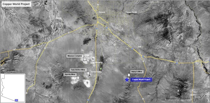
The Project is located within the historic Helvetia Mining District that dates to the 1800's. The deposit lies on the northern end and western foothills of the Santa Rita Mountain range 28 miles (45 km) southeast of Tucson, in Pima County, Arizona (Figure 1-1).
|
The property consists of a combination of fee land, leased land, patented mining claims, unpatented mining claims and mill sites, rights-of-way from the Arizona State Land Department, and grazing leases and permits. The Base Case presented in this Technical Report does not extend beyond the exterior boundary of Copper World's Patented Claims (as defined herein) and private landholdings, whereas the Extension Case contemplates mine activities beyond the exterior boundary and onto Copper World's Unpatented Claims and associated lands.
Precious metals production from the Project is subject to a stream agreement with Wheaton Precious Metals International Ltd. ("Wheaton"). Under the Wheaton stream agreement, Hudbay (BVI) International Inc. ("Hudbay BVI") is entitled to receive an initial deposit of $230M (subject to the satisfaction of certain conditions) against delivery of 92.5% of the gold and silver contained in the mineral products produced from the Project (other than any gold production that is less than 1g/t in concentrate during the first four years of operation), at fixed gold and silver prices of 15% of the market price. In addition, a contingent payment of up to $70M is payable to Hudbay BVI upon completion of the concentrator expansion to 90 kstpd by the fifth anniversary of commercial production, provided that a reduced contingent payment will nonetheless be payable if such expansion is completed by the tenth anniversary of commercial production. Hudbay BVI has entered into a stream agreement with Copper World LLC on substantially the same terms as the Wheaton stream agreement.
In addition, substantially all of the mining properties from which the minerals are contemplated to be extracted in the Base Case and Extension Case are subject to a 3% Net Smelter Returns (NSR) royalty.
Figure 1-1: Project Property Location
|
1.3 Geological Setting & Mineralization
The deposits are within the Laramide belt, a major porphyry province that includes several other world class deposits. Mesozoic subduction and associated magmatism and tectonism in the southwestern United States and northern Mexico generated extensive and relevant porphyry copper mineralization. Compressional tectonism during the Mesozoic and early Cenozoic Laramide Orogeny caused folding and thrusting, accompanied by extensive calc-alkaline magmatism. Tertiary faulting juxtaposed mineralized and unmineralized rocks in large-scale block faulting that produced the present basin and range geomorphology that is typical throughout southern Arizona.
The Project is in the northern block of the Santa Rita Mountains, dominated by Precambrian granite with slices of Paleozoic and Mesozoic sediments, and small stocks and dikes of quartz monzonite or quartz latite porphyry that are related to porphyry copper and skarn mineralization. Tertiary faulting has significantly segmented the original stratigraphy, juxtaposing mineralized and unmineralized rocks. Mineralization occurs as both copper oxides and sulfides in skarns, and intrusive porphyry.
1.4 Deposit Types
Genetically, skarns form part of the suite of deposit styles associated with porphyry copper centers. The skarns were formed as the result of thermal and metasomatic alteration of Paleozoic carbonate and, to a lesser extent, Mesozoic clastic rocks. Near-surface weathering has resulted in the oxidation of the sulfides in the overlying Mesozoic units at the East Deposit, and near-surface Paleozoic units at Copper World.
Mineralization is mostly in the form of primary (hypogene) copper, molybdenum, and silver bearing sulfides, found in stockwork veinlets, and disseminated in the altered host rock at depth. Near the surface, along structural zones, and in quartzite units, oxidized copper mineralization is present. The oxidized mineralization occurs as mixed copper oxide and copper carbonate minerals. Enriched supergene chalcocite rich zones associated with secondary mineralization are found in and beneath the oxidized mineralization.
1.5 Exploration
Prospecting began in the Helvetia-Rosemont Mining District in the mid-1800s, and by 1875, copper production was first recorded, which continued sporadically until 1951. By the late 1950s, exploration drilling had discovered the East Deposit. A succession of major mining companies subsequently conducted exploratory drilling focused on the East Deposit and the nearby Broadtop Butte and Peach-Elgin mineralized areas.
Two infill drilling campaigns were completed by Hudbay around the East Deposit in 2014 and 2015. In addition to chemical assaying, magnetic susceptibility and conductivity measurements were also taken. Hudbay analyzed all samples of the 2014 and 2015 drilling programs with ICP multi-element geochemistry. This new geochemical data set was used to model stratigraphy and geochemical attributes and proved to be a useful tool for geological modeling and vectoring.
In October 2020, Hudbay resumed exploration drilling on targets at its Copper World private land claims located north and west of the East Deposit. The drill program has continued until present, focusing mostly on the Peach, Elgin, West and Broadtop Butte areas, as well as establishing the continuity to the East Deposit through the Bolsa area.
|
1.6 Drilling, Sample Preparation, Analytical Procedures & Data Validation
All available data from both historical and modern drilling was consolidated for inclusion in the geological model for the 2023 PFS (Table 1-1). Drilling activities at site resumed in 2024 with a focus on geotechnical and condemnation drilling. Some limited infill drilling activities were also initiated in 2025, mostly in the West and Broadtop Butte areas as operational readiness activities. No resource model update was undertaken since the 2023 PFS as the recent drilling is very limited and not deemed to have any material impact on the Definitive Feasibility Study mine plan. Out of a total of 1,754 drill holes used for the 2023 resource model, 1,277 holes have intersected copper mineralization and were used to define the mineralized envelopes for the Copper World and East Deposits.
Sample preparation, security, and analytical procedures used by Augusta and Hudbay since 2005 meet current industry accepted standards. QA/QC procedures including the use of certified reference material, blanks and interlaboratory checks on pulp duplicates have resulted in acceptable precision, accuracy, and contamination level. Statistical comparisons and database entry checks of older historical drilling data did not identify any significant biases or database quality issues. Specific gravity was measured in laboratories using water displacement on core and validated with box weight measurements to derive in-situ density estimates for each mineralization domain.
Independent data verification by Hudbay was conducted under the supervision of Olivier Tavchandjian, Hudbay's Senior Vice President, Exploration and Technical Services, and a Qualified Person pursuant to NI 43-101, and it is the opinion of the author that the quality of the data is suitable for use in resource calculations and that sampling to date is representative of the deposit.
Table 1-1: Summary of Drilling Used for the Resource Model
|
|
|
|
Churn |
Rotary |
RC |
DDH |
All DH Types |
||||||||||
|
Company |
Time Period |
Holes |
(m) |
(ft) |
Holes |
(m) |
(ft) |
Holes |
(m) |
(ft) |
Holes |
(m) |
(ft) |
Holes |
(m) |
(ft) |
|
|
Lewishon |
1956 |
1957 |
28 |
3,042 |
9,980 |
- |
- |
- |
- |
- |
- |
18 |
2,249 |
7,377 |
46 |
5,290 |
17,357 |
|
Banner |
1961 |
1963 |
- |
- |
- |
- |
- |
- |
- |
- |
- |
34 |
3,828 |
12,560 |
34 |
3,828 |
12,560 |
|
Anaconda |
1961 |
1972 |
- |
- |
- |
- |
- |
- |
- |
- |
- |
210 |
54,376 |
178,399 |
210 |
54,376 |
178,399 |
|
Anamax |
1970 |
1983 |
- |
- |
- |
29 |
1,821 |
5,974 |
- |
- |
- |
186 |
39,008 |
127,979 |
215 |
40,829 |
133,953 |
|
Asarco |
1988 |
1992 |
- |
- |
- |
1 |
426 |
1,399 |
- |
- |
- |
11 |
4,479 |
14,695 |
12 |
4,905 |
16,094 |
|
Augusta |
2005 |
2012 |
- |
- |
- |
34 |
10,002 |
32,815 |
- |
- |
- |
87 |
40,381 |
132,483 |
121 |
50,383 |
165,298 |
|
Hudbay |
2014 |
2022 |
- |
- |
- |
- |
- |
- |
146 |
21,687 |
71,150 |
970 |
174,072 |
571,103 |
1,116 |
195,759 |
642,253 |
|
Summary |
28 |
3,042 |
9,980 |
64 |
12,249 |
40,188 |
146 |
21,687 |
71,150 |
1,516 |
318,393 |
1,044,596 |
1,754 |
355,371 |
1,165,914 |
||
1.7 Mineral Processing & Metallurgical Testing
The metallurgical flowsheet developed for the Project is technically robust, commercially viable, and features low risk across all evaluated ore zones. Key findings establish that a standard crushing, grinding and flotation flowsheet achieves high copper recoveries, produces clean and marketable concentrates, and defines clear environmental pathways for tailings and water management.
The metallurgical baseline was established upon four major modern testing campaigns completed between 2014 and 2026, which built upon older historical work from 1974 to 2013. Since the 2023 PFS, feasibility-level validation work was conducted by BML, SGS, AMinpro, McLelland Labs, Glencore Technology, and TailPro to further define, quantify, and de-risk the mineralogical and metallurgical relationships across all the deposits included in the mine plan. Testing utilized a comprehensive suite of production period composites and geometallurgical subtype composites. These samples cover all lithogeochemical domains and mining envelopes, ensuring excellent spatial and grade representativity.
|
Ore hardness is well-defined across all deposits through an extensive database consisting of 727 variability samples tested to quantify SAG mill resistance, Ball milling energy requirements as well as SMC, Ball mill and bond impact crusher work index measured from composited samples. The hardness metrics were integrated into the resource block model using Random Forest algorithms from multi-element geochemical data, achieving high predictive R² values for the 727 test results and enabling high confidence in throughput modelling.
An extensive quantitative mineralogical database was established using automated mineralogy (QEMSCAN and TIMA-X on over 1,000 samples), Cation Exchange Capacity (CEC), Fourier Transform Near-Infrared Spectroscopy (FTNIR), and X-ray Diffraction (XRD). The primary mineralogical drivers are copper deportment through primary and secondary sulfides transitioning to copper silicates, carbonates, oxides, goethite and wads, talc and clays composition and the abundance of pyrite. To map these mineralogical drivers across the resource block model, predictive models were developed using Random Forest algorithms. These models utilize multi-element geochemical assays to estimate quantitative mineral concentrations, resolving complex, non-linear geological relationships. The resulting machine learning models demonstrate high correlation coefficients (R²) against measured automated mineralogy.
The current flotation protocol replaces historical simple xanthate schemes with a highly effective Controlled Potential Sulfidization (CPS) approach. Standard primary grind followed by sulfidization will maintain an oxidation-reduction potential target. Extensive test work was also conducted to establish the optimum regrind circuit target for the overall cleaner feed. To prevent overgrinding of clays, a cyclone classification circuit has been added to bypass fine material ahead of the regrind mill.
Locked-cycle tests across all campaigns have confirmed the stability of the circuit operation as well as the ability to produce marketable concentrates and to successfully upgrade precious metals into the final copper concentrate.The copper/molybdenum separation was also validated on combined concentrates.
The Project concentrates are clean and highly marketable. Standard penalty elements (lead, zinc, arsenic, bismuth, and mercury) generally remain below smelter penalty limits, while Fluorine was identified as the primary deleterious element. Mineralogical analysis shows that only 10% to 20% of fluorine-bearing minerals (micas, fluorite, apatite) are physically locked with sulfides or talc; the rest report via physical mechanical entrainment. Controlling entrainment, using low-entrainment flotation technology (Jameson Cells), is key to maintaining concentrate grades and keeping fluorine below penalty limits.
Concentrate leaching using the Albion Process™ was also shown to be highly effective, and while it is not included in the Base Case, it is shown as a future upside opportunity in Section 24 of this Technical Report. Extraction kinetics conducted since 2023 have achieved 97% to 99% copper extraction within 36 to 48 hours at atmospheric pressure and 95°C.
|
1.8 Mineral Resource Estimates
The mineral resource models constructed for the Project have been prepared under the supervision of Mr. Olivier Tavchandjian P. Geo. and a Qualified Person pursuant to a NI 43-101. Mr. Tavchandjian is Hudbay's Senior Vice President, Exploration and Technical Services. The mineral resource estimates have been updated based on the revised economic and technical parameters of the Project presented in this Technical Report. The estimates comply with CIM Definition Standards for Mineral Resources and Mineral Reserves (May 10, 2014). The resource modelling and classification methodology applied by Hudbay for the Project is similar and fully consistent with those used at its operating mines and remains unchanged since the 2023 PFS with the exception of the addition of predictive models for material hardness and flotation recovery based on random forest algorithms developed from multi-element geochemical assay results. The flotation predictive model includes the estimated deportment of copper for 6 types of minerals as well as an estimate of abundance of pyrite, talc and swelling clays to ensure their compliance with the future process plant feed requirements.
Hudbay used three-dimensional models of lithological units and mineralization envelopes constructed in Leapfrog Geo™ software using an 'implicit modelling' approach. A wireframe model of the 0.10% copper (Cu) grade shell was also constructed in Leapfrog Geo™. The selection of this copper grade threshold for modelling was based on visual inspection of the spatial and statistical grade distribution. The grade shell includes mineralization grading less than 0.10% Cu where it was deemed necessary to maintain a smooth and continuous three-dimensional envelope. The different lithological units were grouped into four structural domains which were further divided into mineralized envelopes based on the dominance of oxide or sulfide copper mineralization within the 0.10% Cu grade shell. These domains were verified to be also consistent with the main drivers for grinding flotation performance.
Drill core assay intervals for copper (Cu), molybdenum (Mo), silver (Ag), and gold (Au) as well as for all the geochemical elements used for the predictive models of hardness and flotation performance were composited down hole into a fixed length of 25 ft (7.5 m). Composite intervals with lengths less than 12.5 ft (4 m) were appended to the previous composite. The composite intervals were back-tagged with a copper grade-shell code based on the wireframe models to be used during grade estimation. Visual checks were conducted to ensure back-tagging worked as expected.
Exploratory Data Analysis (EDA), including industry standard statistical analysis and variography was undertaken within each mineralized envelope to help develop a plan for block grade estimation.
The block model consists of non-rotated regular blocks of 50 x 50 x 50 ft (15 x 15 x 15 m) as a reasonable proxy for the anticipated Selective Mining Unit (SMU) during open-pit mining. The proportion of the individual blocks within each envelope was estimated using the wireframes prepared in Leapfrog™. A dry bulk density was assigned based on the volume of the block inside each envelope based on the mean value of in-situ density measured from core box weights and validated with laboratory measurements.
The Cu, Mo, Ag, and Au block grade values as well as those elements used in the geometallurgical model were interpolated using an Ordinary Kriging (OK) estimator with a three-pass estimation approach with each successive pass having greater search distances and less restrictive sample selection requirements. A firm boundary approach within each mineralized envelope was employed for all metals.
|
The block model grade estimates were validated by Hudbay geologists through visual inspection comparing composite grades to block grades, statistical checks, and selectivity checks. During its review, Hudbay identified an opportunity to reduce the inherent smoothing of the kriged model. This correction was implemented separately by mineralized envelope based on grade distribution and by areas with consistent drilling density. In each block, the weighted average grade was calculated using the interpolated grade estimate by envelope properly weighted by the volume and density within each envelope.
A Lerchs-Grossman analysis was performed using the block models constructed by Hudbay. Several economic analyses were developed for nested pit shells. The purpose of this assessment was to evaluate free discounted cash flow, revenue, stripping ratio, development, sustaining capital, and as guidance for internal phases, recoveries by processing route and by deposit. The base-case pit shell retained for resource reporting corresponds to a revenue factor of 1.0 with an assumed copper price of $5/lb to ensure potential for economic extraction of the mineral resource estimates.
Table 1-2 shows the mineral resource estimates inclusive of mineral reserve estimates and tabulated within the resource pit shell at a NSR cut-off value of $6.03/st.
Table 1-2: Mineral Resource Statement (Inclusive of Mineral Reserves)
| Category | Metric Tonnes | Short Tons | Cu | Mo | Ag | Au | |
| (in million) | (in million) | (%) | (ppm) | (ppm) | (ppm) | ||
| INCLUSIVE | Measured | 889.5 | 980.5 | 0.42 | 124 | 4.43 | 0.022 |
| Indicated | 346.5 | 382.0 | 0.35 | 109 | 3.32 | 0.015 | |
| M+I | 1,236.0 | 1,362.5 | 0.40 | 120 | 4.12 | 0.020 | |
| Inferred | 309.3 | 341.0 | 0.30 | 103 | 2.69 | 0.012 |
Notes: 1. CIM Definition Standards (2014) were used for reporting the Mineral Resources. 2. Numbers may not compute exactly due to rounding. 3. The Qualified Person is Olivier Tavchandjian. 4. Mineral Resources are estimated as of 1st August 2026. 5. An NSR cut-off value of $6.03/st. was used to define material as ore. 6. Mineral resource estimates are inclusive of mineral reserves and have been tested using pit optimization software with the following assumptions: metal prices of US$5.00/lb Cu, US$20.00/lb Mo, US$3,600/oz Au, and US$50.00/ oz Ag; operating costs of US$1.61/st, US$5.34/st processed, G&A costs of US$0.69/st processed; metallurgical recovery rates vary according to elemental content, and are based on preliminary metallurgical test work. 7. Mineral resources are not mineral reserves as they do not have demonstrated economic viability.
Table 1-3 summarizes the mineral resource estimates exclusive of the measured and indicated mineral resource estimates that have been converted to mineral reserve estimates in Section 1.9. These mineral resource estimates include resource estimates in all categories located inside a pit shell with revenue factor of 1.0 and outside of the mineral reserve pit as well as mineral resource estimates located within the mineral reserve pit not processed within the mine life of the Definitive Feasibility Study and as such excluded from the mineral reserve estimates but still deemed to have potential for economic extraction with additional infill drilling and/or additional metallurgical test work.
|
Table 1-3: Mineral Resource Statement (Exclusive of Mineral Reserves)
| Category | Metric Tonnes | Short Tons | Cu | Mo | Ag | Au | |
| (in million) | (in million) | (%) | (ppm) | (ppm) | (ppm) | ||
| EXCLUSIVE | Measured | 559.5 | 616.8 | 0.40 | 135 | 3.94 | 0.021 |
| Indicated | 286.1 | 315.4 | 0.33 | 112 | 3.15 | 0.015 | |
| M+I | 845.7 | 932.2 | 0.37 | 127 | 3.68 | 0.019 | |
| Inferred | 309.3 | 341.0 | 0.30 | 103 | 2.69 | 0.012 |
Notes: 1. CIM Definition Standards (2014) were used for reporting the Mineral Resources. 2. Numbers may not compute exactly due to rounding. 3. The Qualified Person is Olivier Tavchandjian. 4. Mineral Resources are estimated as of 1st August 2026. 5. An NSR cut-off value of $6.03/st. was used to define material as ore. 6. Mineral resource estimates are exclusive of mineral reserves and have been tested using pit optimization software with the following assumptions: metal prices of US$5.00/lb Cu, US$20.00/lb Mo, US$3,600/oz Au, and US$50.00/ oz Ag; operating costs of US$1.61/st, US$5.34/st processed, G&A costs of US$0.69/st processed; metallurgical recovery rates vary according to elemental content, and are based on preliminary metallurgical test work. 7. Mineral resources are not mineral reserves as they do not have demonstrated economic viability.
Table 1-4 presents a comparison of the previous mineral resource estimates (inclusive of mineral reserve estimates) presented in the 2023 PFS and the 2026 Definitive Feasibility Study mineral resource estimates. The mineral resource estimates provided in the 2023 PFS have been superseded by those presented in this Technical Report as part of the 2026 Definitive Feasibility Study. Overall, the changes between the 2023 and 2026 mineral resource estimates inclusive of the mineral reserve estimates represent the changes in the technical and economic criteria used to report resources, i.e., use of a NSR cut-off replacing a copper cut-off, updated metal price, use of a new flotation recovery formulation and removal of the leachable mineral resource estimates. The change in copper metal contained in the measured and indicated mineral resource estimates is negligible while the metal content in inferred mineral resource estimates has increased by 5%. The overall reduction in headgrade can be explained by the replacement of high-grade leachable resources at low recoveries by lower grade flotation resources but with an estimated higher processing recovery.
Table 1-4: Comparison of 2023 vs 2026 Mineral Resource Estimates
| Category | 2023 PFS | 2026 FS | Delta | ||||
| Million Tonnes | %Cu | Contained Cu Tonnes | Million Tonnes | %Cu | Contained Cu Tonnes | ||
| Measured + Indicated | 1,205 | 0.42 | 5,061,000 | 1,236 | 0.40 | 4,993,440 | -1% |
| Inferred | 275 | 0.32 | 880,000 | 309 | 0.30 | 927,000 | 5% |
Note: 1. Totals may not add up correctly due to rounding.
In the opinion of the author, the construction of the mineral resource model is consistent with the CIM Estimation of Mineral Resources and Mineral Reserves Best Practice Guidelines. The modelling and grade estimation process used is appropriate for a skarn/porphyry-style copper-molybdenum-silver-gold deposit and the resource model is suitable to support mine planning for a large-scale open pit mine. The assumptions used in 2026 to assess reasonable prospects of eventual economic extraction, including metal prices, mining, processing and G&A cost and metallurgical recoveries, are also all considered reasonable by the author.
Other than the risks identified in this Technical Report, the author is not aware of any other environmental, permitting, legal, title, taxation, socioeconomic, marketing, political, or other relevant factors that could materially affect the mineral resource estimate.
|
1.9 Mineral Reserve Estimate
The Mineral Reserve block model is based on the Mineral Resource model described in Section 14. The Resource block model was re-blocked into a regularized 50'x50'x50' Reserve block model. This block size is considered appropriate for the selective mining unit (SMU) size applicable in the envisioned open pit mining operation. This regularization is deemed to introduce sufficient 'internal dilution' into the Reserve mining model to cover all dilution and ore loss ascribed to the ore feed. No further modifying factors have been applied.
Mineral Resources are converted to Mineral Reserves through the demonstration of positive economics following an engineering assessment involving pit optimization, pit design, equipment selection, scheduling and economic evaluation. As was the case in the 2023 PFS, in the Base Case, the conversion of Measured and Indicated Mineral Resources to Mineral Reserves within the limit of the reserve pit is limited to 390 million tonnes due to tailings storage limitations.
The mineral reserves estimation is based on the Base Case mine plan including only measured and indicated mineral resource estimates. The inferred mineral resource estimates within the mineral reserve pit are reported as waste, as they currently do not meet the economic and mining requirements to be categorized as mineral reserves. It cannot be assumed that all or any part of inferred mineral resources will ever be upgraded to a higher category.
Proven and probable mineral reserve estimates for the Project are summarized in Table 1-5. Proven and probable mineral reserves within the designed final pit of the base case total 390 million tonnes of material, grading 0.47% Cu, 103g/tonne Mo, 5.1 g/tonne Ag, and 0.023 g/tonne Au. The total material excavated from the pit is approximately 990 million tonnes.
The mineral reserves estimate presented in this Technical Report is dependent on market prices for the contained metals, metallurgical recoveries and ore processing, mining, and general/administration cost estimates. Mineral reserve estimates in subsequent evaluations of the Copper World deposits may vary according to changes in these factors. Other than the risks identified in this Technical Report, there are no other known mining, metallurgical, infrastructure or other relevant factors that may materially affect the mineral reserve estimates.
The 2026 mineral reserve estimates present a comparable tonnage at a lower average copper grade than the 2023 PFS mineral reserve estimates which were reported at 385 million tonnes at 0.54% Cu. The reduction in grade relates to a change in mine planning strategy aiming at an approximately 20% smaller pit compared to the 2023 PFS, resulting in a significant reduction in the strip ratio. As the space for tailings and waste rock disposal is the main constraint on mine planning in the Base Case, the significant reduction in the strip ratio offsets the loss in metal production while also considering the impact of a new flotation recovery formulation and updated metal price forecast and cost assumptions. The higher-grade mineralization to be recovered at the expense of more waste excavation is not lost and is later recovered in the mine plan of the Extension Case which is not subject to the same land constraints for waste and tailings disposal.
|
Table 1-5: Proven & Probable Mineral Reserves Total - Final Pits
| Category | Metric Tonnes (in million) |
Short Tons (in million) |
Cu (%) |
Mo (ppm) |
Ag (ppm) |
Au (ppm) |
NSR ($ per ton) |
| Proven | 330.0 | 363.7 | 0.47 | 105 | 5.25 | 0.024 | 32.31 |
| Probable | 60.4 | 66.6 | 0.46 | 94 | 4.14 | 0.018 | 30.46 |
| Total | 390.4 | 430.3 | 0.47 | 103 | 5.80 | 0.023 | 32.03 |
Notes: 1. CIM Definition Standards (2014) were used for reporting the Mineral Reserves. 2. Numbers may not compute exactly due to rounding. 3. The Qualified Person is Olivier Tavchandjian. 4. Mineral Reserves are estimated as of 1st August 2026. 5. An NSR cut-off value of $5.80/st. was used to select material for processing. A minimum Cu grade of 0.1% and a minimum Cu recovery of 48% were also applied due to the limited tailings capacity.
1.10 Mining Methods
The Copper World Project will employ conventional open-pit, truck-and-shovel mining methods across four primary pits: East, Broadtop, West, and Peach-Elgin. The overall mine plan integrates essential supporting infrastructure, including waste rock facilities (WRFs), grade-segregated ore stockpiles, a tailings storage facility (TSF), and IPCC system (refer to Figure 1-2). Mining operations are scheduled to run continuously, 24 hours per day, 365 days per year.
Under the Base Case mine plan, total production encompasses 390 million tonnes of ore and approximately 589 million tonnes of waste, yielding a life-of-mine (LOM) strip ratio of 1.5:1 (waste-to-ore), inclusive of pre-production stripping. The Base Case establishes a 15-year LOM, in addition to a two-year pre-stripping period. Economic material will be delivered to a conventional flotation plant for processing.
Mill throughput is designed to ramp up to 60 kstpd over the initial seven months of Year 1, followed by a planned expansion to 90 kstpd in Year 5. The production schedule prioritizes the extraction and processing of higher-margin material early in the LOM. Lower-grade material is routed to grade-segregated stockpiles and reclaimed opportunistically to optimize mill feed grades and satisfy blending parameters.
A combined pit optimization process was completed for the four deposits to evaluate overarching economic potential and establish an indicative mining sequence that explicitly incorporates spatial constraints. For the Base Case, the ultimate pit limits were selected to maximize resource extraction based on baseline economic assumptions, while remaining strictly confined within the exterior boundary of the currently permitted footprints for mining, WRFs, and the TSF.
Open pit design parameters are predicated on the selected mining equipment, operating strategy, and geotechnical slope stability criteria. To ensure achievable production schedules and constrain pushback sequencing, the vertical advance rate is capped at 10 benches per year. Haul road dimensions are designed to minimize overall strip ratios while maintaining strict safety standards to accommodate both staffed and Autonomous Haulage System (AHS) fleet operations.
The Base Case mining schedule encompasses 13 distinct pushback phases. This sequence targets high-grade, low-strip-ratio mineralization early in the LOM while smoothing the waste-stripping profile to ensure continuous ore exposure.
|
Figure 1-2: Base Case Layout of the Mining Infrastructures
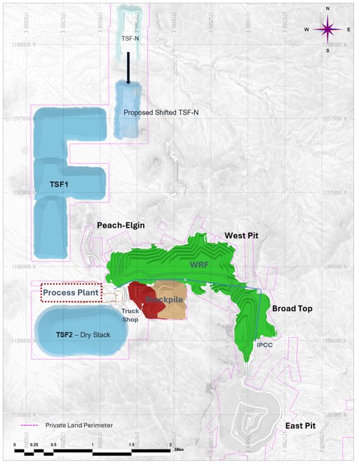
The operation is configured for large-scale mining on 50-foot benches. Primary loading will utilize Caterpillar 6060 hydraulic shovels and 995 front-end loaders. Haulage will be conducted by a fleet of 320-ton AHS Caterpillar 794 trucks operating on dual-lane ramps. Drilling will be executed by Caterpillar MD6310 and Epiroc D65LF rotary blast hole drills, supported by a fleet including Caterpillar D10 track dozers, 24M motor graders, and 777 water carts.
|
To efficiently manage high material tonnages, an IPCC system is integrated into the East Pit. Scheduled to become operational in Year 4, the system will convey ore from the East Pit directly to the processing plant and stockpiles. The IPCC features a 91 kstpd nominal capacity gyratory crusher, permanently located at the southern end of the Broadtop Phase 3 pit. Its implementation is paired with a sequential pit-backfill strategy that facilitates WRF expansion.
Waste rock will be stored in designated WRFs and within the exhausted Peach-Elgin, Broadtop, and West pits. Material will be end-dumped in 100-foot lifts, with crests set back and dozed to target angles for concurrent reclamation. The WRF design provides sufficient storage capacity, including 45 Mt specifically designated for TSF construction.
Due to strict property boundary constraints, 3D block-modeled stockpiles with a nominal capacity of approximately 100 Mt were designed to optimize ore handling and grade segregation. This stockpiling strategy ensures a continuous supply of full-capacity mill feed during high-strip-ratio periods while preserving long-term Mineral Reserves.
The Base Case mine production schedule consists of the following main periods:
• Pre-production period: A two-year phase (Year -2 and Year -1) during which the owner-operated mining fleet will execute pre-stripping activities.
• Steady-Stage and Expansion: Production is maintained at 60 kstpd until the mill is expanded to 90 kstpd in Year 5.
Figure 1-3: Mine Production Over the Base Case Life of Mine Plan
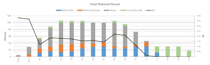
The Extension Case evaluates a brownfield extension featuring a conceptual 37-year LOM (plus two years of pre-stripping). This Extension scenario contemplates the extraction of approximately 1,048 Million tonnes of mill feed and 1,880 Million tonnes of waste. Under this plan, the private land-type constraints of the Base Case are relaxed after Year 10, provided operations remain within the broader boundaries of Hudbay's Unpatented Claims. Four additional mining phases in the East Deposit support this extended LOM.
The Measured and Indicated Mineral Resources incorporated into the Extension Case require the use of federal lands outside the current Project perimeter. The Extension Case is not the selected development option and would require Copper World to apply for and obtain federal permits, including completion of a NEPA process that has not yet been initiated, prior to Year 10.
|
Figure 1-4 displays the mine production and material movement over the Extension Case 37-year life of mine plan (plus two years of pre-stripping.
Figure 1-4: Mine Production Over the Extension Case Life of Mine Plan
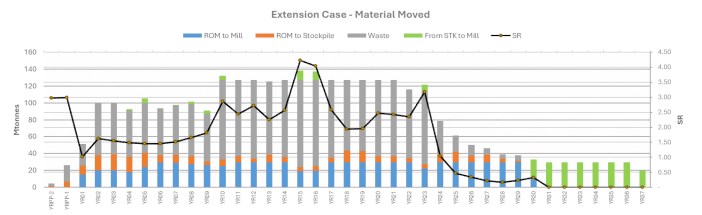
Overburden and other waste rock exposed during mining will be placed into the Waste Rock Facilities (WRF). Upon completion of mining activities in the Peach-Elgin, Broadtop, and West pits, these areas will be utilized for long-term waste rock storage. Waste will be end-dumped in 100 ft high lifts with dump faces at the angle of repose. The WRF crests will be set back to allow simple dozing of the crests down to meet the target re-graded slope angles to support concurrent reclamation. The current Waste Rock Facilities (WRF) design integrates an IPCC in the construction sequence, providing sufficient storage capacity including ~50Mt to be routed to the tailings storage facility.
1.11 Project Infrastructure
The Project infrastructure consists of access and plant roads, a processing complex, electric power supply and distribution, water supply and distribution, an IPCC system, voice and data communication, waste rock and tailings storage facilities, and other ancillary facilities.
Access to the Project area is through South Santa Rita Road, at the point between South Nogales Highway and South Country Club Road on East Sahuarita Road, in the Town of Sahuarita, Pima County, Arizona. The Project's primary access road will intersect Santa Rita Road and give entrance to the in-plant roads, haul roads and other roads used to access the facilities.
The initial development phase centers on a 60 kstpd concentrator plant that processes a mix of primary and secondary copper sulfides with some other copper bearing minerals using conventional crushing, grinding, flotation, molybdenum separation, concentrate dewatering, and tailings thickening. It includes a two-stage cyclone station used to produce sand for TSF dam construction. The concentrator expansion intentionally avoids wholesale replacement or resizing of active operating equipment. Instead, throughput and production increases are achieved via parallelization and modular additions of proven commercial technologies. This design methodology lowers technical execution risk, simplifies constructability, minimizes operational downtime during tie-ins, and offers a clear, staged progression for the Project's lifecycle. An in-pit crushing and conveyance system is also added and operational in Year 4.
|
Tucson Electric Power (TEP) will provide service via a 138 kV transmission line connected at the proposed Toro Switchyard located in Hudbay's private land parcel (Sanrita South). The power system is designed to support the 60 kstpd base case concentrator, the 90 kstpd throughput expansion, the IPCC expansion, and tailings expansions (and also has the capacity to support a concentrate leach facility in the future).
The water supply source identified for the Project is groundwater from the Santa Cruz Basin, which lies west of the Project and the Santa Rita Mountains. Hudbay has a permit to withdraw groundwater for mineral extraction and metallurgical processing in the amount of 6,000 acre-feet per year (which is currently set to expire in January 2028 but is renewable for successive 20-year terms). Fresh water is treated at a dedicated site water treatment facility, supplying offices, change houses, and safety showers. Potable storage accommodates 48 hours of average consumption. Process Water is sourced primarily from tailings thickener overflow and supplemented with site stormwater/process pond run-off. The site water management system separates clean stormwater from contact process water to minimize treatment requirements and protect regional groundwater. Data networking and telecommunication systems will be integrated into a common infrastructure. Mobile radio will also be used by the mine and plant operation personnel for daily control and communications while outside the offices.
The Project includes the construction of three Tailings Storage Facilities in the Base Case scenario: TSF-1, TSF-2, and the southern portion of the area designated as TSF-N. The Extension Case assumes TSF-N is not built and includes two other TSFs in addition to TSF-1 and TSF-2. Tailings management incorporates both conventional (hydraulic) deposition and filtered tailings dry stacking. Foundations were conservatively modeled as alluvial/colluvial soil. Slope stability was evaluated under static (drained/undrained) and pseudo-static loading conditions. All safety factors meet or exceed the design limits specified by the Arizona Department of Environmental Quality (ADEQ) Best Available Demonstrated Control Technology (BADCT) Guidance Manual and are designed in accordance with the CIM TSM tailings standards.
The Waste Rock Facilities (WRF), will receive waste rock from the pits, starting from the west side area. The WRF will be large enough to contain the estimated 589 million tonnes of waste rock generated from within the proposed limits of the pits for the Base Case. In the Extension Case, an additional WRF would be established in close proximity to the East Pit. Stability was evaluated under static and pseudo-static conditions using limit equilibrium methods on critical cross-sections for circular and non-circular slip surfaces. Waste rock is classified as predominantly non-acid generating (NAG), presenting a negligible risk of acid mine drainage.
Other site buildings have been centralized in order to optimize security, administrative communication, and utility distribution. These additional infrastructures include: truck shop, welding shop, tire workshop, mine offices & warehouse, emergency response facility, security & gatehouses, laydown and logistics, fuel storage and change house facilities.
1.12 Marketing
The Project will produce saleable metals in the form of copper and molybdenum concentrates.
Pursuant to the terms of the Joint Venture Agreement, Hudbay is entitled to 70% of the copper and molybdenum concentrate production from the Project and Mitsubishi is entitled to the remaining 30%. Each partner will enter into an offtake agreement with Copper World LLC to purchase its pro rata share of the concentrates on the same, industry standard, terms.
|
Global copper concentrate fundamentals are expected to be strong in the medium/longer term.
Smelters globally are expected to seek significant metal production to attempt to satisfy the expected increase in demand driven by, among other things, the electrification megatrend, in particular to support the rapid expansion of Artificial Intelligence (AI) datacentres. However, smelters' ability to do so may be constrained by a shortage of mine production.
Global markets are expected to compete aggressively for concentrate supply, providing a strong market for sales of the Copper World concentrate.
While copper will be the main product sold, Copper World will also produce molybdenum concentrate as a byproduct. Medium/long term fundamentals for molybdenum are forecast to be constructive. Regionally, the US will continue to import molybdenum concentrate, as it does now from locations such as South America. Consequently, Copper World production is expected to be absorbed regionally, in part helping to satisfy growing molybdenum oxide demand related to the reshoring of the US manufacturing base.
Table 1-6 provides a summary of the commodity price assumptions used in the economic evaluation of the Project.
Table 1-6: Commodity Price Assumption
| Metric | Unit | Long-Term Price |
| Metals | ||
| Copper1 | $/lb | 5.00 |
| Molybdenum1 | $/lb | 17.50 |
| Gold - Offtaker1 | $/oz | 3,600.00 |
| Silver - Offtaker1 | $/oz | 45.00 |
| Gold - Stream (15% of market price)2 | $/oz | 540.00 |
| Silver - Stream (15% of market price)2 | $/oz | 6.75 |
| NSR Royalty | % | 3.00 |
Notes: 1. Commodity price assumptions in the table represent long-term prices starting in Year 3 of operations. Price assumptions in Year 1 and Year 2 of operations are as follows: copper $5.50/lb and $5.13/lb, gold $3,788/oz and $3,638/oz, silver $46.25/oz and $45/oz, molybdenum $17.50/lb in both years. 2. Gold and silver stream based on 15% of the market price as stipulated in the stream agreement with Wheaton, estimated at $540/oz for gold based on $3,600/oz gold price assumption and $6.75/oz silver based on $45/oz silver price assumption.
1.13 Environmental Studies, Permitting, & Social or Community Impact
As part of both current and past project activities, numerous surveys and studies related to the biological and cultural aspects of the site have been completed. Additionally, the geochemical characterization of site materials has been performed along with groundwater and surface water studies.
The Base Case presented in this Technical Report only requires state, county, and local permits. Federal authorizations are required for the Extension Case.
State, county, and local permits have been delivered from the following agencies:
• Arizona Corporation Commission (ACC)
|
• Arizona Department of Environmental Quality (ADEQ)
• Arizona Department of Water Resources (ADWR)
• Arizona State Mine Inspector (ASMI)
• Pima County
• Town of Sahuarita
All the major permits required for the construction and start of operations have been issued and are set out below. Certain permit amendments and renewals will be required in the normal course after the Project commences operations.
• Groundwater Withdrawal Permit (issued by ADWR)
• Arizona Mined Land Reclamation Plan (issued by ASMI)
• Class II Air Quality Control Permit (issued ADEQ)
• Aquifer Protection Permit (APP) (issued ADEQ)
• Certificate of Environmental Compatibility (CEC) (for powerline, issued to TEP by the ACC)
• Floodplain Use Permit (FUP) (for waterline within utility corridor, issued by Pima County)
Permit modifications will be required to incorporate the IPCC, the concentrator expansion to 90 kstpd and the filtered tailings facility.
The Project will include conventional tailings disposal with three tailings storage facilities. The Project will meet the Arizona Department of Environmental Quality (ADEQ) Best Available Demonstrated Control Technology (BADCT) requirements (includes facilities such as the Waste Rock Facility, and Tailings Storage Facilities). Equipment specifications, such as for dust collector efficiency, will be part of permit requirements for an air quality control permit issued by ADEQ. Additionally, monitoring and reporting requirements will be required for most of the permits associated with the Project.
Regarding community outreach and other social commitments, specific allocations will be determined as the Project progresses and the community is further engaged. Additionally, Hudbay is committed to the preservation of historical and cultural resources as well as the protection of endangered and other protected species.
Hudbay actively integrates stakeholder and public feedback from permit comment periods into its ongoing mitigation planning, maintaining a dedicated cost allowance within the Project's financial model. Cultural resources are protected via rigorous pre-disturbance field surveys and site management plans.
The net economic benefit of the Project is estimated at $1,126M for the Base Case, considering only total U.S. taxes over the life of mine, including $200M to the State of Arizona and $362M in local property taxes. It is anticipated to generate over 750 construction jobs, 500 permanent operating roles, and up to 3,000 indirect employment opportunities within Arizona.
|
Hudbay is responsible for reclamation of surface disturbances attributed to the Project. Reclamation and closure of private lands are regulated by ADEQ and ASMI. Closure and reclamation bonding is apportioned amongst the agencies as applicable.
The project is backed by a comprehensive $137.8M closure and reclamation strategy. Financial assurance is fully secured from the initiation of project construction via the surety market. Requisite bonds are maintained at an annual premium fee of 1% of the total notional value. Post-closure maintenance plans commit to a 5-year reclamation success monitoring window alongside tailing drain-down solution management that can extend up to 30 years.
1.14 Capital & Operating Costs
1.14.1 Base Case Capital and Operating Costs
Total life of mine capital costs of $3,463M consist of $2,070M initial growth, $710M expansionary growth, $484M sustaining and $199M capitalized stripping costs. Costs are presented in 2026 dollars, unless stated otherwise, and are reflected net of equipment financing.
Growth capital includes two phases of construction. The first phase consists of the mine, 60 kstpd concentrator process plant, and related infrastructure totalling $2,070M to be incurred during the 12 quarters prior to production in 2029. The second phase consists of optimizations including the molybdenum processing plant, IPCC and concentrator expansion to 90 kstpd. The molybdenum processing plant is planned for Year 1 of operations and totals $25M. The IPCC is operational in Year 4 of operations to optimize hauling and rehandling costs as the mine operations approach the East Pit and totals $242M. The concentrator expansion is completed in Year 4 of operations to expand the daily processing capacity to 90 kstpd starting the following year, incorporating additional equipment and construction and totals $443M.
The technical studies for the concentrator expansion and IPCC have each been done to a pre-feasibility level of engineering. The expansionary growth capital estimates for each of these projects are subject to a higher degree of uncertainty than the initial growth capital for the Base Case, which has been done to a feasibility level of engineering.
Sustaining capital of $484M is primarily mining-related costs of the waste rock facility, tailings facility, major repairs and overhauls and haul roads, as well as sustaining costs related to plant and general administrative facilities. Capitalized stripping of $199M is composed of capitalized mine operating costs for stripping applicable to the portion of the annual strip ratio in excess of the life of mine strip ratio.
The unit operating costs used in this Definitive Feasibility Study are summarized in Table 1-7. Mining cost is presented on a total cost basis over tonnes of material moved and on an operating cost basis excluding capitalized stripping. Processing and Onsite G&A are presented on a per tonne of feed milled basis.
|
Table 1-7: Base Case - Unit Operating Cost Summary
| Metric | Unit | Total |
| Mining | $/tonne material moved | $1.56 |
| Mining (ex. capitalized stripping) | $/tonne material moved | $1.37 |
| Processing | $/tonne processed | $6.34 |
| Onsite G&A | $/tonne processed | $0.80 |
1.14.2 Extension Case Capital and Operating Costs
In the Extension Case, total life of mine capital costs of $4,657M consist of $2,070M initial growth, $1,105M expansionary growth, $878M sustaining and $604M capitalized stripping costs. Costs are presented in 2026 dollars, unless otherwise stated, and are reflected net of equipment financing.
Growth capital costs are comparable to the Base Case, and also include expanded filtered tailings growth capital of $395M starting in Year 10 of operations.
Sustaining capital of $878M is primarily mining-related costs of the waste rock facility, tailings facility, major repairs and overhauls and haul roads, as well as sustaining costs related to plant and general administrative facilities, and reflects the extension of mine life to 37 years. Capitalized stripping of $604M is composed of capitalized mine operating costs for stripping applicable to the portion of the annual strip ratio in excess of the life of mine strip ratio.
The unit operating costs for the Extension Case are summarized in Table 1-8. Mining cost is presented on a total cost basis over tonnes of material moved and on an operating cost basis excluding capitalized stripping. Processing cost and Onsite G&A are presented on a per tonne of feed milled basis.
Table 1-8: Extension Case - Unit Operating Cost Summary
| Metric | Unit | Total |
| Mining | $/tonne material moved | $1.41 |
| Mining (ex. capitalized stripping) | $/tonne material moved | $1.21 |
| Processing | $/tonne processed | $6.40 |
| Onsite G&A | $/tonne processed | $0.73 |
1.15 Economic Analysis
1.15.1 Base Case Economic Analysis
Based on the Cash Flow Model results, the Base Case has an unlevered after-tax NPV8% and NPV10% of $1,241M and $845M respectively, an after-tax IRR of 16.8%, a payback period of 5.4 years (including investment in the molybdenum processing plant in Year 1, in the IPCC in Year 3 and in the concentrator expansion to 90 kstpd in Year 4), and an annual average EBITDA of $566M at a long-term copper price of $5.00/lb of copper.
The average annual copper production is 95,000 tonnes over a 15-year mine life (excluding pre-stripping), at average cash costs and sustaining cash costs of $1.70 and $2.21 per pound of copper, respectively. The higher average annual production in Years 6 to 10 is due to the concentrator expansion. In the Base Case, the annual copper production drops after year 10 due to a declining mill feed grade while it is maintained at comparable levels for a long period in the Extension case. The IPCC and concentrator expansion to 90 kstpd are based on pre-feasibility level engineering, carry a higher degree of uncertainty, and require permit amendments not yet obtained.
|
Key valuation, production, and cost details from the Base Case are summarized in Table 1-9.
Table 1-9: Base Case - Summary of Project Key Valuation Metrics
| BASE CASE - Summary of Key Metrics (at $5.00/lb Cu long-term) | ||||||
| Valuation Metrics (Unlevered)1 | Unit | Base Case | ||||
| Net present value @ 8% | $ millions | $1,241 | ||||
| Internal rate of return | % | 16.8% | ||||
| Payback period | # years | 5.4 | ||||
| Initial & Expansionary Capital | Unit | Base Case | ||||
| Growth Capital - Initial (Year -3 to Year -1) | $ millions | $2,070 | ||||
| Growth Capital - Molybdenum Plant (Year 1) | $ millions | $25 | ||||
| Growth Capital - In-Pit Crushing and Conveying (Year 3) | $ millions | $242 | ||||
| Growth Capital - Concentrator Expansion (Year 4) | $ millions | $443 | ||||
| Operating Metrics | Unit | Year 1-5 | Year 6-10 | Year 11-15 | LOM | |
| Copper production (annual avg.)2 | 000 tonnes | 84 | 120 | 77 | 95 | |
| EBITDA (annual avg.)3 | $ millions | $531 | $791 | $377 | $566 | |
| Sustaining capital (annual avg.) | $ millions | $50 | $35 | $11 | $32 | |
| Cash cost4 | $/lb Cu | $1.80 | $1.55 | $1.85 | $1.70 | |
| Sustaining cash cost4 | $/lb Cu | $2.57 | $1.98 | $2.17 | $2.21 | |
| BASE CASE - Copper Price Sensitivity Analysis | ||||||
| Copper Price | Unit | $4.50/lb | Base Case $5.00/lb |
$5.50/lb | $6.00/lb | $6.50/lb |
| Net present value1 @ 8% | $ millions | $663 | $1,241 | $1,725 | $2,258 | $2,783 |
| Net present value1 @ 10% | $ millions | $345 | $845 | $1,254 | $1,708 | $2,156 |
| Internal rate of return1 | % | 12.9% | 16.8% | 19.5% | 22.5% | 25.2% |
| Payback period | # years | 5.9 | 5.4 | 5.1 | 4.8 | 4.5 |
| EBITDA (annual avg.)2 | $ millions | $471 | $566 | $652 | $742 | $833 |
Notes: 1. Calculated assuming the following long-term commodity prices: copper price of $5.00 per pound ($5.50 per pound in year 1 and $5.13 per pound in year 2), gold stream price of $540 per ounce (15% of market price), silver stream price of $6.75 per ounce (15% of market price), and molybdenum price of $17.50 per pound. Reflects the terms of the amended Wheaton stream agreement, including an upfront deposit of $230 million in the first year of construction in exchange for the delivery of 92.5% of gold and silver contained in the mineral products produced (other than any gold production that is less than 1g/t in concentrate during the first four years of operation), followed by an additional deposit of up to $70 million upon successful completion of the concentrator expansion to 90,000 short tons per day by the fifth anniversary of commercial production (provided that a reduced contingent payment will nonetheless be payable if such expansion is completed by the tenth anniversary of commercial production). 2. Copper production includes copper contained in concentrate sold. Average annual copper production excludes partial year of production in Year 15. 3. EBITDA is a non-GAAP financial performance measure with no standardized definition under IFRS. For further information, please refer to the company's most recent Management's Discussion and Analysis for the three and six months ended June 30, 2026. 4. By-product credits calculated using amortization of deferred revenue for gold and silver stream sales as per the Company's approach in its quarterly financial reporting. Sustaining cash cost includes sustaining capital expenditures and royalties. Cash cost and sustaining cash cost are non-GAAP financial performance measures with no standardized definition under IFRS. For further information, please refer to the Company's most recent Management's Discussion and Analysis for the three and six months ended June 30, 2026.
1.15.2 Extension Case Economic Analysis
Based on the Cash Flow Model results, the Extension Case has an unlevered after-tax NPV8% and NPV10% of $2,510M and $1,685M respectively, an after-tax IRR of 18.8%, a payback period of 5.4 years (including investment in the molybdenum processing plant in Year 1, the IPCC in Year 3, and concentrator expansion to 90 kstpd in Year 4), and an annual average EBITDA of $522M at a long-term copper price of $5.00/lb of copper. Annual EBITDA is higher in the first 20 years, averaging $684M.
|
The average annual copper production is 89,000 tonnes over a 37-year mine life, at average cash costs and sustaining cash costs of $1.94 and $2.38 per pound of copper, respectively. Annual copper production is higher in the first 20 years, averaging 109,000 tonnes.
The Extension Case is based on measured and indicated mineral resources that are not mineral reserves. Mineral resources that are not mineral reserves do not have demonstrated economic viability.
Key valuation, production, and cost details from the Extension Case are summarized in Table 1-10.
Table 1-10: Extension Case - Key Metrics of the Financial Analysis
|
EXTENSION CASE - Summary of Key Metrics (at $5.00/lb Cu long-term) |
|||||||||||||
|
Valuation Metrics (Unlevered)1 |
Unit |
Extension Case |
|||||||||||
|
Net present value @ 8% |
$ millions |
$2,510 |
|||||||||||
|
Internal rate of return |
% |
18.8% |
|||||||||||
|
Payback period2 |
# years |
5.4 |
|||||||||||
|
Initial & Expansionary Capital |
Unit |
Extension Case |
|||||||||||
|
Growth Capital - Initial (Year -3 to Year -1) |
$ millions |
$2,070 |
|||||||||||
|
Growth Capital - Molybdenum Plant (Year 1) |
$ millions |
$25 |
|||||||||||
|
Growth Capital - In-Pit Crushing and Conveying (Year 3) |
$ millions |
$242 |
|||||||||||
|
Growth Capital - Concentrator Expansion (Year 4) |
$ millions |
$443 |
|||||||||||
|
Growth Capital - Filtered Tailings and Starter Dams (Years 10 and 11) |
$ millions |
$395 |
|||||||||||
|
Operating Metrics |
Unit |
Year 1-10 |
Year 11-20 |
Year 21-30 |
Year 31-37 |
Years 1-30 |
LOM |
||||||
|
Copper production (annual avg.)3 |
000 tonnes |
101 |
117 |
88 |
33 |
102 |
89 |
||||||
|
EBITDA (annual avg.)4 |
$ millions |
$634 |
$735 |
$513 |
$73 |
$627 |
$522 |
||||||
|
Sustaining capital (annual avg.) |
$ millions |
$38 |
$24 |
$19 |
$10 |
$27 |
$24 |
||||||
|
Cash cost5 |
$/lb Cu |
$1.79 |
$1.76 |
$1.94 |
$3.51 |
$1.82 |
$1.94 |
||||||
|
Sustaining cash cost5 |
$/lb Cu |
$2.32 |
$2.20 |
$2.31 |
$3.88 |
$2.27 |
$2.38 |
||||||
|
EXTENSION CASE - Copper Price Sensitivity Analysis |
|||||||||||||
|
Copper Price |
Unit |
$4.50/lb |
Ext. Case$5.00/lb |
$5.50/lb |
$6.00/lb |
$6.50/lb |
|||||||
|
Net present value1 @ 8% |
$ millions |
$1,702 |
$2,510 |
$3,225 |
$3,983 |
$4,726 |
|||||||
|
Net present value1 @ 10% |
$ millions |
$1,033 |
$1,685 |
$2,247 |
$2,851 |
$3,440 |
|||||||
|
Internal rate of return1 |
% |
15.5% |
18.8% |
21.2% |
23.9% |
26.3% |
|||||||
|
Payback period |
# years |
5.9 |
5.4 |
5.1 |
4.8 |
4.5 |
|||||||
|
EBITDA (annual avg.)3 |
$ millions |
$433 |
$522 |
$608 |
$695 |
$782 |
|||||||
Notes: 1. Calculated assuming the following long-term commodity prices: copper price of $5.00 per pound ($5.50 per pound in year 1 and $5.13 per pound in year 2), gold stream price of $540 per ounce (15% of market price), silver stream price of $6.75 per ounce (15% of market price), and molybdenum price of $17.50 per pound. Reflects the terms of the amended Wheaton stream agreement, including an upfront deposit of $230 million in the first year of construction in exchange for the delivery of 92.5% of gold and silver contained in the mineral products produced from the Project (other than any gold production that is less than 1g/t in concentrate during the first four years of operation), followed by an additional deposit of up to $70 million upon successful completion of the concentrator expansion to 90,000 short tons per day by the fifth anniversary of commercial production (provided that a reduced contingent payment will nonetheless be payable if such expansion is completed by the tenth anniversary of commercial production). 2. Payback period does not include filtered tailings capital in Years 10 and 11. 3. Copper production includes copper contained in concentrate sold. 4. EBITDA is a non-GAAP financial performance measure with no standardized definition under IFRS. For further information, please refer to the Company's most recent Management's Discussion and Analysis for the three and six months ended June 30, 2026. 5. By-product credits calculated using amortization of deferred revenue for gold and silver stream sales as per the Company's approach in its quarterly financial reporting. Sustaining cash cost includes sustaining capital expenditures and royalties. Cash cost and sustaining cash cost are non-GAAP financial performance measures with no standardized definition under IFRS. For further information, please refer to the Company's most recent Management's Discussion and Analysis for the three and six months ended June 30, 2026.
|
1.16 Conclusions and Recommendations
This Technical Report describes a Base Case mine plan, as well as the operating cost and capital cost estimates and economic analysis supporting the Base Case and the methodology and assumptions used in support of the mineral resource and mineral reserve estimates update. In addition, an Extension Case including the extension of mining activities on Federal land starting in Year 10 is also presented in this report to illustrate the full potential of the project albeit still limited to only including the current measured and indicated mineral resource estimates for the Project.
In the Base Case, the mining sequence considers the exploitation of the pits and their associated infrastructure over a footprint expected to require only state and local permits for 15 years (plus two years of pre-stripping). During this period, all waste, tailings, and low-grade stockpiles are also disposed of within the perimeter of Hudbay's private land properties. An important constraint on the mine production schedule is the limited space for disposing of waste rocks, tailings, and low-grade stockpiles, resulting in a sub-optimum mining sequence from a strict economic standpoint. However, the current mine plan allows the mine to operate in a sustainable manner for 15 years. Securing Federal permits earlier would unlock significant benefits to the project by removing these important constraints on the mining schedule and likely allow more tons and/or better grades to be mined earlier than currently planned. This is illustrated in the Extension Case which has assumed that mining activities could progress onto Federal land in Year 10.
The mill consists of conventional crushing, grinding, flotation, molybdenum separation, concentrate dewatering and tailings dewatering. Comprehensive metallurgical testwork completed across four major campaigns demonstrates that the proposed process flowsheet for the Copper World Project is strong across the evaluated ore domains and variability suites. The Project produces a clean, marketable copper concentrate averaging approximately 24 % Cu over the life of mine, accompanied by payable precious metals credits. A dual-phase tailings management plan-transitioning from conventional hydraulic disposal (cyclone sand embankment raises and slimes thickening) to having a portion of whole tailings pressure filtered for dry stacking- has been validated and defined with robust engineering design criteria.
For more information on the interpretations and conclusions associated with this Definitive Feasibility Study, please refer to Section 25 of this Technical Report.
For more information on the recommendations associated with this Definitive Feasibility Study, please refer to Section 26 of this Technical Report.
|
2 INTRODUCTION AND TERMS OF REFERENCE
2.1 General
Hudbay Minerals Inc. ("Hudbay" or the "company") is a copper-focused mining company with three long-life operations and a world-class pipeline of copper growth projects in tier-one mining-friendly jurisdictions of Canada, Peru, and the United States. Hudbay's mission is to create sustainable and strong returns by leveraging its core strengths in community relations, focused exploration, mine development, and efficient operations.
This Technical Report presents the results of the 2026 Definitive Feasibility Study, the results of two Pre-feasibility Studies supporting future growth investments in both mill and mine production, and the updated mineral reserve and mineral resource estimates of Hudbay's 70%-owned Copper World project (the "Project") in Pima County, Arizona, USA. The Project is currently held by Copper World LLC, an indirect subsidiary of Hudbay, that is 30% held indirectly by Mitsubishi. In January 2026, Hudbay and Mitsubishi entered into a Joint Venture Agreement that governs the parties' rights and obligations in respect of the Copper World joint venture.
The Base Case development option presented in this Technical Report and used to support the mineral reserve estimates contemplates a 15-year mine plan and is limited to the project outer boundary and design that requires only state and local permits.
An Extension Case, based on measured and indicated mineral resource estimates only, is also presented in Sections 21, 22, 24 and 25 of the Technical Report (the "Extension Case"). The Extension Case contemplates an extension of mine activities beyond the current outer boundary and onto Copper World's Unpatented Claims (as defined herein) and the associated federal lands in Year 10 and would require Copper World to apply for and obtain federal permits. The Extension Case is intended to illustrate the full potential of the Project, but is not the selected development option for purposes of this Technical Report.
This 2026 Definitive Feasibility Study demonstrates the economic viability of the proven and probable mineral reserve estimates. The mineral reserve estimates and the mineral resource estimates that retain potential for economic extraction, supersede and replace the mineral resource and mineral reserve estimates reported in the 2023 Technical Report.
2.2 Terms of Reference
This Technical Report conforms with the 2014 CIM Definition Standards and the requirements of NI 43-101.
Notwithstanding that the Technical Report has an effective date of September 30, 2026, the mineral resource and mineral reserve estimates contained in this Technical Report are estimated as of August 1, 2026.
Additional drilling collected since 2023 has focused on collecting geotechnical information to support engineering studies and condemnation drilling, with also some limited infill drilling of the areas as preparation for pre-stripping activities. The cut-off date for drilling assay results used in the 2023 resource model was March 1, 2023, and remains unchanged for the 2026 Definitive Feasibility Study.
|
Additional mineralogical studies and metallurgical test work have been conducted since 2023 on material collected at all the deposits included in the scope of this Definitive Feasibility Study to confirm the operating parameters of the flotation processing flow sheet.
The capital costs, sustaining capital costs, and operating costs have been reviewed and updated to reflect the current plan, and are expressed in 2026 dollars.
All illustrations (including Maps and Figures) that have been included in this Technical Report shall be deemed to be dated as of the effective date of this Technical Report and prepared by Hudbay unless expressly stated otherwise.
2.3 Qualified Person
The Qualified Person responsible for the preparation of this Technical Report is Olivier Tavchandjian, P. Geo., Hudbay's Senior Vice President, Exploration and Technical Services. Mr. Tavchandjian is not independent from Hudbay.
Mr. Tavchandjian made multiple site visits to the property to maintain familiarity with conditions on the property, to observe the geology and mineralization, and to verify the work completed on the Project. Mr. Tavchandjian has also reviewed and conducted sufficient confirmatory work to act as the Qualified Person for the reporting of the mineral resource and mineral reserve estimates for the Project.
2.4 Site Visits & Responsibility
Site visits to the Project have been completed as shown in Table 2-1. Mr. Tavchandjian, while on site, reviewed the site property, project office, and drilled core samples that remain at site, as well as visiting two external laboratories that were used for the drill campaigns since 2020.
Additional senior personnel of Hudbay involved in the preparation of this document are Chris Marion (Senior Manager Metallurgy Services), Steve Cashin (Vice President Mineral Processing and Operational Excellence) Warren Flannery (Vice President and Head, Arizona Business Unit), Kim Hackney (Copper World Project Director), Clarissa Barazza (Project Associate Managing Director), Jon Leblanc (Chief Financial Officer, US Business Unit) and Steve Hayes (Vice President Marketing). Their involvement in this Technical Report is detailed in Table 3-1.
|
Table 2-1: Dates of Recent Project Site Visits
| Qualified Person | Site Visit Dates |
| Olivier Tavchandjian | May 17- 22, 2021 September 7-11, 2021 February 1-4, 2022 March 8-9, 2022 April 11-14, 2022 May 26-31, 2022 October 12-22, 2022 February 25-28, 2025 May 12-16, 2025 July 7-9, 2026 |
2.5 Unit Abbreviations
The units of measure in this Technical Report are a combination of US standard units and metric units. Unit abbreviations used are noted below in Table 2-2.
Table 2-2: Unit Abbreviations
| Abbreviation | Description |
| $ | United States Dollar |
| °C | Degree Celsius |
| °F | Degree Fahrenheit |
| % | Percent |
| asml | Above mean sea level |
| cm | Centimeters |
| ft | Feet |
| ft2 | Square feet |
| G | Gram |
| g/t | Gram per tonne |
| gal | Gallon |
| km | Kilometer |
| kV | Kilovolt |
| kWh | Kilowatt-hour |
| L | Liters |
| lb | Pound |
| m | Meters |
| m2 | Square meter |
| m3 | Cubic meter |
| min | Minute |
| mm | Millimeters |
| Mt | Million (short) tons |
| oz | Troy ounce |
|
| Abbreviation | Description |
| pct | Percent |
| pdl | Practical detection limit |
| ppm | Parts per million |
| t, st, ton | Tons |
| yd3 | Cubic yard |
| µm | microns |
2.6 Name Abbreviations
Abbreviations of company names, chemical terms, and general terms used in this Technical Report are as shown in Table 2-3.
Table 2-3: Name Abbreviations
| Abbreviation | Company Description |
| "404 Permit" | Permit contemplated by Section 404 of the Clean Water Act |
| ACC | Arizona Corporation Commission |
| ADEQ | Arizona Department of Environmental Quality |
| ADWR | Arizona Department of Water Resources |
| AI | Artificial Intelligence |
| APP | Aquifer Protection Permit |
| ASMI | Arizona State Mine Inspector |
| Banner | Banner Mining Company |
| BLM | Bureau of Land Management |
| BML | Base Met Laboratory |
| BQ | BQ Drill Core Size 1.43 Inches Or 36.4mm Diameter |
| Bureau Veritas | Bureau Veritas Commodities Canada Ltd. |
| BWi | Bond Ball Mill Work Index |
| CEC | Certificate Of Environmental Compatibility |
| Chapi | Laboratorio Metalúrgico Chapi |
| CIM | Canadian Institute of Mining, Metallurgy and Petroleum |
| EPCM | Engineering Procurement and Construction Manager |
| FUP | Floodplain Use Permit |
| HQ | HQ Drill Core Size 2.50 Inches or 63.5mm Diameter |
| Hudbay | Collectively, Hudbay Minerals Inc., its subsidiaries & business units |
| IPCC | In-Pit Crushing and Conveying |
| ISO | International Standards Organization |
| KCA | Kappes, Cassiday & Associates |
| MLRP | Arizona Mined Land Reclamation Plan |
| MSRDI | Mountain State R&D International |
| NEPA | National Environmental Policy Act |
| NHPA | National Historic Preservation Act |
| NQ | NQ Drill Core Size 1.875 Inches or 47.6mm Diameter |
| OREAS | Ore Research and Exploration |
| PQ | PQ Drill Core Size 3.3 Inches Or 83mm Diameter |
| SEDAR+ | System for Electronic Document Analysis and Retrieval |
|
| Abbreviation | Company Description |
| SGS | SGS Canada Inc. |
| Skyline | Skyline Assayers & Laboratories |
| TEP | Tucson Electric Power |
| TIA | Tucson International Airport |
| TIMA | TESCAN Integrated Mineral Analyzer |
| TRICO | Trico Electric Cooperative Inc. |
| UCM | United Copper & Moly LLC |
| USACE | United States Army Corps of Engineers |
| USFS | United States Forest Service |
| USFWS | United States Fish and Wildlife Service |
| VoIP | Voice-over Internet Protocol |
| XPS | XPS Consulting & Test work Services |
| Abbreviation | General Description |
| 3D | Three-Dimensional |
| AAS | Atomic Absorption Spectrometry |
| AG | Acid-Generating |
| AV | Average |
| BA | Biological Assessment |
| BADCT | Best Available Demonstrated Control Technology |
| BO | Biological Opinion |
| CBV | Certified Best Value |
| CCD | Countercurrent Decantation |
| CCTV | Closed-Circuit Television |
| CEC | Cation Exchange Capacity |
| CPS | Controlled Potential Sulfidization |
| CRM | Certified Reference Materials |
| DCIP | Induced Polarization/Resistivity |
| DIA | Discharge Impact Area |
| DWT | JK Drop-Weight |
| EBITDA | Earnings Before Interest, Taxes, Depreciation, And Amortization |
| EDA | Exploratory Data Analysis |
| EIS | Environmental Impact Statement |
| EPMA | Electron Probe Micro-analysis |
| FROD | Final Record of Decision |
| GCL | Geosynthetic Clay Liner |
| HMI | Human Machine Interface |
| HPTPs | Historic Properties Treatment Plans |
| ICP | Inductively Coupled Plasma |
| ICP-ES | Inductively Coupled Plasma Emission Spectroscopy |
| ICP-MS | Inductively Coupled Plasma Mass Spectrometry |
| ICP-OES | Inductively Coupled Plasma Optical Emission Spectroscopy |
| LOM | Life Of Mine |
| MPO | Mine Plan of Operations |
| NAG | Non-Acid Generating |
|
| Abbreviation | General Description |
| NIR | Near Infrared Spectroscopy |
| NN | Nearest Neighbour |
| NPV | Net Present Value |
| NSR | Net Smelter Return |
| OK | Ordinary Kriging |
| OSA | Online Sample Analyzer |
| PAG | Potentially Acid Generating |
| PCS | Process Control System |
| PEA | Preliminary Economic Assessment |
| PFS | Pre-Feasibility Study |
| PLS | Pregnant Leach Solution |
| POC | Point Of Compliance |
| QA/QC | Quality Assurance and Quality Control |
| QEMSCAN | Quantitative Evaluation of Minerals by Scanning Electron Microscopy |
| R2 | Coefficient Of Determination |
| RC | Reverse Circulation |
| RE | Absolute Relative Error |
| RMA | Reduced-To-Major-Axis Regression |
| ROD | Record Of Decision |
| ROM | Run Of Mine |
| RQD | Rock Quality Designation / Rock Quality Data |
| SAG | Semi-Autogenous Grinding |
| SD | Standard deviation |
| SG | Specific Gravity |
| SGI | SAG Grindability Index |
| SMU | Selective Mining Unit |
| SPI® | SAG Power Index |
| SX/EW | Solvent Extraction and Electro-Winning |
| TSF | Tailings Storage Facility |
| WRFs | Waste Rock Facilities |
| XRD | X-Ray Diffraction |
|
Symbol |
Chemical Description |
|
Ag |
Silver |
|
As |
Arsenic |
|
Au |
Gold |
|
Bi |
Bismuth |
|
Ca |
Calcium |
|
Cu |
Copper |
|
Cu-Mo |
Copper-Molybdenum |
|
CuCN |
Cyanide Soluble Copper |
|
CuSS |
Acid-Soluble Copper |
|
Fe |
Iron |
|
H2SO4 |
Sulfuric Acid |
|
K |
Potassium |
|
|
Symbol |
Chemical Description |
|
Mg |
Magnesium |
|
Mo |
Molybdenum |
|
Na |
Sodium |
|
NaCN |
Sodium Cyanide |
|
NaHS |
Sodium Hydrosulfide |
|
P |
Phosphorus |
|
Pb |
Lead |
|
Sb |
Antimony |
|
Scu |
Copper in Sulfides |
|
SCu |
Sulfur Copper |
|
Se |
Selenium |
|
Sn |
Tin |
|
T |
Titanium |
|
Tcu |
Total Copper |
|
Te |
Tellurium |
|
Zn |
Zinc |
|
3 RELIANCE ON OTHER EXPERTS
The information, conclusions, opinions, and estimates contained herein are based on:
• Information available to Hudbay at the time of preparation of this Technical Report, and
• Assumptions, conditions, and qualifications as set forth in this Technical Report.
Table 3-1: Reliance on Other Experts
| Section | Description | Responsible Person |
| 1 | Summary | Olivier Tavchandjian |
| 2 | Introduction & Terms of Reference | Olivier Tavchandjian |
| 3 | Reliance on Other Experts | Olivier Tavchandjian |
| 4 | Property Description & Location | Clarissa Barazza |
| 5 | Accessibility, Climate, Local Resources, Infrastructure & Physiography | Clarissa Barazza |
| 6 | History | Olivier Tavchandjian |
| 7 | Geological Setting & Mineralization | Olivier Tavchandjian |
| 8 | Deposit Type | Olivier Tavchandjian |
| 9 | Exploration | Olivier Tavchandjian |
| 10 | Drilling | Olivier Tavchandjian |
| 11 | Sample Preparation Analyses & Security | Olivier Tavchandjian |
| 12 | Data Verification | Olivier Tavchandjian |
| 13 | Mineral Processing & Metallurgical Testing | Chris Marion and Steve Cashin |
| 14 | Mineral Resource Estimates | Olivier Tavchandjian |
| 15 | Mineral Reserve Estimate | Warren Flannery |
| 16 | Mining Methods | Warren Flannery |
| 17 | Recovery Methods | Chris Marion |
| 18 | Project Infrastructure | Kim Hackney |
| 19 | Marketing | Steve Hayes |
| 20 | Environmental Studies, Permitting, & Social or Community Impact | Warren Flannery |
| 21 | Capital & Operating Costs | Kim Hackney and Warren Flannery |
| 22 | Economic Analysis | Jon Leblanc |
| 23 | Adjacent Properties | Olivier Tavchandjian |
| 24 | Other Relevant Data & Information | Olivier Tavchandjian |
| 25 | Interpretation & Conclusions | Olivier Tavchandjian |
| 26 | Recommendations | Olivier Tavchandjian |
| 27 | References | Olivier Tavchandjian |
|
4 PROPERTY DESCRIPTION & LOCATION
4.1 Location
The Project is located within the historical Helvetia Mining District that dates to the 1800's. The deposits lie on the northern end and western foothills of the Santa Rita Mountain range approximately 28 miles (45 km) southeast of Tucson, in Pima County, Arizona, USA. The subject areas include T17S R13E (Section 36); T17S R14E (Sections 17, 21, 24, 29, and 31); T17S R15E (Section 35). T18S R15E (Sections 2, 10, 11, 13-15, 22-27, and 36); and T18S R16E (Sections 1, 14, 15, 19, 21, 23, 27, and 29-32). Finally, the southernmost sections are located in T19S R15E (Sections 1 and 23) and T19S R16E (Sections 16, 17, and 21) all in the Gila & Salt River Meridian, Pima County, Arizona. The Project geographical coordinates are approximately 31º 86'N and 110º 77'W.
Access to the Project is from Santa Rita and Helvetia Roads from the west and Highway 83, over and across Forest Service roads from the east.
Figure 4-1: Project Property Ownership
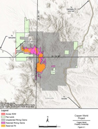
|
4.2 Tenure
The property consists of a combination of fee land, leased land, patented mining claims, unpatented claims, rights-of-way from the Arizona State Land Department, and grazing leases and permits (Figure 4-1).
The core of the Project mineral resource is contained within the 132 patented mining claims that encompass an area of 2,003.46 acres (811 hectares) (the "Patented Claims"). Surrounding the Patented Claims is a contiguous package of 2,099 unpatented and mill-site claims with an aggregate area of more than 22,416 acres (9,072 hectares) (the "Unpatented Claims"). Associated with the Patented Claims and other claims are 81 parcels of land consisting of approximately 5,444.62 acres (2,203 hectares) (the "Associated Lands"). The area covered by the Patented Claims, Unpatented Claims and Associated Lands totals approximately 29,864 acres (12,086 hectares).
The Base Case presented in this Technical Report does not extend beyond the exterior boundary of Copper World's Patented Claims and private landholdings and, as such, the Base Case only requires state and local permits. The Extension Case contemplates extending mine activities beyond the exterior boundary of Copper World's Patented Claims and onto Copper World's Unpatented Claims and the associated federal lands. There are a limited number of small parcels of land that Copper World intends to acquire to consolidate landholdings and optimize the operation.
The federal lands covered by Unpatented Claims are accessible under the provisions of the Mining Law of 1872, subject to approval in accordance with the surface use regulations of the U.S. Forest Service ("USFS") and the Bureau of Land Management ("BLM") and in compliance with the National Environmental Policy Act ("NEPA"). Copper World has not yet applied for these federal approvals.
A table of the legal descriptions, location and acreages of the Patented Claims, Unpatented Claims and Associated Lands is provided Table 4-1, Table 4-2 and Table 4-3.
Table 4-1: Patented Claims - Description and Location
| Tract Number | Locations | Description | PatClaim Name | Acres |
| 305590130 | 24/18S/15E | US PAT MINE HELVETIA DIST A O T 14.20 AC SEC 24-18-15 | A.O.T. | 14.20 |
| 305600090 | 25/18S/15E | US PAT MINE HELVETIA DIST AJAX CON 12.03 AC SEC 25-18-15 | AJAX CONSOLIDATED | 13.98 |
| 305640070 | 29/18S/16E | US PAT MINE HELVETIA DIST AJAX CON M S 5 AC SEC 29-18-16 | AJAX CONSOLIDATED MILLSITE | 5.00 |
| 305590270 | 24/18S/15E | US PAT MINE HELVETIA DIST ALTA COPPER 18.18 AC SEC 24-18-15 | ALTA COPPER | 18.18 |
| 305610050 | 36/18S/15E | US PAT MINE HELVETIA DIST ALTAMONT 20.61 AC SEC 36-18-15 | ALTAMONT | 20.61 |
| 305580120 | 23/18S/15E | US PAT MINE HELVETIA DIST AMERICAN 20.10 AC SEC 23-18-15 | AMERICAN | 20.10 |
| 30558024A | 23/18S/15E | US PAT MINE HELVETIA DIST AMERICAN M S EXC NWLY PTN 4.54 AC SEC 23-18-15 | AMERICAN MILLSITE | 4.54 |
| 30563004B | 24/18S/15E | US PAT MINE HELVETIA DIST AMOLE .459 AC | AMOLE (WESTERLY ORTION) | 0.46 |
| 30563004A | 19/18S/16E | US PAT MINE HELVETIA DIST AMOLE 17.573 AC SEC 19-18-16 | AMOLE (EASTERLY PORTION) | 17.58 |
| 305540110 | 13/18S/15E | US PAT MINE HELVETIA DIST ANTELOPE 17.36 AC SEC 13-18-15 | ANTELOPE | 17.36 |
| 305590060 | 24/18S/15E | US PAT MINE HELVETIA DIST ARCOLA 20.66 AC SEC 24-18-15 | ARCOLA | 20.66 |
|
| Tract Number | Locations | Description | PatClaim Name | Acres |
| 305550110 | 14/18S/15E | US PAT MINE HELVETIA DIST BACK BONE 19.07 AC SEC 14-18-15 | BACK BONE | 19.07 |
| 305590140 | 24/18S/15E | US PAT MINE HELVETIA DIST BALTIMORE 9.62 AC SEC 24-18-15 | BALTIMORE | 9.62 |
| 305540020 | 13/18S/15E | US PAT MINE HELVETIA DIST BLACK BESS 13.54 AC SEC 13-18-15 | BLACK BESS | 13.54 |
| 305550050 | 14/18S/15E | US PAT MINE HELVETIA DIST BLACK HAWK 11.36 AC SEC 14-18-15 | BLACK HAWK | 11.36 |
| 305540090 | 13/18S/15E | US PAT MINE HELVETIA DIST BLACK HORSE 13.81 AC SEC 13-18-15 | BLACK HORSE | 13.81 |
| 30554012A | 13/18S/15E | US PAT MINE HELVETIA DIST BLUE POINT 19.288 AC SEC 13-18-15 | BLUE POINT | 19.28 |
| 305590070 | 24/18S/15E | US PAT MINE HELVETIA DIST BONNIE BLUE 20.66 AC SEC 24-18-15 | BONNIE BLUE | 20.66 |
| 305590280 | 24/18S/15E | US PAT MINE HELVETIA DIST BROADTOP BUTTE 17.15 AC SEC 24-18-15 | BROADTOP BUTTE | 17.15 |
| 305540100 | 13/18S/15E | US PAT MINE HELVETIA DIST BRUNSWICK 18.66 AC SEC 13-18-15 | BRUNSWICK | 18.66 |
| 305550130 | 14/18S/15E | US PAT MINE HELVETIA DIST BUZZARD 20.66 AC SEC 14-18-15 | BUZZARD | 20.66 |
| 305600160 | 25/18S/15E | US PAT MINE HELVETIA DIST CENTRAL 17.86 AC SEC 25-18-15 | CENTRAL | 17.86 |
| 305550040 | 14/18S/15E | US PAT MINE HELVETIA DIST CHANCE 20.16 AC SEC 14-18-15 | CHANCE | 20.16 |
| 305610080 | 36/18S/15E | US PAT MINE HELVETIA DIST CHICAGO 16.66 AC SEC 36-18-15 | CHICAGO | 16.66 |
| 305640020 | 29/18S/16E | US PAT MINE HELVETIA DIST CHICAGO M S 5 AC SEC 29-18-16 | CHICAGO MILLSITE | 5.00 |
| 305610090 | 36/18S/15E | US PAT MINE HELVETIA DIST COCONINO 14.10 AC SEC 36-18-15 | COCONINO | 14.10 |
| 305640030 | 29/18S/16E | US PAT MINE HELVETIA DIST COCONINO M S 5 AC SEC 29-18-16 | COCONINO MILLSITE | 5.00 |
| 305590170 | 24/18S/15E | US PAT MINE HELVETIA DIST COPPER FEND 20.66 AC SEC 24-18-15 | COPPER FEND | 20.66 |
| 305540070 | 13/18S/15E | US PAT MINE HELVETIA DIST COPPER WORLD 20.66 AC SEC 13-18-15 | COPPER WORLD | 20.66 |
| 305600100 | 25/18S/15E | US PAT MINE HELVETIA DIST CUBA 12.03 AC SEC 25-18-15 | CUBA | 12.03 |
| 30563003A | 19/18S/16E | US PAT MINE HELVETIA DIST CUPRITE 20.66 AC SEC 19-18-16 | CUPRITE | 20.66 |
| 305600150 | 25/18S/15E | US PAT MINE HELVETIA DIST CUSHING 15.04 AC SEC 25-18-15 | CUSHING | 15.04 |
| 305580160 | 23/18S/15E | US PAT MINE HELVETIA DIST DAN 2.48 AC SEC 23-18-15 | DAN | 2.48 |
| 305580250 | 23/18S/15E | US PAT MINE HELVETIA DIST DAN M S 2.856 AC SEC 23-18-15 | DAN MILLSITE | 2.85 |
| 30565005A | 30/18S/16E | US PAT MINE HELVETIA DIST DAN WEBSTER 15.19 AC SEC 30 T18S R16E EXC PTN SEC 25-18-15 | DAN WEBSTER | 15.19 |
| 30565005B | 25/18S/15E | US PAT MINE HELVETIA DIST DAN WEBSTER 3.77 AC SEC 25-18-15 EXC PTN SEC 30-18-16 | DAN WEBSTER | 3.77 |
| 30560003B | 30/18S/16E | US PAT MINE HELVETIA DIST DAYLIGHT 5.96 AC SEC 30-18-16 | DAYLIGHT | 5.96 |
| 30560003A | 25/18S/15E | US PAT MINE HELVETIA DIST DAYLIGHT EXC PTN IN SEC 30-18-16 13.21 AC SEC 25-18-15 | DAYLIGHT | 13.21 |
| 305590220 | 24/18S/15E | US PAT MINE HELVETIA DIST ECLIPSE COPPER 20.66 AC SEC 24-18-15 | ECLIPSE COPPER | 20.66 |
| 305600070 | 25/18S/15E | US PAT MINE HELVETIA DIST ELDON 18.984 AC SEC 25-18-15 | ELDON | 18.98 |
|
| Tract Number | Locations | Description | PatClaim Name | Acres |
| 305580180 | 23/18S/15E | US PAT MINE HELVETIA DIST ELGIN 14 AC SEC 23-18-15 | ELGIN | 14.00 |
| 305580220 | 23/18S/15E | US PAT MINE HELVETIA DIST ELGIN M S 4.994 AC SEC 23-18-15 | ELGIN MILLSITE | 4.61 |
| 305610040 | 36/18S/15E | US PAT MINE HELVETIA DIST EMPIRE 10.21 AC SEC 36-18-15 | EMPIRE | 10.21 |
| 305610060 | 36/18S/15E | US PAT MINE HELVETIA DIST ERIE 19.61 AC SEC 36-18-15 | ERIE | 19.61 |
| 305610030 | 36/18S/15E | US PAT MINE HELVETIA DIST EXCELSIOR 20.575 AC SEC 36-18-15 | EXCELSIOR | 20.57 |
| 305540060 | 13/18S/15E | US PAT MINE HELVETIA DIST EXCHANGE 2 6.59 AC SEC 13-18-15 | EXCHANGE NO. 2 | 6.59 |
| 305540050 | 13/18S/15E | US PAT MINE HELVETIA DIST EXCHANGE 20.66 AC SEC 13-18-15 | EXCHANGE | 20.66 |
| 305590090 | 24/18S/15E | US PAT MINE HELVETIA DIST EXILE 16.02 AC SEC 24-18-15 | EXILE | 16.02 |
| 305600110 | 25/18S/15E | US PAT MINE HELVETIA DIST FALLS 16.34 AC SEC 25-18-15 | FALLS | 16.34 |
| 30560012D | 25/18S/15E | US PAT MINE HELVETIA DIST FALLS NO 2 7.32 AC SEC 25-18-15 | FALLS NO. 2 | 7.32 |
| 305540030 | 13/18S/15E | US PAT MINE HELVETIA DIST FLYING DUTCHMAN 20.38 AC SEC 13-18-15 | FLYING DUTCHMAN | 20.38 |
| 305600140 | 25/18S/15E | US PAT MINE HELVETIA DIST FRANKLIN 20.54 AC SEC 25-18-15 | FRANKLIN | 20.54 |
| 30564008A | 29/18S/16E | US PAT MINE HELVETIA DIST FRANKLIN M S 5 AC SEC 29-18-16 | FRANKLIN MILLSITE | 5.00 |
| 305560070 | 15/18S/15E | US PAT MINE HELVETIA DIST GAP 16.25 AC SEC 15-18-15 | GAP | 16.25 |
| 305580170 | 23/18S/15E | US PAT MINE HELVETIA DIST GENERAL 9.17 AC SEC 23-18-15 | GENERAL | 9.17 |
| 305580100 | 23/18S/15E | US PAT MINE HELVETIA DIST GRIZZLY 20.66 AC SEC 23-18-15 | GRIZZLY | 20.66 |
| 305550080 | 14/18S/15E | US PAT MINE HELVETIA DIST HATTIE 12.19 AC SEC 14-18-15 | HATTIE | 12.19 |
| 305550140 | 14/18S/15E | US PAT MINE HELVETIA DIST HEAVY WEIGHT 20.66 AC SEC 14-18-15 | HEAVY WEIGHT | 20.66 |
| 30555012A | 14/18S/15E | US PAT MINE HELVETIA DIST HEAVY WEIGHT M S 5 AC SEC 14-18-15 | HEAVY WEIGHT MILLSITE | 5.00 |
| 305600060 | 25/18S/15E | US PAT MINE HELVETIA DIST HILO CONSOLIDATED 12.19 AC SEC 25-18-15 | HILO CONSOLIDATED | 12.19 |
| 305590120 | 24/18S/15E | US PAT MINE HELVETIA DIST INDIAN CLUB 19.20 AC SEC 24-18-15 | INDIAN CLUB | 19.20 |
| 305590110 | 24/18S/15E | US PAT MINE HELVETIA DIST ISLE ROYAL 20.66 AC SEC 24-18-15 | ISLE ROYAL | 20.66 |
| 305590080 | 24/18S/15E | US PAT MINE HELVETIA DIST KING 20.66 AC SEC 24-18-15 | KING | 20.66 |
| 30565003A | 30/18S/16E | US PAT MINE HELVETIA DIST LA FAYETTE 13.95 AC SEC 30-18-16 | LA FAYETTE | 13.95 |
| 30559025A | 24/18S/15E | US PAT MINE HELVETIA DIST LANDOR 11.200 AC SEC 24-18-15 | LANDOR (WESTERLY PORTION) | 11.17 |
| 30559025B | 19/18S/16E | US PAT MINE HELVETIA DIST LANDOR 4.470 AC SEC 14-18-15 | LANDOR (EASTERLY PORTION) | 4.47 |
| 30561007G | 36/18S/15E | US PAT MINE HELVETIA DIST LAST CHANCE NO 1 15.60 AC SEC 36-18-15 | LAST CHANCE NO. 1 | 15.60 |
| 30561007H | 36/18S/15E | US PAT MINE HELVETIA DIST LAST CHANCE NO 2 18.27 AC SEC 36-18-15 | LAST CHANCE NO. 2 | 18.27 |
| 305590190 | 23/18S/15E | US PAT MINE HELVETIA DIST LEADER 20.66 AC SEC 24-18-15 | LEADER | 20.66 |
| 305550150 | 14/18S/15E | US PAT MINE HELVETIA DIST LIGHT WEIGHT 20.66 AC SEC 14-18-15 | LIGHT WEIGHT | 20.66 |
|
| Tract Number | Locations | Description | PatClaim Name | Acres |
| 305590160 | 24/18S/15E | US PAT MINE HELVETIA DIST LITTLE DAVE 20.66 AC SEC 24-18-15 | LITTLE DAVE | 20.66 |
| 30559029A | 24/18S/15E | US PAT MINE HELVETIA DIST MALACHITE 14.840 AC SEC 24-18-15 | MALACHITE (WESTERLY PORTION) | 14.85 |
| 30559029B | 19/18S/16E | US PAT MINE HELVETIA DIST MALACHITE 6.780 AC SEC 19-18-16 | MALACHITE (EASTERLY PORTION) | 6.79 |
| 305610010 | 36/18S/15E | US PAT MINE HELVETIA DIST MARION 20.66 AC SEC 36-18-15 | MARION | 20.66 |
| 305580140 | 23/18S/15E | US PAT MINE HELVETIA DIST MOHAWK 13.55 AC SEC 23-18-15 | MOHAWK | 13.55 |
| 305660050 | 1/19S/15E | US PAT MINE HELVETIA DIST MOHAWK SILVER 19.76 AC SEC 1-19-15 | MOHAWK SILVER | 19.76 |
| 305560060 | 15/18S/15E | US PAT MINE HELVETIA DIST MONITOR 13.32 AC SEC 15-18-15 | MONITOR | 13.32 |
| 305590240 | 24/18S/15E | US PAT MINE HELVETIA DIST NARRAGANSETT BAY 20.66 AC SEC 24-18-15 | NARRAGANSETT BAY | 20.66 |
| 305580090 | 23/18S/15E | US PAT MINE HELVETIA DIST NEW MEXICO 15.13 AC SEC 23-18-15 | NEW MEXICO | 15.13 |
| 305550010 | 14/18S/15E | US PAT MINE HELVETIA DIST NEWMAN 16.50 AC SEC 14-18-15 | NEWMAN | 16.50 |
| 305600050 | 25/18S/15E | US PAT MINE HELVETIA DIST OLCOTT 5.485 AC SEC 25-18-15 | OLCOTT | 5.48 |
| 305580110 | 23/18S/15E | US PAT MINE HELVETIA DIST OLD DICK 20.13 AC SEC 23-18-15 | OLD DICK | 20.13 |
| 305580270 | 23/18S/15E | US PAT MINE HELVETIA DIST OLD DICK M S 2.196 AC SEC 23-18-15 | OLD DICK MILLSITE | 2.19 |
| 30560012A | 25/18S/15E | US PAT MINE HELVETIA DIST OLD PAP COPPER 20.65AC SEC 25-18-15 | OLD PAP COPPER | 20.65 |
| 305640060 | 29/18S/16E | US PAT MINE HELVETIA DIST OLD PAP M S 5 AC SEC 29-18-16 | OLD PAP MILLSITE | 5.00 |
| 305600130 | 25/18S/15E | US PAT MINE HELVETIA DIST OLD PUT CON 20.65 AC SEC 25-18-15 | OLD PUT CON | 20.65 |
| 305640040 | 29/18S/16E | US PAT MINE HELVETIA DIST OLD PUT M S 5 AC SEC 29-18-16 | OLD PUT MILLSITE | 5.00 |
| 30563002B | 24/18S/15E | US PAT MINE HELVETIA DIST OLUSTEE .450 AC SEC 24-18-15 | OLUSTEE (WESTERLY PORTION) | 0.46 |
| 30563002A | 19/18S/16E | US PAT MINE HELVETIA DIST OLUSTEE 20.36 AC SEC 19-18-16 | OLUSTEE (EASTERLY PORTION) | 20.36 |
| 30559021A | 24/18S/15E | US PAT MINE HELVETIA DIST OMEGA FIRST EXT SOUTH 20.66 AC SEC 24-18-15 | OMEGA FIRST EXTENSION SOUTH | 20.66 |
| 30561007A | 36/18S/15E | US PAT MINE HELVETIA DIST OREGON COPPER 16.08 AC SEC 36-18-15 | OREGON COPPER | 16.08 |
| 305640050 | 29/18S/16E | US PAT MINE HELVETIA DIST OREGON M S 5 AC SEC 29-18-16 | OREGON MILLSITE | 5.00 |
| 305540080 | 13/18S/15E | US PAT MINE HELVETIA DIST OWOSKO 20.66 AC SEC 13-18-15 | OWOSKO | 20.66 |
| 305650040 | 30/18S/16E | US PAT MINE HELVETIA DIST PATRICK HENRY 19.05 AC SEC 30-18-16 | PATRICK HENRY | 19.05 |
| 305560040 | 15/18S/15E | US PAT MINE HELVETIA DIST PEACH 18.07 AC SEC 15-18-15 | PEACH | 18.07 |
| 305590150 | 24/18S/15E | US PAT MINE HELVETIA DIST PILOT 14.70 AC SEC 24-18-15 | PILOT | 14.70 |
| 30560017B | 30/18S/16E | US PAT MINE HELVETIA DIST POTOMAC .5280 AC SEC 30-18-16 | POTOMAC (EASTERLY PORTION) | 0.53 |
| 30560017A | 25/18S/15E | US PAT MINE HELVETIA DIST POTOMAC 19.99 AC SEC 25-18-15 | POTOMAC (WESTERLY PORTION) | 19.99 |
|
| Tract Number | Locations | Description | PatClaim Name | Acres |
| 30558023B | 23/18S/15E | US PAT MINE HELVETIA DIST PTN S CNTL TELEPHONE MS & PTN N2 RECORDER MS & PTN NWLY AMERICAN MS 3.83 AC SEC 23-18-15 | TELEPHONE MILLSITE RECORDER MILLSITE AMERICAN MILLSITE | 3.83 |
| 305650020 | 30/18S/16E | US PAT MINE HELVETIA DIST R G INGERSOLL 20.62 AC SEC 30-18-16 | R. G. INGERSOLL | 20.66 |
| 305600080 | 25/18S/15E | US PAT MINE HELVETIA DIST RAINBOW 7.765 AC SEC 25-18-15 | RAINBOW | 7.76 |
| 305580130 | 23/18S/15E | US PAT MINE HELVETIA DIST RECORDER 6.70 AC SEC 23-18-15 | RECORDER | 6.07 |
| 30558023A | 23/18S/15E | US PAT MINE HELVETIA DIST RECORDER M S EXC NLY PTN 2.64 AC SEC 23-18-15 | RECORDER MILLSITE | 2.64 |
| 30565003J | 30/18S/16E | US PAT MINE HELVETIA DIST SANTA RITA #10 20.56 AC SEC 30 & 31-18-16 | SANTA RITA #10 | 20.56 |
| 30565003K | 31/18S/16E | US PAT MINE HELVETIA DIST SANTA RITA #11 20.56 AC SEC 30 & 31-18-16 | SANTA RITA #11 | 20.56 |
| 30561007F | 36/18S/15E | US PAT MINE HELVETIA DIST SANTA RITA #12 19.62 AC SEC 36-18-15 | SANTA RITA #12 | 19.62 |
| 30560012J | 36/18S/15E | US PAT MINE HELVETIA DIST SANTA RITA #13 10.52 AC SEC 25-18-15 | SANTA RITA #13 | 10.51 |
| 30562034F | 31/18S/16E | US PAT MINE HELVETIA DIST SANTA RITA #13 7.51 AC SEC 31-18-16 | SANTA RITA #13 | 7.51 |
| 30561007E | 36/18S/15E | US PAT MINE HELVETIA DIST SANTA RITA #14 19.16 AC SEC 36-18-15 | SANTA RITA #14 | 19.16 |
| 30561007D | 36/18S/15E | US PAT MINE HELVETIA DIST SANTA RITA #15 13.59 AC SEC 36-18-15 | SANTA RITA #15 | 13.59 |
| 30562034D | 31/18S/16E | US PAT MINE HELVETIA DIST SANTA RITA #15 6.44 AC SEC 31-18-16 | SANTA RITA #15 | 6.44 |
| 30562034C | 31/18S/16E | US PAT MINE HELVETIA DIST SANTA RITA #16 18.92 AC SEC 31-18-16 | SANTA RITA #16 | 18.92 |
| 30561007J | 36/18S/15E | US PAT MINE HELVETIA DIST SANTA RITA #26 20.03 AC SEC 36-18-15 | SANTA RITA #26 | 20.03 |
| 30561007K | 36/18S/15E | US PAT MINE HELVETIA DIST SANTA RITA #27 18.76 AC SEC 36-18-15 | SANTA RITA #27 | 18.76 |
| 30561007L | 36/18S/15E | US PAT MINE HELVETIA DIST SANTA RITA #28 18.57 AC SEC 36-18-15 | SANTA RITA #28 | 18.57 |
| 30562034E | 31/18S/16E | US PAT MINE HELVETIA DIST SANTA RITA #28 2.01 AC SEC 31-18-16 | SANTA RITA #28 | 2.01 |
| 30565003D | 30/18S/16E | US PAT MINE HELVETIA DIST SANTA RITA #4 19 AC SEC 30-18-16 | SANTA RITA #4 | 18.97 |
| 30565003E | 30/18S/16E | US PAT MINE HELVETIA DIST SANTA RITA #5 19.02 AC SEC 30-18-16 | SANTA RITA #5 | 19.02 |
| 30565003F | 30/18S/16E | US PAT MINE HELVETIA DIST SANTA RITA #6 18.99 AC SEC 30-18-16 | SANTA RITA #6 | 18.99 |
| 30565003L | 25/18S/15E | US PAT MINE HELVETIA DIST SANTA RITA #8A 10.75 AC SEC 25-18-15 (S/B 30-18-16) EXC PTN IN SEC 25-18-15) | SANTA RITA #8A | 10.75 |
| 30565003G | 30/18S/16E | US PAT MINE HELVETIA DIST SANTA RITA #8A 3.66 AC SEC 25-18-15 | SANTA RITA #8A | 3.66 |
|
| Tract Number | Locations | Description | PatClaim Name | Acres |
| 30565003M | 36/18S/15E | US PAT MINE HELVETIA DIST SANTA RITA #9 1.02 AC SEC 25-18-15 | SANTA RITA #9 | 1.02 |
| 30565003H | 30/18S/16E | US PAT MINE HELVETIA DIST SANTA RITA #9 SEC 31 & 30-18-16 EXC PTN IN SEC 25-18-15 19.58 AC | SANTA RITA #9 | 19.58 |
| 30560012H | 25/18S/15E | US PAT MINE HELVETIA DIST SANTA RITA FRACTION .98 AC SEC 25-18-15 | SANTA RITA FRACTION | 0.98 |
| 305590230 | 24/18S/15E | US PAT MINE HELVETIA DIST SCHWAB 12.43 AC SEC 24-18-15 | SCHWAB | 12.43 |
| 305550090 | 14/18S/15E | US PAT MINE HELVETIA DIST SILVER SPUR 8.61 AC SEC 14-18-15 | SILVER SPUR | 8.61 |
| 305550100 | 14/18S/15E | US PAT MINE HELVETIA DIST SLIDE 12.88 AC SEC 14-18-15 | SLIDE | 12.88 |
| 305560050 | 15/18S/15E | US PAT MINE HELVETIA DIST SOUTH END 17.81 AC SEC 15-18-15 | SOUTH END | 17.81 |
| 305580190 | 23/18S/15E | US PAT MINE HELVETIA DIST SUNSETE .667 AC SEC 23-18-15 | SUNSETE | 0.67 |
| 305590180 | 24/18S/15E | US PAT MINE HELVETIA DIST TALLY HO 20.38 AC SEC 24-18-15 | TALLY HO | 20.38 |
| 305550060 | 14/18S/15E | US PAT MINE HELVETIA DIST TELEMETER 8.15 AC SEC 14-18-15 | TELEMETER | 8.15 |
| 305580200 | 23/18S/15E | US PAT MINE HELVETIA DIST TELEPHONE 18.66 AC SEC 23-18-15 | TELEPHONE | 18.66 |
| 30558021A | 23/18S/15E | US PAT MINE HELVETIA DIST TELEPHONE M S EXC SLY PTN 4.61 AC SEC 23-18-15 | TELEPHONE MILLSITE | 4.61 |
| 305660060 | 1/19S/15E | US PAT MINE HELVETIA DIST TREMONT 12.86 AC SEC 1-19-15 | TREMONT | 12.86 |
| 305590100 | 24/18S/15E | US PAT MINE HELVETIA DIST VULTURE 15.73 AC SEC 24-18-15 | VULTURE | 15.73 |
| 30559026A | 24/18S/15E | US PAT MINE HELVETIA DIST WARD 16.664 AC SEC 24-18-15 | WARD (WESTERLY PORTION) | 16.67 |
| 305580080 | 23/18S/15E | US PAT MINE HELVETIA DIST WATER WISH 20.66 AC SEC 23-18-15 | WATER WISH | 20.66 |
| 305580150 | 23/18S/15E | US PAT MINE HELVETIA DIST WEDGE 19.31 AC SEC 23-18-15 | WEDGE | 19.31 |
| 30560012G | 25/18S/15E | US PAT MINE HELVETIA DIST WEDGE 6.60 AC SEC 25-18-15 | WEDGE | 6.60 |
| 305580260 | 23/18S/15E | US PAT MINE HELVETIA DIST WEDGE M S 4.987 AC SEC 23-18-15 | WEDGE MILLSITE | 4.98 |
| 30560012F | 25/18S/15E | US PAT MINE HELVETIA DIST WEDGE NO 2 1.28 AC SEC 25-18-15 | WEDGE NO. 2 | 1.28 |
| 305550070 | 14/18S/15E | US PAT MINE HELVETIA DIST WEST END 19.53 AC SEC 14-18-15 | WEST END | 19.53 |
| 305540040 | 13/18S/15E | US PAT MINE HELVETIA DIST WISCONSIN 20.66 AC SEC 13-18-15 | WISCONSIN | 20.66 |
| 305600040 | 25/18S/15E | US PAT MINE HELVETIA DIST YORK 13.38 AC SEC 25-18-15 | YORK | 13.38 |
| 30559026B | 19/18S/16E | US PAT MINE HELVETIA DISTRICT WARD .9240 AC SEC 19-18-16 | WARD (EASTERLY PORTION) | 0.95 |
| 305590200 | 24/18S/15E | US PAT MINE HELVETTA DIST OMEGA 20.66 AC SEC 24-18-15 | OMEGA | 20.66 |
|
Table 4-2: Unpatented Mining Claims - Description and Location
| Name of Claim | Pima County Recorder – Book & Page No./Sequence No. |
BLM AZ State Office Serial No. |
|
| York Fraction Amended |
2022 5436 |
340 804 |
*AMC2198 |
| Travis #1 2nd Amended |
1983 5436 |
253 806 |
*AMC2199 |
| Jim Amended |
995 5436 |
391 802 |
*AMC2200 |
| Isle Royal Fraction Amended |
2054 5436 |
188 808 |
*AMC2201 |
| Indian Club Fraction Amended |
2054 5436 |
187 809 |
*AMC2202 |
| Pilot Fraction Amended |
2051 5436 |
261 810 |
*AMC2203 |
| A.O.T. Fraction Amended |
2054 5436 |
186 811 |
*AMC2204 |
| Walthum Amended |
942 5436 |
87 812 |
AMC2205 |
| Flat Top Amended |
913 5436 |
600 813 |
AMC2206 |
| Round Top Amended |
914 5436 |
1 814 |
AMC2207 |
| Axe Amended |
287 5436 |
258 815 |
AMC2208 |
| Suzy Amended |
934 5436 |
536 816 |
AMC2209 |
| Alachua Amended |
916 5436 |
549 817 |
AMC2210 |
| Malachite Fraction Amended |
2110 5436 |
263 807 |
*AMC2211 |
| MAX 121 B/Relocation | 5609 | 574 | *AMC13284 |
| MAX 123 B/Relocation | 5609 | 576 | *AMC13286 |
| MAX 125 B thru MAX 128 B /Relocation | 5609 | 578-581 | *AMC13288-AMC13291 |
| MAX 129 B/RelocationAmended | 5609 6126 |
582 1202 |
*AMC13292 |
| MAX 130 B thru MAX 149 B/Relocation | 5609 | 583-602 | *AMC13293-AMC13312 |
| MAX 150 B/Relocation Amended |
5609 7073 |
603 604-605 |
*AMC13313 |
| MAX 151 B/Relocation | 5609 | 604 | *AMC13314 |
| MAX 152 B/Relocation Amended |
5609 7073 |
605 606-607 |
*AMC13315 |
| MAX 153 B/Relocation | 5609 | 606 | *AMC13316 |
| MAX 154 B/Relocation Amended | 5609 7073 |
607 608-609 |
*AMC13317 |
| MAX 155 B/Relocation | 5609 | 608 | *AMC13318 |
| MAX 156 B/Relocation Amended | 5609 7073 |
609 610-611 |
*AMC13319 |
| Name of Claim | Pima County Recorder – Book & Page No./Sequence No. |
BLM AZ State Office Serial No. |
|
| Rosaland Amended |
314 1062 |
120 539 |
*AMC14972 |
| Michael M Amended |
314 6062 |
117 540 |
*AMC14973 |
| Lydia J Amended |
314 1062 |
119 541 |
*AMC14974 |
| Ida D Amended |
314 1062 |
118 542 |
*AMC14975 |
| D & D #1 Amended |
759 1062 |
202 543 |
*AMC14976 |
| D & D II Amended |
759 1062 |
201 544 |
*AMC14977 |
| Frijole Amended |
300 1062 |
277 545 |
*AMC14978 |
| Frijole II thru Frijole V | 1062 | 546-549 | *AMC14979-AMC14982 |
| Frijole VII through Frijole IX | 1062 | 551-553 | *AMC14984-AMC14986 |
| Frijole X | 1070 | 494 | *AMC14987 |
| Frijole XI | 1454 | 349 | *AMC14988 |
| Frijole XI Extension | 1454 | 350 | *AMC14989 |
| Deering Springs No. 2 A/Relocation | 5636 | 741 | *AMC15002 |
| Deering Springs No. 4 A/Relocation | 5636 | 742 | *AMC15003 |
| Deering Springs No. 6 A/Relocation | 5636 | 743 | *AMC15004 |
| Deering Springs No. 8 A/Relocation | 5636 | 744 | *AMC15005 |
| Deering Springs No. 10 A/Relocation | 5636 | 745 | *AMC15006 |
| Deering Springs No. 12 A/Relocation | 5636 | 746 | *AMC15007 |
| Deering Springs No. 14 A thru Deering Springs No. 16 A /Relocation | 5636 | 747-749 | *AMC15008-AMC15010 |
| Deering Springs No. 17 A/Relocation Amended | 5636 6126 |
750 1204-1205 |
*AMC15011 |
|
| Name of Claim | PPima County Recorder – Book & Page No./Sequence No.. |
BLM AZ State Office Serial No. |
|
| Deering Springs No. 21 A thru Deering Springs No. 27 A /Relocation | 5636 | 751-757 | *AMC15012-AMC15018 |
| Deering Springs No. 28 A/Relocation Amended |
5636 6126 |
758 1206-1207 |
*AMC15019 |
| Deering Springs No. 29 A thru Deering Springs No. 39 A /Relocation | 5636 | 759-769 | *AMC15020-AMC15030 |
| Deering Springs No. 42 A/Relocation | 5636 | 770 | *AMC15031 |
| Deering Springs No. 51 A/Relocation | 5636 | 771 | *AMC15032 |
| Deering Springs No. 52 A/Relocation | 5636 | 772 | *AMC15033 |
| Kid 1 thru Kid 28 | 3368 | 529-556 | *AMC25210-AMC25237 |
| Kid 29 Amended |
3368 6216 |
557 1001 |
*AMC25238 |
| Kid 34 thru Kid 45 | 3368 | 562-573 | *AMC25243-AMC25254 |
| Kid 46 Amended |
3368 6216 |
574 1003 |
*AMC25255 |
| Kid 47 Amended |
3368 6216 |
575 1005 |
*AMC25256 |
| Wasp 52 Amended |
3786 6216 |
52 955 |
*AMC25257 |
| Wasp 53 Amended |
3786 6216 |
53 957 |
*AMC25258 |
| Wasp 54 thru Wasp 57 | 3786 | 54-57 | *AMC25259-AMC25262 |
| Wasp 58 Amended |
3786 3842 |
58 133 |
*AMC25263 |
| Wasp 60 Amended |
3786 6216 |
59 959 |
*AMC25264 |
| Wasp 61 Amended |
3786 6216 |
60 961 |
*AMC25265 |
| Wasp 101 thru Wasp 107 | 3786 | 63-69 | *AMC25268-AMC25274 |
| Wasp 111 thru Wasp 130 | 3786 | 70-89 | *AMC25275-AMC25294 |
| Wasp 201 thru Wasp 218 | 3786 | 90-107 | *AMC25295-AMC25312 |
| Wasp 313 | 3786 | 144 | *AMC25349 |
| Wasp 315 | 3786 | 146 | *AMC25351 |
| Wasp 317 | 3786 | 148 | *AMC25353 |
| Name of Claim | Pima County Recorder – Book & Page No./Sequence No.. |
BLM AZ State Office Serial No. |
|
| Wasp 319 Amended |
3786 6216 |
150 975 |
*AMC25355 |
| Wasp 321 Amended |
3786 6216 |
152 977 |
*AMC25357 |
| Wasp 323 Amended |
3786 6216 |
154 979 |
*AMC25359 |
| Wasp 325 Amended |
3786 6216 |
156 981 |
*AMC25361 |
| Wasp 327 Amended |
3786 6216 |
158 983 |
*AMC25363 |
| Wasp 329 Amended |
3786 6216 |
160 985 |
*AMC25365 |
| Wasp 331 Amended |
3786 6216 |
162 987 |
*AMC25367 |
| Wasp 333 Amended |
3786 6216 |
164 989 |
*AMC25369 |
| Wasp 335 Amended |
3786 6216 |
166 991 |
*AMC25371 |
| Wasp 337 Amended |
3786 6216 |
168 993 |
*AMC25373 |
| Wasp 339 Amended |
3786 6216 |
170 995 |
*AMC25375 |
| Wasp 341 | 3786 | 172 | *AMC25377 |
| Wasp 343 thru Wasp 354 | 3786 | 174-185 | *AMC25379-AMC25390 |
| Max 41 | 4792 | 584 | *AMC25662 |
| Max 43 | 4792 | 586 | *AMC25664 |
| Max 45 | 4792 | 588 | *AMC25666 |
| Max 47 | 4792 | 590 | *AMC25668 |
| Max 49 | 4792 | 592 | *AMC25670 |
| Max 71 thru Max 120 | 4792 | 614-663 | *AMC25692-AMC25741 |
| Elk 1 thru Elk 6 | 3368 | 576-581 | *AMC27423-AMC27428 |
| Elk 35 Amended |
3368 6121 |
610 1273 |
*AMC27451 |
| Elk 36 thru Elk 37 | 3368 | 611-612 | *AMC27452-AMC27453 |
| Elk 39 | 3368 | 614 | *AMC27455 |
| Elk 41 | 3368 | 616 | *AMC27457 |
| Elk 43 | 3368 | 618 | *AMC27459 |
| Elk 45 | 3368 | 620 | *AMC27461 |
| Elk 70 thru Elk 87 | 3368 | 645-662 | *AMC27465-AMC27482 |
| Alpine #5 Amended |
2221 6121 |
495 183-1284 |
*AMC27513 |
|
| Name of Claim | Pima County Recorder – Book & Page No./Sequence No. |
BLM AZ State Office Serial No. |
|
| Alpine #6 Amended |
2221 6121 |
496 1285-1286 |
*AMC27514 |
| Alpine #7 Amended |
2221 6121 |
497 1287-1288 |
*AMC27515 |
| Alpine #8 Amended |
2221 6121 |
498 1289-1290 |
*AMC27516 |
| Alpine #9 Amended |
2221 6121 |
499 1291-1292 |
*AMC27517 |
| Alpine #10 Amended |
2221 6121 |
500 1293-1294 |
*AMC27518 |
| Alpine #11 Amended |
2221 6121 |
501 1295-1296 |
*AMC27519 |
| Alpine #12 Amended |
2221 6121 |
502 1297-1298 |
*AMC27520 |
| Alpine #13 thru Alpine #18 | 2221 | 503-508 | *AMC27521-AMC27526 |
| Alpine #19 thru Alpine #24 | 2230 | 138-143 | *AMC27527-AMC27532 |
| Santa Rita Wedge | 5901 | 1379 | *AMC28871 |
| Buzzard No. 5 | 2089 | 294 | *AMC36021 |
| SHADOW #1 | 2827 | 63 | *AMC36022 |
| Shadow #4 | 2827 | 66 | *AMC36025 |
| John 1 | 3934 | 508 | *AMC36026 |
| John 2 | 3934 | 509 | *AMC36027 |
| Flying Dutchman No. 2 thru No. 5 | 2089 | 295-298 | *AMC36028-AMC36031 |
| Flying Dutchman No. 6 Amendment |
2089 6121 |
299 1267-1268 |
*AMC36032 |
| Black Bess No. 2 | 2089 | 290 | *AMC36034 |
| K.W.L. | 2078 | 442 | *AMC36036 |
| G.E.J. | 2078 | 443 | *AMC36037 |
| R.F.E. | 2078 | 444 | *AMC36038 |
| R.C.M. | 2078 | 445 | *AMC36039 |
| Sycamore #1 thru Sycamore #3 | 2078 | 446-448 | *AMC36040-AMC36042 |
| Sycamore #4 Amended |
2078 6121 |
449 1299-1300 |
*AMC36043 |
| Name of Claim | Pima County Recorder – Book & Page No./Sequence No. |
BLM AZ State Office Serial No. |
|
| Sycamore #5 Amended |
2078 6121 |
450 1301-1302 |
*AMC36044 |
| Sycamore #6 Amended |
2078 6121 |
451 1302-1304 |
*AMC36045 |
| Sycamore #7 Amended |
2078 6121 |
452 1305-1306 |
*AMC36046 |
| Sycamore #8 Amended |
2078 6121 |
453 1307-1308 |
*AMC36047 |
| Sycamore #9 thru Sycamore #12 | 2078 | 454-457 | *AMC36048-AMC36051 |
| Narragansett Extension #1 | 937 | 372 | *AMC36052 |
| Narragansett Ext. #2 | 937 | 373 | *AMC36053 |
| Narragansett Extension #3 thru #8 | 937 | 374-379 | *AMC36054-AMC36059 |
| Narragansett Ext. No. 9 | 2020 | 358 | *AMC36060 |
| Schwab Extension #1 North West | 1271 | 92 | *AMC36061 |
| Rocky 1 | 3726 | 117 | *AMC36062 |
| Amole No. 2 | 2051 | 262 | *AMC36063 |
| Falls No. 3 thru Falls No. 4 | 2110 | 267-268 | *AMC36065-AMC36066 |
| Perry No. 1 | 2112 | 11 | *AMC36067 |
| Perry #2 thru Perry #12 | 2112 | 12-22 | *AMC36068-AMC36078 |
| Perry #15 Amended |
2112 2139 |
25 441 |
*AMC36081 |
| Perry #16 thru Perry #17 | 2112 | 26-27 | *AMC36082-AMC36083 |
| Perry #18 Amended |
2112 2139 |
28 442 |
*AMC36084 |
| Gunsite 1-A | 1980 | 353 | *AMC36086 |
| Gunsite No. 2 Amended |
1941 1980 |
339 354 |
*AMC36087 |
| Gunsite No. 3 thru Gunsite No. 4 | 1941 | 340-341 | *AMC36088-AMC36089 |
| Gunsite 5A | 2022 | 341 | *AMC36090 |
| Gunsite 6-B | 2110 | 264 | *AMC36091 |
| Gunsite No. 7 | 1941 | 344 | *AMC36092 |
| Gunsite 7A | 2411 | 174 | *AMC36093 |
| Gunsite No. 8 thru Gunsite No. 22 | 1941 | 345-359 | *AMC36094-AMC36108 |
|
| Name of Claim | Pima County Recorder – Book & Page No./Sequence No. |
BLM AZ State Office Serial No. |
|
| Gunsight No. 23 Amended |
1967 2022 |
324 343 |
*AMC36109 |
| Gunsite No. 24 Amended |
1943 1980 |
14 355 |
*AMC36110 |
| Gunsite No. 25 thru Gunsite No. 26 | 1943 | 15-16 | *AMC36111-AMC36112 |
| Gunsite No. 27 | 1943 | 13 | *AMC36113 |
| Gunsight No. 28 – Gunsight No. 43 | 1967 | 325-340 | *AMC36114-AMC36129 |
| Gunsight 44 Amended |
1994 6420 |
152 1007-1008 |
*AMC36130 |
| Gunsight #45 Amended |
1994 6420 |
153 1009-1010 |
*AMC36131 |
| Gunsight #46 thru Gunsight #49 | 1994 | 154-157 | *AMC36132-AMC36135 |
| Gunsight #50 Amended |
1994 2078 |
158 464 |
*AMC36136 |
| Williams Folly | 5406 | 878 | *AMC36137 |
| Williams Folly #2 | 5406 | 879 | *AMC36138 |
| Santa Rita #1 thru Santa Rita #3 | 2148 | 520-522 | *AMC46740-AMC46742 |
| Santa Rita #7 | 2148 | 526 | *AMC46746 |
| Santa Rita #17 thru Santa Rita #25 | 2148 | 536-544 | *AMC46756-AMC46764 |
| Santa Rita #29 thru Santa Rita #31 | 2148 | 548-550 | *AMC46768-AMC46770 |
| Catalina #1 | 2148 | 518 | *AMC46771 |
| Catalina #2 | 2148 | 517 | *AMC46772 |
| Catalina #3 | 2148 | 516 | *AMC46773 |
| Catalina #4 | 2148 | 515 | *AMC46774 |
| Catalina #5A | 2170 | 437 | *AMC46775 |
| Catalina #6A | 2170 | 435 | *AMC46776 |
| Catalina #7 | 2148 | 512 | *AMC46777 |
| Catalina #8 | 2148 | 511 | *AMC46778 |
| Fred Bennett | 936 | 425 | *AMC46779 |
| Fred Bennett Amended |
712 2110 |
107 262 |
*AMC46780 |
| Rosemont #9 Amended |
936 2078 |
424 466 |
*AMC46781 |
| Rosemont #11 | 936 | 420 | *AMC46782 |
| Rosemont 11-A | 2078 | 458 | *AMC46783 |
| Name of Claim | Pima County Recorder – Book & Page No./Sequence No. |
BLM AZ State Office Serial No. |
|
| Rosemont #12 Amended |
936 2078 |
431 467 |
*AMC46784 |
| Rosemont #13 Amended |
936 2078 |
434 468 |
*AMC46785 |
| Rosemont #15 Amended |
936 2078 |
429 469 |
*AMC46786 |
| Rosemont #16 Amended |
936 2078 |
430 470 |
*AMC46787 |
| Rosemont #17 Amended |
936 2078 |
432 471 |
*AMC46788 |
| Rosemont #18 Amended |
936 2078 |
433 472 |
*AMC46789 |
| Rosemont 21 Amended |
964 2078 |
202 473 |
*AMC46790 |
| Fred Bennett Fraction | 2022 | 338 | *AMC46791 |
| Last Chance No. 3/Relocation | 2929 | 209 | *AMC46794 |
| Cave | NN | 555 | *AMC46796 |
| Strip | 821 | 391 | *AMC46800 |
| Cuba Fraction | 2022 | 342 | *AMC46801 |
| Patrick Henry Fraction/Relocation | 3486 | 103 | *AMC46802 |
| R. G. Ingersoll Fraction | 2110 | 265 | *AMC46803 |
| Daylight Fraction | 2110 | 266 | *AMC46804 |
| Travis #2 Amended |
1983 2078 |
254 465 |
*AMC46805 |
| Travis #3 | 1983 | 255 | *AMC46806 |
| Travis #4 Amended |
1983 2170 |
256 455 |
*AMC46807 |
| Travis #5 thru Travis #6 | 1983 | 257-258 | *AMC46808-AMC46809 |
| Art Amended |
1009 2078 |
441 459 |
*AMC46810 |
| Al Amended |
1009 2078 |
442 460 |
*AMC46811 |
| Sam Amended |
1009 2078 |
439 461 |
*AMC46812 |
| Fred Amended |
1009 2078 |
440 462 |
*AMC46813 |
| Bert Amended |
1009 2078 |
443 463 |
*AMC46814 |
| Bob | 995 | 393 | *AMC46815 |
| Canyon No. 34 thru Canyon No. 43 | 6048 | 1225- 1244 |
*AMC47482-AMC47491 |
| Canyon No. 64 thru Canyon No. 79 | 6048 | 1285-1316 | *AMC47512-AMC47527 |
| Baker | 916 | 550 | AMC62735 |
|
| Name of Claim | Pima County Recorder – Book & Page No./Sequence No. |
BLM AZ State Office Serial No. |
|
| Liberty | 916 | 559 | AMC62744 |
| Ruby | 287 | 256 | AMC62766 |
| Boston | 1750 | 237 | AMC62769 |
| Alta No. 1 Amended |
MMM 464 |
294 65 |
AMC62770 |
| America No. 1 Amended |
MMM 464 |
295 63 |
AMC62771 |
| America No. 2 Amended |
MMM 464 |
293 64 |
AMC62772 |
| Apricot Amended |
MMM 464 |
292 60 |
AMC62773 |
| Italian Queen Amended |
MMM 464 |
291 71 |
AMC62776 |
| Cherry Amended |
MMM 464 |
330 66 |
AMC62784 |
| Telemeter Fraction Amended |
2075 5013 |
381 166 |
*AMC62785 |
| West End Fraction Amended |
2075 5013 |
383 164 |
*AMC62786 |
| Hattie Fraction Amended |
2075 5013 |
382 165 |
*AMC62787 |
| Cactus | 6104 | 1251-52 | *AMC64123 |
| Travis #7 | 6104 | 1253-54 | *AMC64124 |
| Fox #1 Amended |
2705 6104 |
63 1255-1256 |
*AMC64125 |
| Fox #2 | 2705 6104 |
64 1257-1258 |
*AMC64126 |
| Fox #7 Amended |
2705 6104 |
69 1267-1268 |
*AMC64131 |
| Fox #13 Amended |
2705 6104 |
75 1271-1272 |
*AMC64133 |
| Cloud Rest Amended |
SS 6104 |
511 1273-1274 |
*AMC64134 |
| Big Windy | 5406 | 876 | *AMC64135 |
| Big Windy Fraction | 5406 | 877 | *AMC64136 |
| Blue Wing | SS | 581 | *AMC64137 |
| Cloud Rest No. 1 Amended |
B-B-B 6104 |
277 1275-1276 |
*AMC64138 |
| Kent #1 Long John | 1936 | 245 | *AMC66835 |
| Kent #2 Patricia C. | 1936 | 246 | *AMC66836 |
| Kent #3 Little Joe | 1936 | 247 | *AMC66837 |
| Name of Claim | Pima County Recorder – Book & Page No./Sequence No. |
BLM AZ State Office Serial No. |
|
| Belle of Rosemont Amended |
2571 6216 |
125 999-1000 |
*AMC66838 |
| John | 995 | 395 | *AMC74390 |
| Joe | 995 | 396 | *AMC74391 |
| Ben | 995 | 392 | *AMC74392 |
| Pete | 995 | 394 | *AMC74393 |
| Adolph Lewisohn | 710 | 346 | *AMC74394 |
| Adolph Lewisohn | 936 | 419 | *AMC74395 |
| Rosemont | 710 | 347 | *AMC74396 |
| Rosemont | 936 | 418 | *AMC74397 |
| Albert Steinfeld | 710 | 348 | *AMC74398 |
| Albert Steinfeld | 936 | 427 | *AMC74399 |
| Hugh Young | 712 | 108 | *AMC74400 |
| Hugh Young | 936 | 422 | *AMC74401 |
| Ethel | 712 | 109 | *AMC74402 |
| Albert | 712 | 110 | *AMC74403 |
| Rosemont #1 | 908 | 504 | *AMC74404 |
| Rosemont #2 | 908 | 501 | *AMC74405 |
| Rosemont #3 | 908 | 503 | *AMC74406 |
| Rosemont #4 | 908 | 499 | *AMC74407 |
| Rosemont #7 | 936 | 421 | *AMC74408 |
| Rosemont #8 | 936 | 423 | *AMC74409 |
| Rosemont #14 | 936 | 428 | *AMC74410 |
| Rosemont #19 thru #20 | 964 | 200-202 | AMC74411-AMC74412 |
| Rosemont #21 | 908 | 500 | *AMC74413 |
| Rosemont #22 | 964 | 203 | *AMC74414 |
| Rosemont #23 thru #25 | 908 | 497-502 | *AMC74415-AMC74417 |
| RX | 936 | 426 | *AMC74418 |
| Flying Dutchman #7A | 6121 | 1269-70 | *AMC75181 |
| Blue Point No. 2A | 6121 | 1271-72 | *AMC75182 |
| Alpine #1A thru Alpine #2A | 6121 | 1275-78 | *AMC75183-AMC75184 |
| Alpine #3A | 6121 | 1279-80 | *AMC75185 |
|
| Name of Claim | Pima County Recorder – Book & Page No./Sequence No. |
BLM AZ State Office Serial No. |
|
| Alpine #4A | 6121 | 1281-82 | *AMC75186 |
| Frijole VI A | 6159 | 1135-36 | *AMC95315 |
| Falcon 1A thru Falcon 21A | 6216 | 899-940 | *AMC99789-AMC99809 |
| Falcon 27A thru Falcon 32A | 6216 | 943-954 | *AMC99811-AMC99816 |
| Wasp 62A thru 63A | 6216 | 963-966 | *AMC99817-AMC99818 |
| Wasp 219A thru Wasp 222A | 6216 | 967-974 | *AMC99819-AMC99822 |
| Tecky | 6216 | 997-998 | *AMC99823 |
| MIA 1A | 6420 | 1011-13 | *AMC117293 |
| MIA 2A thru MIA 9A | 6420 | 1014-1037 | *AMC117294-AMC117301 |
| MIA 12A thru MIA 14A | 6420 | 1043-1051 | *AMC117304-AMC117306 |
| BILLY C. | 6522 | 781-782 | *AMC129394 |
| Hope-1 thru Hope-10 | 8776 | 919-948 | AMC303950-AMC303959 |
| Hope-10A | 8776 | 949-951 | AMC303960 |
| Hope-11 thru Hope-13 | 8776 | 952-960 | AMC303961-AMC303963 |
| Hope-14 Amended |
8776 8808 |
961-963 596-598 |
AMC303964 |
| Hope-15 thru Hope-22 | 8776 | 964-987 | AMC303965-AMC303972 |
| Hope 23 Amended |
8776 8808 |
988-990 593-595 |
AMC303973 |
| Hope-24 thru Hope-28 | 8776 | 991-1005 | AMC303974-AMC303978 |
| H-29 | 8776 | 1006-1008 | AMC303979 |
| Hope-30 thru Hope-31 | 8776 | 1009-1014 | AMC303980-AMC303981 |
| Hope 32 Amended |
8776 8808 |
1015-1017 590-592 |
AMC303982 |
| Hope-33 thru Hope-37 | 8776 | 1018-1032 | AMC303983-AMC303987 |
| H-38A thru H-199A | 9018 | 1198-1513 | AMC313532-AMC313689 |
| Blue Jay No. 1 thru Blue Jay No.2 | 9720 | 1864-1867 | AMC329411-AMC329412 |
| Name of Claim | Pima County Recorder – Book & Page No./Sequence No. |
BLM AZ State Office Serial No. |
|
| Hope No. 201 | 9797 | 2826-2827 | AMC330891 |
| Hope 201A Amended |
9797 9922 |
2828-2829 1016 |
AMC330892 |
| Hope No. 202 thru 216 | 9797 | 2830-2859 | AMC330893-AMC330907 |
| Hope No. 222 thru 225 | 9797 | 2864-2871 | AMC330910-AMC330913 |
| Hope 226A Amended |
9797 9865 |
2872-2873 1328-1329 |
AMC330914 |
| Hope 227A Amended |
9797 9865 |
2874-2875 1330-1331 |
AMC330915 |
| Hope 228A Amended |
9797 9865 |
2876-2877 1332-1333 |
AMC330916 |
| Hope 229A Amended |
9797 9865 |
2878-2879 1334-1335 |
AMC330917 |
| Hope No. 230 thru 246 | 9797 | 2880-2913 | AMC330918-AMC330934 |
| Hope No. 250 thru 257 | 9797 | 2914 2929 | AMC330935-AMC330942 |
| Elk 47/Relocation | 9797 | 2930-2931 | AMC330943 |
| H-172 B H-176 B/Relocation | 9865 | 1336-1345 | AMC331308-AMC331312 |
| MMRE | 12667 | 606-607 | AMC367652 |
| HV 1 thru HV4 | 13029 | 511-518 | AMC380250-AMC380253 |
| ROSE 1 thru ROSE 9 | 13120 | 417-434 | AMC385174-AMC385182 |
| HV 6 Amended |
13190 13310 |
552-553 1052-1053 |
AMC387231 |
| HV 7 thru HV 13 | 13190 | 554-567 | AMC387232-AMC387238 |
| HV 23 thru HV 25 | 13190 | 572-577 | AMC387241-AMC387243 |
|
| Name of Claim | Pima County Recorder – Book & Page No./Sequence No. |
BLM AZ State Office Serial No. |
|
| HV 16 thru HV 22 | 13261 | 361-372 | AMC390077-AMC390083 |
| WAIT-1 thru WAIT 32 | 13261 | 375-438 | AMC390084-AMC390115 |
| FALLS FRACTION | 13286 | 73-74 | AMC391154 |
| H-69B | 13286 | 75-76 | AMC391155 |
| NO CHANCE No. 3 | 13286 | 77-78 | AMC391156 |
| SCHWAB FRACTION | 13286 | 79-80 | AMC391157 |
| H FRAC. 1 thru H FRAC. 8 | 13312 | 195-210 | AMC392445-AMC392452 |
| BILLY FRAC. Amended |
13344 13358 |
16-17 114-115 |
AMC393532 |
| DSM 1 thru DSM 10 | 13344 | 18-37 | AMC393533-AMC393542 |
| HV5 A | 13344 | 38-39 | AMC393543 |
| MIA FRAC 1 thru MIA FRAC 2 | 13344 | 40-43 | AMC393544-AMC393545 |
| SON OF GUN 34 | 13360 | 385-386 | AMC394006 |
| RMT FRAC 1 | 13386 | 29-33 | AMC394561 |
| RMT FRAC 2 | 13386 | 31-32 | AMC394562 |
| RMT FRAC 3 | 13386 | 33-34 | AMC394563 |
| RMT FRAC 4 | 13386 | 35-36 | AMC394564 |
| NC-CF | 13534 | 340-341 | AMC396422 |
| Thankful | 20110240238 | AMC404128 | |
| RCC-1 thru RCC-100 | 20113200711-20113200737 | AMC411964-AMC412063 | |
| AGAVE-1 thru AGAVE-6 | 20113200738-20113200743 | AMC412064-AMC412069 | |
| CONTINENTAL-1 thru CONTINENTAL-6 | 20113200744-20113200749 | AMC412070-AMC412075 | |
| TAILOR | 20131610659 | AMC423213 | |
| AGAVE-7 thru AGAVE-9 | 20142690583-20142690585 | AMC429429-AMC429431 | |
| RECORDER FRACTION | 20142690586 | AMC429432 | |
| Name of Claim | Pima County Recorder – Book & Page No./Sequence No. |
BLM AZ State Office Serial No. |
|
| RCMS-1 thru RCMS-343 | 20192970888-20192971228 | AMC457217-AMC457557 | |
| RCMS-358 thru RCMS-445 | 20192971229-20192971314 | AMC457558-AMC457643 | |
| RCMS-448 thru RCMS-500 | 20192971315-20192971367 | AMC457696 | |
| RCMS-502 | 20192971368 | AMC457697 | |
| RCMS-504 | 20192971369 | AMC457698 | |
| RCMS-506 | 20192971370 | AMC457699 | |
| RCMS-508 thru RCMS-767 | 20192971371-20192971610 | AMC457700-AMC457939 | |
| RCMS-771 thru RCMS-774 | 20192971611-20192971614 | AMC457940-AMC457943 | |
| RCMS-807 | 20192971615 | AMC457944 | |
| RCMS-809 thru RCMS-811 | 20192971616-20192971618 | AMC457945-AMC457947 | |
| RCMS-813 | 20192971619 | AMC457948 | |
| RCMS-828 thru RCMS-829 | 20192971620-20192971621 | AMC457949-AMC457950 | |
| RCMS-834 thru RCMS-873 | 20192971622-20192971659 | AMC457951-AMC457988 | |
| MAKE IT SO #2 | 20210210044 | AZ105225844 | |
| MAKE IT SO #1 | 20210210043 | AZ105225845 | |
| MAKE IT SO #7 | 20211650266 | AZ105245474 | |
| MAKE IT SO #4 | 20211650263 | AZ105245475 | |
| MAKE IT SO #6 | 20211650265 | AZ105245476 | |
| MAKE IT SO #10 | 20211650269 | AZ105245477 | |
| MAKE IT SO #11 | 20211650270 | AZ105245478 | |
| MAKE IT SO #9 | 20211650268 | AZ105245479 | |
| MAKE IT SO #5 | 20211650264 | AZ105245480 | |
| MAKE IT SO #8 | 20211650267 | AZ105245481 | |
Table 4-3: Fee Owned Properties - Description & Location
|
Tract Number |
Name |
Net Surface Acres |
Net Mineral Acres |
Locations |
|
301450020 |
COPPER WORLD LLC |
10.36 |
0.00 |
13/18S/10E |
|
301460010 |
COPPER WORLD LLC |
39.75 |
0.00 |
7/18S/11E |
|
301460020 |
COPPER WORLD LLC |
40.10 |
0.00 |
8/18S/11E |
|
|
Tract Number |
Name |
Net Surface Acres |
Net Mineral Acres |
Locations |
|
30146013A |
COPPER WORLD LLC |
637.04 |
0.00 |
17/18S/11E |
|
301460140 |
COPPER WORLD LLC |
566.50 |
0.00 |
18/18S/11E |
|
301460160 |
COPPER WORLD LLC |
485.78 |
0.00 |
20/18S/11E |
|
30353008D |
COPPER WORLD LLC |
4.38 |
4.38 |
36/17S/13E |
|
30354005B |
COPPER WORLD LLC |
19.55 |
19.55 |
29/17S/14E |
|
303601410 |
COPPER WORLD LLC |
53.50 |
53.50 |
17/17S/14E |
|
30363013C |
COPPER WORLD LLC |
16.93 |
16.93 |
21/17S/14E |
|
30363013D |
COPPER WORLD LLC |
3.00 |
3.00 |
21/17S/14E |
|
30365003C |
COPPER WORLD LLC |
15.00 |
15.00 |
24/17S/14E |
|
30365003E |
COPPER WORLD LLC |
20.91 |
20.91 |
24/17S/14E |
|
30365003F |
COPPER WORLD LLC |
23.18 |
23.18 |
24/17S/14E |
|
30365004A |
COPPER WORLD LLC |
20.91 |
20.91 |
24/17S/14E |
|
30367001E |
COPPER WORLD LLC |
1.16 |
1.16 |
31/17S/14E |
|
30367001F |
COPPER WORLD LLC |
1.28 |
1.28 |
31/17S/14E |
|
30367002G |
COPPER WORLD LLC |
0.26 |
0.26 |
31/17S/14E |
|
30367003B |
COPPER WORLD LLC |
0.47 |
0.47 |
31/17S/14E |
|
30367004B |
COPPER WORLD LLC |
0.25 |
0.25 |
31/17S/14E |
|
30538013B |
COPPER WORLD LLC |
4.13 |
0.00 |
35/17S/15E |
|
30538013C |
COPPER WORLD LLC |
6.17 |
0.00 |
35/17S/15E |
|
30538013D |
COPPER WORLD LLC |
4.13 |
0.00 |
35/17S/15E |
|
30538013E |
COPPER WORLD LLC |
4.59 |
0.00 |
35/17S/15E |
|
305380160 |
COPPER WORLD LLC |
167.67 |
0.00 |
35/17S/15E |
|
30553001B |
COPPER WORLD LLC |
159.66 |
159.66 |
2/18S/15E |
|
30553001C |
COPPER WORLD LLC |
160.00 |
160.00 |
2/18S/15E |
|
30553002D |
COPPER WORLD LLC |
20.00 |
0.00 |
10/18S/15E |
|
30553002F |
COPPER WORLD LLC |
120.00 |
0.00 |
10/18S/15E |
|
30553002G |
COPPER WORLD LLC |
310.00 |
0.00 |
10/18S/15E |
|
30553002H |
COPPER WORLD LLC |
108.42 |
0.00 |
10/18S/15E |
|
30553003B |
COPPER WORLD LLC |
10.00 |
10.00 |
26/18S/15E |
|
30553003C |
Sonoran Property Investors LLC |
10.00 |
10.00 |
26/18S/15E |
|
30553003E |
COPPER WORLD LLC |
20.00 |
20.00 |
26/18S/15E |
|
30553004C |
Sonoran Property Investors LLC |
20.00 |
0.00 |
27/18S/15E |
|
30553004D |
COPPER WORLD LLC |
40.00 |
40.00 |
27/18S/15E |
|
30553004G |
Sonoran Property Investors LLC |
10.00 |
0.00 |
27/18S/15E |
|
30553004H |
COPPER WORLD LLC |
40.00 |
40.00 |
27/18S/15E |
|
30553004J |
Sonoran Property Investors LLC |
20.00 |
0.00 |
27/18S/15E |
|
30553004K |
Sonoran Property Investors LLC |
4.98 |
0.00 |
27/18S/15E |
|
30553004L |
Sonoran Property Investors LLC |
4.98 |
0.00 |
27/18S/15E |
|
30553004M |
Sonoran Property Investors LLC |
15.00 |
0.00 |
27/18S/15E |
|
30553004N |
Sonoran Property Investors LLC |
5.00 |
0.00 |
27/18S/15E |
|
30556001B |
COPPER WORLD LLC |
313.11 |
0.00 |
15/18S/15E |
|
30556001C |
COPPER WORLD LLC |
67.80 |
0.00 |
15/18S/15E |
|
30556002A |
Sonoran Property Investors LLC |
10.33 |
10.33 |
15/18S/15E |
|
30556002B |
Sonoran Property Investors LLC |
10.33 |
10.33 |
15/18S/15E |
|
|
Tract Number |
Name |
Net Surface Acres |
Net Mineral Acres |
Locations |
|
305570030 |
COPPER WORLD LLC |
5.00 |
5.00 |
22/18S/15E |
|
30557004B |
COPPER WORLD LLC |
5.00 |
5.00 |
22/18S/15E |
|
30557004C |
COPPER WORLD LLC |
52.48 |
52.48 |
22/18S/15E |
|
30557004D |
COPPER WORLD LLC |
10.00 |
10.00 |
22/18S/15E |
|
30557005B |
COPPER WORLD LLC |
20.00 |
20.00 |
22/18S/15E |
|
30557005C |
Sonoran Property Investors LLC |
10.00 |
10.00 |
22/18S/15E |
|
30557005D |
Sonoran Property Investors LLC |
10.00 |
10.00 |
22/18S/15E |
|
30557007A |
Sonoran Property Investors LLC |
5.03 |
5.03 |
22/18S/15E |
|
30557007B |
Sonoran Property Investors LLC |
5.01 |
5.01 |
22/18S/15E |
|
305570080 |
Sonoran Property Investors LLC |
10.00 |
10.00 |
22/18S/15E |
|
305570090 |
COPPER WORLD LLC |
5.00 |
5.00 |
22/18S/15E |
|
305570110 |
COPPER WORLD LLC |
10.00 |
10.00 |
22/18S/15E |
|
305570120 |
COPPER WORLD LLC |
5.00 |
5.00 |
22/18S/15E |
|
30557013B |
COPPER WORLD LLC |
35.00 |
35.00 |
22/18S/15E |
|
30557013C |
COPPER WORLD LLC |
40.00 |
40.00 |
22/18S/15E |
|
30557013D |
COPPER WORLD LLC |
20.00 |
20.00 |
22/18S/15E |
|
30557013E |
COPPER WORLD LLC |
40.00 |
40.00 |
22/18S/15E |
|
305570140 |
Sonoran Property Investors LLC |
10.00 |
10.00 |
22/18S/15E |
|
305570150 |
Sonoran Property Investors LLC |
10.00 |
0.00 |
22/18S/15E |
|
305570160 |
Sonoran Property Investors LLC |
10.00 |
10.00 |
22/18S/15E |
|
305570170 |
Sonoran Property Investors LLC |
15.00 |
15.00 |
22/18S/15E |
|
305570180 |
Sonoran Property Investors LLC |
10.00 |
10.00 |
22/18S/15E |
|
30557019C |
Sonoran Property Investors LLC |
11.33 |
11.33 |
22/18S/15E |
|
30557019D |
COPPER WORLD LLC |
12.33 |
12.33 |
22/18S/15E |
|
30557019E |
Sonoran Property Investors LLC |
11.33 |
11.33 |
22/18S/15E |
|
30557022C |
COPPER WORLD LLC |
40.00 |
40.00 |
22/18S/15E |
|
30557022F |
COPPER WORLD LLC |
20.00 |
20.00 |
22/18S/15E |
|
30557022G |
Sonoran Property Investors LLC |
10.00 |
10.00 |
22/18S/15E |
|
30557022H |
Sonoran Property Investors LLC |
20.00 |
20.00 |
22/18S/15E |
|
30558006G |
COPPER WORLD LLC |
39.31 |
39.31 |
23/18S/15E |
|
30558006J |
Sonoran Property Investors LLC |
5.00 |
5.00 |
23/18S/15E |
|
305580280 |
COPPER WORLD LLC |
10.08 |
10.08 |
23/18S/15E |
|
305580320 |
Sonoran Property Investors LLC |
15.76 |
15.76 |
23/18S/15E |
|
305580330 |
COPPER WORLD LLC |
40.00 |
40.00 |
23/18S/15E |
|
30558034C |
COPPER WORLD LLC |
2.19 |
2.19 |
23/18S/15E |
|
30558034D |
Sonoran Property Investors LLC |
35.70 |
0.00 |
23/18S/15E |
|
30558034E |
Sonoran Property Investors LLC |
20.45 |
20.45 |
23/18S/15E |
|
305580350 |
COPPER WORLD LLC |
10.00 |
0.00 |
23/18S/15E |
|
305580360 |
COPPER WORLD LLC |
10.00 |
10.00 |
23/18S/15E |
|
305580370 |
COPPER WORLD LLC |
20.00 |
20.00 |
23/18S/15E |
|
30558038A |
Sonoran Property Investors LLC |
40.00 |
0.00 |
23/18S/15E |
|
305580420 |
COPPER WORLD LLC |
40.00 |
40.00 |
23/18S/15E |
|
30562006B |
COPPER WORLD LLC |
34.12 |
34.12 |
14/18S/16E |
|
30562007D |
COPPER WORLD LLC |
40.00 |
40.00 |
15/18S/16E |
|
|
Tract Number |
Name |
Net Surface Acres |
Net Mineral Acres |
Locations |
|
30562007F |
COPPER WORLD LLC |
40.00 |
40.00 |
15/18S/16E |
|
30562007G |
COPPER WORLD LLC |
70.59 |
70.59 |
15/18S/16E |
|
30562007H |
COPPER WORLD LLC |
160.00 |
160.00 |
15/18S/16E |
|
30562008C |
COPPER WORLD LLC |
60.15 |
60.15 |
21/18S/16E |
|
30562008F |
COPPER WORLD LLC |
35.06 |
35.06 |
21/18S/16E |
|
30562008G |
COPPER WORLD LLC |
5.01 |
5.01 |
21/18S/16E |
|
30562008H |
COPPER WORLD LLC |
35.27 |
35.27 |
21/18S/16E |
|
30562008J |
COPPER WORLD LLC |
24.88 |
24.88 |
21/18S/16E |
|
30562009A |
COPPER WORLD LLC |
160.00 |
160.00 |
23/18S/16E |
|
30562011A |
COPPER WORLD LLC |
40.00 |
40.00 |
27/18S/16E |
|
30562012A |
COPPER WORLD LLC |
20.00 |
20.00 |
32/18S/16E |
|
30562012C |
COPPER WORLD LLC |
180.00 |
180.00 |
32/18S/16E |
|
305660090 |
COPPER WORLD LLC |
13.12 |
13.12 |
23/19S/15E |
|
30591020B |
COPPER WORLD LLC |
14.40 |
14.40 |
1/18S/16E |
|
30591021B |
COPPER WORLD LLC |
17.98 |
17.98 |
1/18S/16E |
|
30717001G |
COPPER WORLD LLC |
36.15 |
36.15 |
16/19S/16E |
|
30717001K |
COPPER WORLD LLC |
5.40 |
5.40 |
16/19S/16E |
|
30717001N |
COPPER WORLD LLC |
1.89 |
1.89 |
16/19S/16E |
|
30718003D |
COPPER WORLD LLC |
10.45 |
10.45 |
17/19S/16E |
|
30720003D |
COPPER WORLD LLC |
52.47 |
52.47 |
21/19S/16E |
|
30720003F |
COPPER WORLD LLC |
0.10 |
0.10 |
21/19S/16E |
|
307200040 |
COPPER WORLD LLC |
4.97 |
4.97 |
21/19S/16E |
Note: Certain claims listed in the chart above may be registered to Copper World Inc., but are effectively held by Copper World LLC by operation of law (as the successor legal entity to Copper World Inc.).
Hudbay leases 1 parcel of land and owns 2 other parcels that are more distal from the Project area and used for infrastructure purposes including well fields, pump stations, and utilities. Hudbay also holds a license from the Town of Sahuarita for installation of mine infrastructure.
| 1 | LEASED PARCEL 30367002H | OWNER: VULCAN MATERIALS. LEASED PORTION IS 38.70 AC OUT OF: NW4 LYG ELY OF RR EXC TUC-NOGALES HWY 129.58 AC SEC 31-17-14 | 38.7 |
| Copper World, Inc. - Fee Leased (Distal) Totals | 38.7 | ||
The Patented Claims are private property that provide the owner with both surface and mineral rights. The Patented Claims, including the core of the mineral resource, were monumented in the field by surveyed brass caps on short pipes cemented into the ground. All fee lands have been legally acquired by instruments recorded in the Pima County Recorder's Office which describe the location of the land and ownership is insured with Title Insurance policies. The Patented Claims and All fee lands are subject to annual property taxes amounting to approximately $93,500 in 2025.
The unpatented lode and mill site claims are secured via BLM recordation and county filings, granting exclusive possessory mineral property rights while maintaining them in good standing through annual maintenance fees for the benefit of the claimant. Notices of Location of the Unpatented Claims and Notices of Intent to Hold have been posted on the claims and recorded at the BLM and with the Pima County Recorder's Office as required by state and federal law. Location of the Unpatented Claims was marked by wooden posts and stone cairn corners, end lines and discovery monuments, all of which have been surveyed. Unpatented mill site corners and location monuments were marked by wooden posts, all of which have been surveyed. The Unpatented Claims are maintained on BLM and USFS land through the payment of annual maintenance fees to BLM and by filing a Notice of Intent to Hold with the BLM and County each year. Total BLM claim payments and County filing fees of approximately $420,000.00 were paid in 2026 prior to the September 1st deadline, which is due each year and is subject to periodic escalation.
|
The rights-of-way over Arizona State Land are non-exclusive and grant Hudbay the rights required to construct certain utility and other infrastructure connecting the well field and power supply to the Project. Two of these rights-of-way have a term of 10 years while the other four have a term of 50 years. Most rights-of-way across Arizona State Land are not shown in Figure 4-1, but generally run northwest from the Project along Santa Rita Road towards the Town of Sahuarita. Hudbay holds a 30-year right-of-way from the Arizona State Land Department providing access between its private property in Section 22 and in Section 15, Township 18 South, Range 15 East, which is shown in Figure 4-1.
Precious metals production from the Project is subject to a stream agreement with Wheaton Precious Metals International Ltd. ("Wheaton"). Under the Wheaton stream agreement, Hudbay (BVI) International Inc. ("Hudbay BVI") is entitled to receive an initial deposit of $230M (subject to the satisfaction of certain conditions) against delivery of 92.5% of the gold and silver contained in the mineral products produced from the Project (other than any gold production that is less than 1g/t in concentrate during the first four years of operation), at fixed gold and silver prices of 15% of the market price. In addition, a contingent payment of up to $70M is payable to Hudbay BVI upon completion of the concentrator expansion to 90 kstpd by the fifth anniversary of commercial production, provided that a reduced contingent payment will nonetheless be payable if such expansion is completed by the tenth anniversary of commercial production. Hudbay BVI has entered into a stream agreement with Copper World LLC on substantially the same terms as the Wheaton stream agreement.
The Definitive Feasibility Study presented in this Technical Report assumes Copper World LLC will receive an upfront deposit of $230M in the first year of construction and an additional deposit of $70M in Year 5 of commercial production in exchange for the delivery of 92.5% of the gold and silver contained in the mineral products produced from the project (other than any gold production during the first four years of operation) for fixed prices of 15% of the market price.
In addition, there is a 3% NSR royalty on substantially all of the properties that contain the current mineral resource, consisting of approximately 180 acres (73 hectares).
Other than as disclosed in this Technical Report, there are no known environmental liabilities or significant factors or risks that may affect access, title, or the right or ability to perform the work on land associated with the Project.
 |
5 ACCESSIBILITY, CLIMATE, LOCAL RESOURCES, INFRASTRUCTURE, & PHYSIOGRAPHY
5.1 Accessibility
The Project is located in Pima County, Arizona, 28 miles (45 km) southeast of Tucson. The Project site can be reached from the city of Tucson by travelling to the town of Sahuarita via the Tucson-Nogales interstate highway (I-19) for about 20 miles (32 km), and then east along Sahuarita Road to Santa Rita Road. Santa Rita Road becomes an unpaved access road that connects with the Copper World Project site (Figure 5-1).
Figure 5-1: Project Property Location
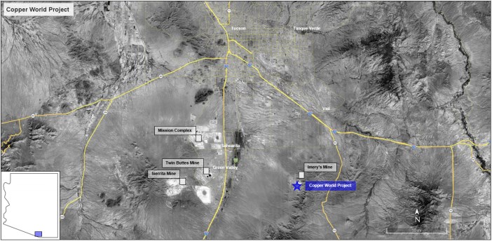
5.2 Climate
The southern Arizona climate is typical of a semi-arid continental desert with hot summers and temperate winters. The Project area topography ranges from flat to mountainous, with the flanks of the Santa Rita Mountains to the northeast and northwest. Surface elevation ranges from 4,265 to 6,280 feet (1,300 to 1,914 m) above mean sea level.
Summer daily high temperatures are above 90°F (32°C) with significant cooling at night. Winter is typically drier, with mild daytime and overnight temperatures typically above freezing. Winter can have occasional low-intensity rainstorms and light snowfall patterns that can last for several days.
|
The average annual precipitation in the Project area is 20 inches (50 cm) based on historical data from eight meteorological stations within a 30-mile (48 km) radius of the Project area. More than half of the annual precipitation occurs during the monsoon season, which lasts from July through to September. The monsoon season is characterized by afternoon thunderstorms typically of short duration, but with high-intensity rainfall that can have minor effects on a mining operation. The lowest precipitation months are April to June.
As with Hudbay's other operations, the Project is subject to the physical risks of climate change, which may arise in the future and could include more frequent extreme weather events, such as extreme dry heat, increased frequency of storms, and reduced water availability. For further information regarding such risks, please see Hudbay's most recent annual information form and management's discussion and analysis available on its SEDAR+ and EDGAR profiles.
5.3 Local Resources
The largest city near the Project area is Tucson, with a population of 542,000 to 548,000 within the city limits. The Tucson Metropolitan Area has a population of over one million.
Arizona is responsible for approximately 68% to 71% of total domestic copper production, and Tucson is a mining industry hub with nine operating copper mines within a 125-mile (200 km) radius. The cultural and educational facilities provided in the Tucson Metropolitan Area attract experienced technical staff into the area. The Tucson Metropolitan Area is home to a well-established base of contractors and service providers for the mining industry.
5.4 Infrastructure
The state and interstate highway systems allow access to the Project site for all major truck deliveries. Much of the labor and supplies for construction and operations can come from the surrounding areas in Pima, Cochise, and Santa Cruz Counties.
The Union Pacific mainline east-west railroad route passes through Tucson, Arizona and generally follows Interstate I-10. The Port of Tucson has rail access from the Union Pacific mainline, consisting of a 2-mile (3.2 km) siding, complemented by an additional 3,000-foot (914 m) siding.
The Tucson International Airport ("TIA") is located 30 miles (48 km) from the Project site and near Interstate highways I-10 and I-19. TIA provides international air passenger and air freight services to businesses in the area, with seven airlines currently providing nonstop service to 15 destinations, and connections worldwide.
The power to the Project will be supplied by Tucson Electric Power (TEP) under a shared service agreement with Trico Electric Cooperative Inc. (TRICO). Since the electrical load for the mining and process operations will be within both the TEP and TRICO service territories, a joint venture business arrangement is expected to be established between both companies to compensate each service provider appropriately, with review and approval by the Arizona Corporation Commission (ACC). Currently, Trico services the Helvetia Site Office with a distribution line that runs through the property. A new transmission line will be built to bring power to the site and service the Project. For further description see Section 18.
|
5.5 Physiography
The Project is located within the northern portion of the Santa Rita Mountains in the Basin and Range Physiographic Province of the southwestern United States. The province is characterized by high mountain ranges adjacent to alluvial-filled basins. The Basin and Range province has been further divided into the Mexican Highlands and Sonoran Desert sub-provinces. The Santa Rita Mountains form the boundary between the Mexican Highlands of southeastern Arizona and the Sonoran Desert sub-province to the West.
The Project occupies relatively flat to mountainous topography on the northeastern and northwestern flanks of the Santa Rita Mountains. The Santa Rita Mountains separate the Cienega Basin to the east from the Santa Cruz Basin to the west.
Vegetation in the Project area reflects the climate of the lower slopes of the Santa Rita Mountains. This area covers three main vegetation communities: the Desert (Scrub) Grasslands, the Desert and Semi-Desert Grasslands, and the Oak, Juniper, Pinyon Community. As the elevation increases in the Project area, vegetation density also increases and transitions into semi-desert grassland that supports abundant catclaw acacia, and mimosa, ocotillo, and yucca.
|
6 HISTORY
The early history and production from the Property has been described in (Anzalone, 1995), (M3 Engineering and Technology Corporation, 2012), (Briggs, 2014), and (Briggs, 2020), from which the following summarization is taken. Hudbay considers the mineral reserve and resource estimates referred to in this section prior to Hudbay's ownership to be historical in nature since no work was done by a qualified person to verify such estimates and such estimates should not be relied upon.
6.1 Helvetia Mining District (1875-1973)
The first recorded mining activity in the Helvetia-Rosemont mining district occurred in 1875. The Helvetia mining district was officially established in 1878. Production from mines on both sides of the Santa Rita ridgeline supported the construction and operation of the Columbia Smelter in Helvetia and the Rosemont Smelter in Old Rosemont (Figure 6-1).
Figure 6-1: Location of Historical Mine in the Helvetia Mining District
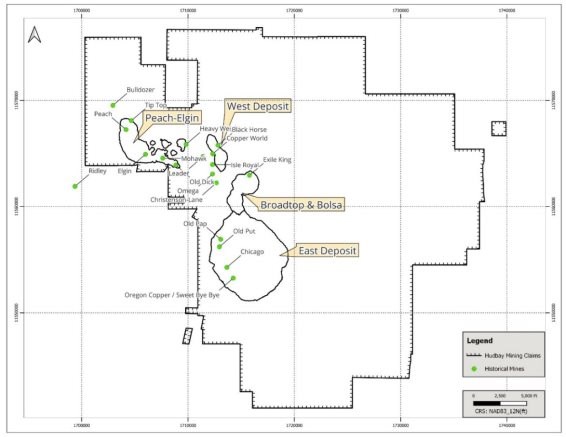
|
Copper production from the district ceased in 1961 after production of about 438,000 tons of ore containing 36,766,000 pounds of copper, 1,130,000 pounds of zinc and 361,600 ounces of silver (Table 6-1).
Table 6-1: Production History of the Helvetia District 1875-1969 After (Briggs, 2020)
| Mine Name | Years | Ore Treated Tons | Copper (lbs.) | Lead (lbs.) | Zinc (lbs.) | Gold (Troy oz) |
Silver (Troy oz) |
| Bulldozer | 1882 - 1960 | 6,700 | 613,000 | 0 | 0 | 8 | 6,450 |
| Copper World | 1900 - 1960 | 17,400 | 1,777,000 | 0 | 0 | 49 | 15,530 |
| Elgin | 1901 - 1960 | 90,900 | 4,267,000 | 0 | 0 | 555 | 33,050 |
| King-Exile | 1913 - 1959 | 69,600 | 8,158,000 | 66,000 | 376,700 | 33 | 93,060 |
| Leader | 1885 - 1944 | 35,100 | 3,720,000 | 0 | 0 | 154 | 34,740 |
| Mohawk | 1885 - 1948 | 36,600 | 2,676,000 | 3,000 | 28,020 | 32 | 7,330 |
| Narragansett-Daylight | 1907 - 1961 | 97,100 | 8,441,000 | 143,000 | 254,800 | 59 | 63,470 |
| Old Dick | 1940 - 1952 | 12,000 | 893,000 | 0 | 0 | 88 | 7,730 |
| Omega | 1875 - 1920 | 6,700 | 718,000 | 42,000 | 0 | 0 | 7,990 |
| Peach | 1916 - 1952 | 11,100 | 1,175,000 | 4,000 | 460,190 | 2 | 8,940 |
| Tip Top | 1899 - 1956 | 27,400 | 2,766,000 | 0 | 0 | 6 | 11,190 |
| Other Producers (22) | 1881 - 1969 | 26,700 | 1,572,000 | 113,000 | 8,790 | 283 | 72,110 |
| District Total | 1875 - 1969 | 438,000 | 36,776,000 | 372,000 | 1,130,000 | 1269 | 361,600 |
By the late 1950s, the Banner Mining Company (Banner) had acquired most of the claims in the area and had drilled the discovery hole into the East Deposit. In 1963, the Anaconda Mining Co. acquired options to lease the Banner holdings and over the next ten years they drilled 113 holes on both sides of the mountain. The exploration program demonstrated that a large-scale porphyry/skarn existed at the East Deposit. Regional exploration also identified targets at the Broadtop Butte and Peach-Elgin prospects. In 1964, Anaconda produced a historical resource estimate for the Peach-Elgin deposit located in the Helvetia District. Based on assays from 67 churn and diamond drill holes, the estimate identified 14 million tons of sulfide material averaging 0.78% copper and 10 million tons of oxide material averaging 0.72% copper. The 1964 historical resource estimate prepared by Anaconda is treated by Hudbay as historical. Hudbay is not treating it as current, and it should not be relied upon. Instead, reference should be made to the Mineral Resource estimates that are the subject of this Technical Report.
6.2 Anamax Mining Company (1973-1985)
In 1973, Anaconda Mining Co. and Amax Inc. formed a 50/50 partnership to form the Anamax Mining Co. In 1977, following years of drilling and evaluation, the Anamax joint venture commissioned the mining consulting firm of Pincock, Allen & Holt, Inc. to estimate a resource for the East Deposit. Their historical resource estimate of about 445 million tons of sulfide mineralization averaged 0.54% copper, using a cut-off grade of 0.20% copper. In addition to the sulfide material, 69 million tons of oxide mineralization averaging 0.45% copper was estimated. Subsequent engineering designed a pit based on 40,000 tons/day production rate for a mine life of 20 years.
|
In 1979, Anamax carried out a resource estimate for the Broadtop Butte deposit located about one mile north of the East Deposit. Based on assays from 18 widely spaced diamond drill holes, a historical estimate identified 9 million tons averaging 0.77% copper and 0.037% molybdenum. In 1985, Anamax ceased operations and liquidated their assets. Today, most of the Anaconda/Anamax core is currently stored at Hidden Valley core storage facility at the Project site.
The 1973 and 1979 historical resource estimates prepared by Anamax are treated by Hudbay as historical. Hudbay is not treating them as current, and they should not be relied upon. Instead, reference should be made to the Mineral Resource estimates that are the subject of this Technical Report.
6.3 Asarco Incorporated (1988-2004)
Asarco purchased the patented and unpatented mining claims in the Helvetia-Rosemont mining district from real estate interests in August 1988, renewed exploration of the Peach-Elgin deposit, and initiated engineering studies on the East deposit. In 1994, Asarco succeeded in acquiring patents on 21 mining claims in the Rosemont area just prior to the effective date of the moratorium placed on patenting mining claims in 1994.
In 1999, Grupo Mexico acquired the Helvetia-Rosemont property through a merger with Asarco. During the 16 years of ownership by Asarco and Grupo Mexico, 11 diamond drill holes were completed. Asarco estimated historical reserves of 294,834,000 tons at 0.673% copper based on a mine production schedule with a strip ratio of 3.7:1. In 2004, Grupo Mexico sold the property to a Tucson developer.
The historical reserve estimate prepared by Asarco is treated by Hudbay as historical. Hudbay is not treating it as current, and it should not be relied upon. Instead, reference should be made to the Mineral Reserve estimates that are the subject of this Technical Report.
6.4 Augusta Resource Corporation (2005-2014)
In April 2005, Augusta purchased the property from Triangle Ventures LLC. Between mid-2005 and January 2007, Augusta drilled 55 diamond drill holes to bring the resource estimate into compliance with NI 43-101 standards. The program was designed to better define the geology, distribution of copper mineralization, as well as gather geotechnical data required for mine design. In June 2006, the Washington Group Int. completed a preliminary assessment and economic evaluation of the Rosemont Copper Project.
Over the next several years, Augusta continued to evaluate the mineral potential and refine the economics of developing this resource. Thirty-two (32) additional drill holes were drilled between 2007 and 2012 and a Technical Report was issued by Augusta in 2012 to support mineral resource and mineral reserve estimates. Augusta's mineral resource estimates were based on a Feasibility Study in respect of a distinct development for the East Deposit (known at the time as the Rosemont Copper Project). In 2010, Rosemont Copper Company, an affiliate of Augusta, entered into an offtake agreement in respect of a portion of the copper concentrate production that was anticipated from the Rosemont Copper Project as part of an offtake financing arrangement to assist with the development of that project. Augusta's attempted development of the Rosemont project involved a complex federal permitting process, a joint venture, a precious metals streaming arrangement, and the offtake financing arrangement was entered into to help fund the Rosemont Copper Project through federal permitting and development.
|
The historical reserve and resource estimates prepared by Augusta are treated by Hudbay as historical. Hudbay is not treating such estimates as current, and they should not be relied upon. Instead, reference should be made to the Mineral Reserve and Mineral Resource estimates that are the subject of this Technical Report.
6.5 Hudbay (2014-Present)
Following its acquisition of Augusta in 2014, Hudbay repaid all amounts that were owing under Augusta's offtake financing arrangement and added 89 drill holes between September 2014 and November 2015 in further efforts to gain a better understanding of the geological setting and mineralization of the East Deposit, and to collect additional metallurgical and geotechnical information.
Drilling conducted by Hudbay was used in combination with previous drilling campaigns to build resource models that supported a Feasibility Study completed and documented in a 2017 technical report (the "2017 Technical Report"). The 2017 Technical Report included an estimate of the mineral reserves and mineral resources at the East Deposit that have since been superseded.
While litigation over the federal permits that Augusta had applied for in respect of the Rosemont Copper Project was ongoing, Hudbay commenced a comprehensive review of the exploration potential of the entire land package it acquired from Augusta, along with the East Deposit, in 2014. Drilling conducted in 2020 and 2021 resulted in the discovery and delineation of multiple additional deposits, in an almost continuous manner over a 7 km strike length adjacent to the East Deposit. Drilling by Hudbay continued through December of 2022.
Exploration successes on these patented mining claims and ongoing litigation uncertainty regarding the initial project contemplated by the 2017 Feasibility Study led Hudbay to make significant investments to evaluate alternative design and development options to unlock value within this prospective district, and to eventually abandon the Rosemont Copper Project and its permits. The Rosemont Copper Project was therefore never developed, and Augusta's historical offtake agreement for the Rosemont Copper Project does not apply to the Copper World Project.
In addition, in 2019, Hudbay reached an agreement to purchase United Copper & Moly LLC's (''UCM'') minority interest in Copper World. At the time, UCM owned a 7.95% interest in the Copper World Project and could have earned up to a 20% joint venture interest, pursuant to an earn-in and joint venture agreement that it had entered into with Augusta in 2010. After completing the purchase, Hudbay indirectly held a 100% interest in Copper World.
Following the completion of the 2022 PEA, Hudbay conducted an extensive infill drill program over the areas hosting the mineral resource estimates that were included in Phase I of the 2022 PEA, as well as new metallurgical testing. This led to the completion and publication of a PFS contemplating a single phase 20-year mine plan based on mineral reserves only and excluding Extension Case expansion onto federal lands. The mineral resource estimates that were part of the second phase of the 2022 PEA were also updated.
Table 6-2 lists the Mineral Reserve estimates that were included in the 2023 PFS, which are now superseded by the Mineral Reserve estimates that are the subject of this Technical Report.
|
Table 6-2: Proven & Probable Mineral Reserve Estimates (2023 PFS)
| Metric tonnes (in million) |
Short tons (in million) |
Cu% | CuSS% | Mo (ppm) |
Mo (Troy oz per ton) |
Ag (ppm) |
Ag (Troy oz per ton) |
Au (ppm) |
Au (Troy oz per ton) |
|
| Proven | 319.4 | 352.1 | 0.54 | 0.11 | 110 | 3.21 | 5.675 | 0.17 | 0.03 | 0.0008 |
| Probable | 65.7 | 72.4 | 0.52 | 0.14 | 96 | 2.81 | 4.305 | 0.13 | 0.02 | 0.0006 |
| Total | 385.1 | 424.5 | 0.54 | 0.12 | 108 | 3.14 | 5.441 | 0.16 | 0.02 | 0.0007 |
Notes: 1. Totals may not add up correctly due to rounding. 2. Mineral Reserve estimates as of 1 July 2023. 3. Mineral Reserve estimates are limited to the portion of the measured and indicated resource estimates scheduled for milling and included in the financial model of this PFS. 4. Mineral reserves have been calculated using assumed long-term metal prices of $3.75 per pound copper, $12 per pound molybdenum, $22 per ounce silver, and $1,650 per ounce gold.
Table 6-3 summarizes the 2023 PFS mineral resource estimates exclusive of the measured and indicated mineral resources estimates that had been converted to mineral reserve estimates. These mineral resource estimates which are now superseded by the Mineral Resource estimates that are the subject of this Technical Report included resource estimates located within the mineral reserve pit but not processed within the mine life of the PFS and as such excluded from the mineral reserve estimates but still deemed to have potential for economic extraction with additional infill drilling and/or additional metallurgical test work.
Table 6-3: Mineral Resource Estimate (Exclusive of Mineral Reserves) - 2023 PFS
| Category | Metric Tonnes (in million) |
Short tons (in million) |
Cu% | CuSS% | Mo (ppm) |
Mo (Troy oz per ton) |
Ag (ppm) |
Ag (Troy oz per ton) |
Au (ppm) |
Au (Troy oz per ton) |
||
| EXCLUSIVE | Flotation Material |
Measured | 424 | 467 | 0.39 | 0.04 | 150 | 4.38 | 4.1 | 0.12 | 0.022 | 0.0007 |
| Indicated | 191 | 210 | 0.36 | 0.06 | 125 | 3.64 | 3.5 | 0.10 | 0.016 | 0.0005 | ||
| M+I | 614 | 677 | 0.38 | 0.05 | 142 | 4.15 | 4.0 | 0.12 | 0.020 | 0.0006 | ||
| Inferred | 192 | 211 | 0.35 | 0.07 | 117 | 3.40 | 3.1 | 0.09 | 0.013 | 0.0004 | ||
| Leach Material |
Measured | 159 | 176 | 0.28 | 0.20 | - | - | - | - | - | - | |
| Indicated | 70 | 77 | 0.26 | 0.20 | - | - | - | - | - | - | ||
| M+I | 229 | 253 | 0.27 | 0.20 | - | - | - | - | - | - | ||
| Inferred | 83 | 92 | 0.26 | 0.19 | - | - | - | - | - | - |
Notes: 1. Totals may not add up correctly due to rounding. 2. Mineral resources are estimated as of 1 July 2023. 3. Tons and grades constrained to a Lerchs-Grossman revenue factor 1 pit shell or inside reserve pit. 4. Using a 0.1% copper cutoff grade and an oxidation ratio lower than 50% for flotation material. 5. Using a 0.1% soluble copper cutoff grade and an oxidation ratio higher than 50% for leach material. 6. Mineral resources are not mineral reserves as they do not have demonstrated economic viability. 7. Mineral resource estimates are exclusive of mineral reserves and have been calculated using assumed long-term metal prices of $3.75 per pound copper, $12 per pound molybdenum, $22 per ounce silver, and $1,650 per ounce gold.
In January 2026, Hudbay and Mitsubishi entered into a Joint Venture Agreement in respect of Mitsubishi's 30% investment in Copper World. On closing of the Copper World joint venture transaction, Mitsubishi contributed approximately $420M of cash to Copper World LLC, and it will contribute an additional $180M in cash to complete its initial investment within 18 months of closing in accordance with the terms of the definitive transaction documents. Mitsubishi will also fund its pro-rata 30% share of future equity capital contributions required to construct Copper World.
|
7 GEOLOGICAL SETTING & MINERALIZATION
7.1 Regional Geology
The Copper World Project deposits are in the Laramide belt, a major porphyry province that extends for approximately 600 miles (965 km) from Arizona to Sinaloa, Mexico (Figure 7-1) and includes several other world-class deposits (e.g., Morenci, Resolution, and Cananea). Mesozoic subduction and associated magmatism and tectonism in the southwestern United States and northern Mexico generated extensive and relevant porphyry copper mineralization. Compressional tectonism during the Mesozoic and early Cenozoic Laramide Orogeny caused folding and thrusting, accompanied by extensive calc-alkaline magmatism (Barra, 2005). Tertiary extensional tectonism followed the Laramide Orogeny, accompanied by voluminous felsic volcanism (Barra et al., 2005). Tertiary faulting juxtaposed mineralized and unmineralized rocks. The extensional tectonics culminated in the large-scale block faulting that produced the present basin and range geomorphology that is typical throughout southern Arizona (Maher, 2008).
Figure 7-1: Laramide Belt & Associated Porphyry Copper Mineralization (Barra, 2005)
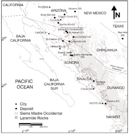
|
7.2 District Geology
The Project deposits sit within the northern block of the Santa Rita Mountains in southern Arizona (Figure 7-2). As reviewed by Ramussen et al. (2012), the northern block is dominated by Precambrian granite (brown on the map), with slices of Paleozoic and Mesozoic sediments on the eastern and northern sides (blue, green, and yellow on the map). This block includes small stocks and dikes of quartz monzonite or quartz latite porphyry that are related to porphyry copper and skarn mineralization; and broader, more equigranular, Tertiary, granitic intrusive stocks. Tertiary faulting appears to have significantly segmented the original stratigraphy and deposits, juxtaposing mineralized and unmineralized rocks.
Figure 7-2: Project Regional Geology
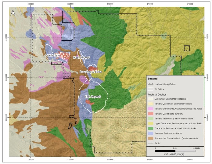
|
7.3 Deposit Geology
Since 2014, Hudbay's drilling programs have included complete multi-element assays for every sample. This extensive database was used to classify the different stratigraphic units according to their geochemical affinities induced by mixing of siliciclastic, dolomitic, and calcareous sediments as well as a hydrothermal component. This grouping ultimately reflects the mineralogy as illustrated on a cross-section through the East Deposit (Figure 7-3).
Figure 7-3: East Deposit - Vertical Geological Section 11,555,050' N, Looking North
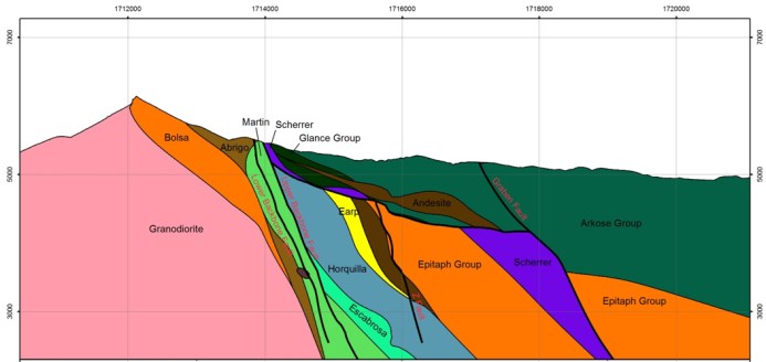
The predominantly carbonate Paleozoic units are the main host rocks for the copper mineralization in the district excluding the Broadtop Butte and Elgin deposits. At the East Deposit, Mesozoic clastic units structurally overlie the Paleozoic sequence; in contrast the Paleozoic sequence in all other deposits are generally exposed or near the surface. Quartz monzonite porphyries (QMP) are the predominant host of copper mineralization at the Broadtop Butte and Elgin deposits (Figure 7-4 and Figure 7-5).
|
Figure 7-4: Peach-Elgin Deposit - Vertical Geological Section (Simplified) 11,656,200'N, Looking North
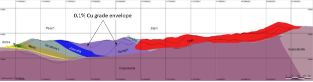
Figure 7-5: Broadtop Butte Deposit - Vertical Geological Section 11,562,000' N, Looking North
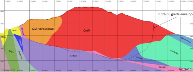
7.4 Alteration
The Project deposits consist of copper-molybdenum-silver-gold mineralization primarily hosted in skarn. Skarn formed in the Paleozoic rocks from mineralizing fluids related to the intrusion of quartz latite to quartz monzonite porphyry intrusions. Bornite-chalcopyrite-molybdenite mineralization occurs as veinlets and disseminations.
Garnet-diopside-wollastonite skarn, which formed in impure limestone, is the most important skarn type volumetrically. Diopside-serpentine skarn, which formed in dolomitic rocks is less significant. Marble was developed in the purest carbonate rocks, while the more siliceous, silty rocks were converted to hornfels; both marble and hornfels are relatively poor hosts to mineralization. The main skarn minerals can be accompanied by quartz, amphibole, magnetite, epidote, chlorite, and clay minerals. Quartz latite to quartz monzonite intrusive rocks host strong quartz-sericite-pyrite alteration with minor mineralization. Where the mineralized package of Paleozoic rocks and quartz latite intrusive outcrop on the western side of the deposit, near-surface weathering and oxidation has produced disseminated and fracture-controlled copper oxide minerals.
|
The Mesozoic and lesser Paleozoic rocks above the low-angle fault at the East Deposit show a propylitic alteration to an assemblage including epidote, chlorite, calcite, and pyrite; copper mineralization is irregularly developed. The rocks are commonly deeply weathered and limonitic. The original chalcopyrite is typically oxidized to chrysocolla, copper wad and copper carbonates; supergene chalcocite is locally present.
7.5 Structural Domains
The geological model incorporated a structural framework based on a surface and downhole structural review. The temporal and special relations between the main fault surfaces define 5 structural domains at the Project: Backbone Footwall, Lower Plate, Upper Plate, Graben Block and the Helvetia Thrust klippe (Figure 7-6).
Figure 7-6: Project Deposit Geological Model Structural Domains & Major Lithologies Plan View
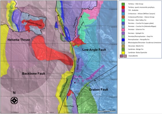
The north trending, steeply dipping Backbone Fault juxtaposes Precambrian granodiorite and Lower Paleozoic quartzite and limestone to the west (Backbone Footwall block) against a block of an homoclinical sequence of younger, mineralized, metamorphosed sedimentary units to the east (Lower Plate).
The Backbone Fault generally strikes north-south at the East Deposit and continues north, slightly east of the ridgeline, crossing to the west side of the ridgeline west of Broadtop Butte. The Lower Paleozoic quartzite (Bolsa Formation) and limestone (Abrigo and Martin Formations) are well mineralized in the Backbone Footwall. North of Broadtop Butte, the Backbone Fault shifts to the northwest to constitute the controlling feature of the mineralization at the West deposit.
|
The Low Angle Faults at the East Deposit are a series of shallowly east-dipping faults that consist of one major fault and a series of steep to shallow splay structures. The main Low Angle Fault forms the non-conformable contact between the Upper Plate (siliciclastics and volcanics) and the Lower Plate (carbonate dominant, Paleozoic rocks) structural domains at the East Deposit.
The Graben Fault is a significant, late, high-angle fault at the very southeastern margin of the East Deposit which appears to truncate mineralization. No significant mineralized domains exist inside the Graben Fault Hanging Wall.
Within the Upper Plate Domain, a mass of quartz-monzonite porphyry comprises the core of the Broadtop Butte Deposit. Within Broadtop Butte, a generally east-northeast breccia pipe sits along the southern margin of the quartz monzonite porphyry with skarn and limestone clasts.
The fifth major structural domain, the Helvetia Thrust Klippe, is on the western slope of the Santa Rita Mountains. The low-angle Helvetia Thrust Fault places Laramide-aged quartz monzonite porphyry, intruded Paleozoic-aged carbonate, and clastic sequences atop intrusive equigranular to seriate granitic rocks. A north-striking, high angle fault occurs between the sedimentary-hosted Peach Deposit on the west side, and the quartz monzonite porphyry and skarn margin dominant Elgin deposit to the west. Although, mineralization does appear to occur in continuity across this fault.
Figure 7-7: East Deposit Geological Model of Structural Domains 3D View, Looking North
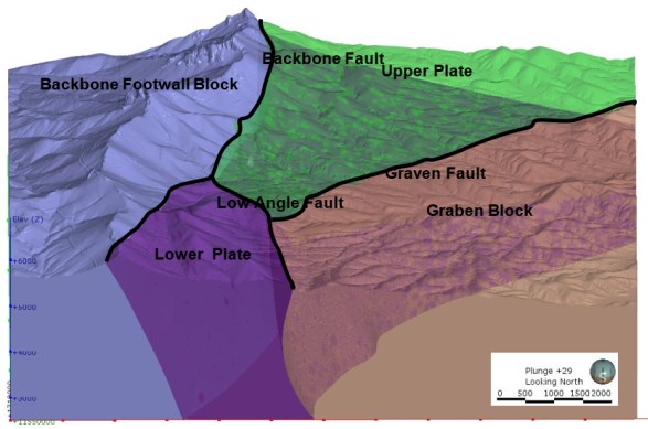
|
7.6 Mineralization
Mineralization occurs as both copper oxides and sulfides in skarns and intrusive porphyry rock. A 3D model of five mineralization domains was completed based on analytical data, including the hole acid soluble data, and Quemscan analysis collected by Hudbay from the East, Bolsa, Broadtop Butte, West and Peach-Elgin deposits.
7.6.1 East Deposit
The East Deposit ranges between 3,400 to 5,600 feet in diameter and extends to a depth of approximately 2,600 feet below the surface. The main fault systems partially delimit copper mineralization, dividing the deposit into major structural blocks with contrasting intensities, and types of mineralization (Figure 7-7). The north-trending, steeply dipping Backbone Fault juxtaposes marginally mineralized Precambrian granodiorite and Lower Paleozoic quartzite and variably mineralized limestone to the west (Backbone Footwall Block), against a block of younger, well-mineralized, Paleozoic limestone units to the east (Lower Plate). The Graben Fault on the southeast side of the East Deposit truncates significant mineralization.
Oxidized copper mineralization is present in the upper portion of the deposit. The oxidized mineralization is primarily hosted in Mesozoic rocks but is also found in Paleozoic rocks on the west side of the deposit, and deeper along some faults. The oxidized mineralization occurs as mixed copper oxide and copper-carbonate minerals. Locally, enrichment of supergene chalcocite and associated secondary mineralization are found in and beneath the oxidized mineralization. Oxide copper in the northwest of the East Deposit extends considerably at depth on fractures within the Backbone Footwall.
Primary (hypogene) mineralization occurs mostly in the form of copper, molybdenum, and silver-bearing sulfides, found in stockwork veinlets and disseminated in the altered host rock. Pyrite and chalcopyrite comprise approximately 25% and 35% of the total sulfides content, respectively; along with bornite (20%) and chalcocite (12%). The ratio of these main sulfide minerals is variable through the stratigraphy of the deposit. Molybdenite is a minor phase but appears to be distributed throughout the skarn and in peripheral portions of the deposit. Gold and silver are present in small amounts across the deposit and are thought to be contained in the primary sulfide minerals.
7.6.2 Broadtop Butte Deposit
Drilling at Broadtop Butte has defined a mineral resource 1,600 to 2,500 feet in diameter and up to 800 feet thick. Mineralization is predominantly hosted by quartz monzonite porphyry, including an east-northeast striking brecciated zone. Skarns hosted in the Arkose Group and Glance group to the south of the quartz monzonite, and in the Glance Group, Scherrer Formation and Epitaph Formation to the north, east and below the quartz monzonite also host mineralization. Mineralization appears to be truncated on the east by the Backbone Fault. The extent of mineralization in all other directions does not appear to have strict stratigraphic or structural boundaries but seems to be related to the distance from the quartz monzonite porphyry and its associated skarn alteration halo. Mineralization in the unbrecciated quartz monzonite porphyry is dominated by sulfide mineralization, however, oxide copper mineralization is dominant in the breccia pipe portion of the quartz monzonite porphyry. Skarns at depth to the north and northeast of the quartz monzonite porphyry are relatively narrow, but with higher-grade sulfides.
|
7.6.3 West Deposit
The West deposit mineralization strikes at approximately 160°, parallel to the Backbone Fault for 3,200 feet. It ranges from 400 to 1,100 feet wide, and 300 to 700 feet deep. Mineralization is hosted by Paleozoic quartzites, and skarn altered carbonate units on both the footwall and hanging wall of the Backbone Fault domain. In the northern half of the deposit, mineralization is also hosted in fractured coarse granitic rocks in the Backbone Fault domain footwall. The strongest mineralization is within the Backbone Fault structural zone and is dominated by sulfide mineralization. The Hanging Wall of the main Backbone structure has lower grades and is oxide dominated. The major host stratigraphies at the West deposit are the Precambrian coarse granitic rocks within the Backbone Fault Zone, and Paleozoic formations from Bolsa to Epitaph (footwall and lower plate units at the West Deposit). Mineralization nearly reaches the surface on the west slope of the low mountain that hosts most of the West deposit. Eastward no distinct structural or stratigraphic features limit mineralization. Drilling has defined the southern extent of mineralization, although the extent of mineralization to the north has not been completely defined.
7.6.4 Peach-Elgin Deposit
The Peach-Elgin mineralization is hosted in the hanging wall of the low-angle Helvetia Thrust Fault (Helvetia Klippe) which hosts several historically mined deposits including the Peach, Elgin, Mohawk, Old dick, and Heavy Weight mines. Drill holes, both historical and recent, have connected much of the Helvetia Thrust hanging wall mineralization.
Peach is entirely hosted in variably skarn-altered sedimentary rocks and is cut by moderately shallow, east dipping faults, producing gaps in the stratigraphic sequence. Host stratigraphies include Bolsa, Abrigo, Martin, Escabrosa, Horquilla, and Epitaph. The Peach mineralization hosts an irregularly intertwined mix of copper oxide and copper sulfide dominated units.
The Helvetia Thrust mineralization, east of Peach, is hosted within the quartz monzonite porphyry, or in the skarn altered halo around the porphyry, primarily in the Epitaph and Concha Formations. A very narrow massive sulfide has been intercepted in the northeast of the Helvetia Thrust hangingwall; however the bulk of mineralization is disseminated in the porphyries, or in broader, marginal skarns.
|
8 DEPOSIT TYPE
The Project deposits consist of copper-molybdenum-silver-gold mineralization hosted in quartz monzonite porphyries, and in skarn. The skarn formed in the Paleozoic rocks from fluids associated with quartz latite to quartz monzonite porphyry intrusions. Genetically, skarns form part of the suite of deposit styles associated with porphyry copper centers. The skarns were formed as the result of thermal and metasomatic alteration of Paleozoic carbonate and, to a lesser extent, Mesozoic clastic rocks. Near-surface weathering has resulted in the oxidation of the sulfides in the overlying Mesozoic units at the East Deposit, and in the near-surface Paleozoic units of the Copper World deposits.
Mineralization occurs mostly in the form of primary (hypogene) copper, molybdenum, and silver-bearing sulfides, found in stockwork veinlets and disseminated in the altered host rock at depth. Near the surface, along structural zones, and in quartzite units, oxidized copper mineralization is present. The oxidized mineralization occurs as mixed copper oxide and copper carbonate minerals. Locally, enrichment of supergene chalcocite and associated secondary mineralization are found in and beneath the oxidized mineralization.
For the 2026 Definitive Feasibility Study, a model of metal deportment for copper by type of mineral was added to the resource model. This was done in order to better reflect the results from the extensive metallurgical testing program complemented with extensive mineralogical characterization and flotation tests as described in Section 13 of this report. A machine learning model based on a random forest algorithm described in detail in Section 14 of this report was developed to estimate the proportion of the copper occurring in 6 different groups of minerals, including copper wads, Goethite, carbonates, oxides, primary and secondary sulfides. While most of the copper mineralization occurs as primary and secondary sulfides (Chalcopyrite-Bornite-Chalcocite), copper can be present in the other mineralization assemblages along structures or lithological contacts and in the upper part of the Broadtop, West and Peach deposits.
The Twin Buttes Mine, operated by Anaconda and later by Cyprus, was developed on a deposit with several geologic similarities, located approximately 32 km to the west of the Project. The Twin Buttes mine was in production from 1969 to 1994. In addition, the Asarco Mission Mine, located approximately 32 km to the west of the Project, also has many geologic characteristics in common with the Copper World deposits.
|
9 EXPLORATION
9.1 Previous Work
Prospecting began in the Rosemont and Helvetia Mining Districts in the mid-1800s and by 1875 copper production was first recorded, which continued sporadically until 1951. By the late 1950s, exploration drilling had discovered the East Deposit. A succession of major mining companies subsequently conducted exploratory drilling of the East Deposit and the nearby Broadtop Butte, Peach-Elgin, and Copper World mineralized areas.
Augusta acquired the property in 2005 and performed infill drilling at the East Deposit, along with exploration geophysical surveys. A Titan 24 induced polarization/resistivity ("DCIP") survey over the East Deposit, performed in 2011, discovered significant chargeability anomalies which are only partially tested to date. These anomalies appear to define mineralization and certain unmineralized lithologic units. A regional scale airborne magnetics survey was also completed in 2008 to aid in geological mapping of the property and outline the magnetic footprint of the deposit.
Two infill drilling campaigns were completed by Hudbay in and beneath the East Deposit in 2014 and 2015. In addition to chemical assaying, magnetic susceptibility and conductivity measurements were taken using the Terraplus' KT-10 & KT-20 instruments at approximately 3-meter (10-feet) intervals of recovered core from the drilling program. The magnetic susceptibility data has been used from both drilling programs as a constraint for a 3D inversion of the deposit. A single test-line of DCIP data was collected over the East Deposit using the DIAS Geophysical (3D Survey/Mapping) in April 2015 for comparison to the previously completed Titan 24 survey.
A mapping and geochemical sampling program was completed in the latter half of 2015 on the property to reassess the interpretation of the regional geology and deposit setting. This was followed by a structural interpretation using both surface and drill core measurements to aid in the geotechnical evaluation of the Project. Magnetic susceptibility and conductivity measurements were taken using the Terraplus' KT-10 & KT-20 instruments at the same locations as the geochemical samples.
In October 2020, a 47 line-km Versatile Time-Domain Electromagnetic (VTEM) test survey was completed over the property on 10 east-west & 2 north-south lines to determine if this method is appropriate to aid in the delineation of poor to moderately conductive skarn material in the area. In general, the results highlighted lithological units rather than specific mineralization hosted in skarn deposits.
During the fall 2020 field program, five drillholes were surveyed by DGI Geoscience Incorporated using Acoustic & Optical Televiewer downhole equipment. These surveys were completed to identify features (joints, bedding, etc.) to aid in the structural interpretation of the intersected geological units as well as highlight faults or shear zones.
From January to April 2021, Quantec Geoscience Incorporated using their Titan 24 induced polarization/resistivity ("DCIP") method surveyed 50.3 line-km over thirteen east-west lines. Additional significant chargeable anomalies were identified and are only partially tested to date. This survey is meant to be an expansion of the 2011 program.
|
Hudbay initiated exploration drilling on targets within its Copper World private land in October 2020. Drill targets proximal to the historical mines included the Elgin, Copper World, Leader, Isle Royale, and King Mines; historically identified drill targets included Broadtop Butte and Peach; and previously undrilled targets, most notably the Bolsa area.
9.2 Exploration Potential Between, & Proximal to, Known Deposits
The West deposit remains open to the north. Broadtop Butte's mineralized extent has not been fully defined at depth in the east or south of the deposit. The Peach-Elgin deposit remains open in the north towards Hudbay's unpatented mining claims. The extent of mineralization along western edge of the East deposit has been constrained at shallow depths but remains open at depth.
Several geophysical targets exist outside of the known deposits. The most notable are a pair of anomalies approximately 1,400 feet north of the known West deposit on Forest Service land where Hudbay holds unpatented mining claims. Limited transects have identified numerous small exploration pits within this region, however the anomalies have never been drill tested. Additional untested anomalies include those east of Broadtop Butte.
9.3 Additional Regional Potential on Hudbay Tenements
Additional potential targets not currently covered by IP coverage exist on Hudbay unpatented mining claims. These include targets proximal to historical mines, and mapped QMP intrusions. Some of these intrusions were mapped by the USGS (Drewes, 1971) as the same intrusive unit that hosts porphyry mineralization at both Broadtop Butte and Elgin. All these targets would benefit from detailed mapping, ground-penetrating geophysics, and drilling.
|
10 DRILLING
Extensive drilling has been conducted by several successive property owners. The most recent drilling was done by Hudbay Minerals Inc., with prior campaigns completed by Lewisohn, Banner, Anaconda Mining Co., Anamax, Asarco and Augusta. Table 10-1 summarizes the drill holes used to estimate the current mineral resource estimate.
Table 10-1: Drillhole Database for the Project
| Churn | Rotary | RC | DDH | All DH Types | |||||||||||||
| Company | Time Period | Holes | (m) | (ft) | Holes | (m) | (ft) | Holes | (m) | (ft) | Holes | (m) | (ft) | Holes | (m) | (ft) | |
| Lewishon | 1956 | 1957 | 28 | 3,042 | 9,980 | - | - | - | - | - | - | 18 | 2,249 | 7,377 | 46 | 5,290 | 17,357 |
| Banner | 1961 | 1963 | - | - | - | - | - | - | - | - | - | 34 | 3,828 | 12,560 | 34 | 3,828 | 12,560 |
| Anaconda | 1961 | 1972 | - | - | - | - | - | - | - | - | - | 210 | 54,376 | 178,399 | 210 | 54,376 | 178,399 |
| Anamax | 1970 | 1983 | - | - | - | 29 | 1,821 | 5,974 | - | - | - | 186 | 39,008 | 127,979 | 215 | 40,829 | 133,953 |
| Asarco | 1988 | 1992 | - | - | - | 1 | 426 | 1,399 | - | - | - | 11 | 4,479 | 14,695 | 12 | 4,905 | 16,094 |
| Augusta | 2005 | 2012 | - | - | - | 34 | 10,002 | 32,815 | - | - | - | 87 | 40,381 | 132,483 | 121 | 50,383 | 165,298 |
| Hudbay | 2014 | 2022 | - | - | - | - | - | - | 146 | 21,687 | 71,150 | 970 | 174,072 | 571,103 | 1,116 | 195,759 | 642,253 |
| Summary | 28 | 3,042 | 9,980 | 64 | 12,249 | 40,188 | 146 | 21,687 | 71,150 | 1,516 | 318,393 | 1,044,596 | 1,754 | 355,371 | 1,165,914 | ||
Some limited additional condemnation, hydrogeological (point of compliance), geotechnical and infill drilling has been conducted by Hudbay since late 2024. Since drilling is aimed at operational readiness, and additional drilling has not brought any material change to the resource model, the drilling database supporting the mineral resource and mineral reserve estimates remain unchanged from the 2023 PFS (Table 10-2).
Table 10-2: Recent Drilling Project in Copper World since 2024 Q4
| Company | Project | Pit | Year | RC | DDH | All DH types | |||
| Objective | Holes | (ft) | Holes | (ft) | Holes | (ft) | |||
| Hudbay | Geotechnical | East, West Pit, BroadTop, PeachElgin | 2024 | 0 | 0 | 16 | 12,260 | 16 | 12,260 |
| Hudbay | Point of Compliance (POC) | East, West Pit, BroadTop, PeachElgin | 2025 | 10 | 2,523 | 0 | 0 | 10 | 2,523 |
| Hudbay | Condemnation | East, West Pit, BroadTop, PeachElgin | 2025 | 26 | 14,760 | 0 | 0 | 26 | 14,760 |
| Hudbay | Infill | West Pit, BroadTop | 2025 | 0 | 0 | 37 | 18,709 | 37 | 18,709 |
The drill holes in the database are mostly diamond drill holes. In some older holes, the top portion was drilled using a rock bit to set the collar, or by rotary drilling methods and then switched to core drilling before intercepting mineralization. Reverse-circulation ("RC") drilling was utilized by Hudbay from 2021 to mid-2022. Although all RC holes are stored in the database, only those within porphyry (Elgin and Broadtop Butte), low copper grade quartzite, and granite were used in resource calculations.
Core recoveries within the mineralized zone for the Hudbay and Augusta drilling programs average over 90%, lending confidence that quality samples were obtained, including the oxidized intervals.
|
A map showing the location of the drill holes by company is provided in Figure 10-1 for the Copper World Project.
Figure 10-1: Drillhole Locations by Company
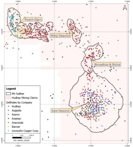
10.1 Lewisohn & Banner Mining Company (1953-1963)
The earliest drilling recorded on the Project area was conducted by Lewisohn between 1953 and 1957 and utilized churn drilling. No material is left from this drilling, and only paper logs and copper assay results are available. This data was validated by conducting a global statistical comparison with recent core drilling done by Hudbay over the same volume.
The first significant core drilling campaign on the Property was by Banner, beginning in about 1961. Banner primarily completed shallow diamond drill holes, many of which were subsequently deepened by Anaconda Mining Co.
|
10.2 Anaconda Mining Company (1963-1986)
Anaconda acquired Banner Rosemont Holdings around 1963 and conducted exploration at the East Deposit as well as in adjacent mineralized areas. Between 1963 and 1973, Anaconda completed 210 diamond drill holes for a total of 178,399 feet (54,376 m). These holes were primarily drilled vertically. Down-hole and collar surveys completed by company surveyors were conducted during drilling or immediately following drill hole completion. Anaconda drilled approximately 85% of these holes as the larger N-size core and 15% as the smaller B-size core (1.4 inch or 36.4 mm diameter). Overall core recovery was more than 85%.
Exploration subsequently transferred to Anamax Mining Company, (an Anaconda Mining Co., and Amax Inc. joint venture), which continued diamond drilling and analytical work until 1986. Anamax completed 186 core holes for a total of 127,979 feet (39,008 m). These holes were almost exclusively drilled as angled holes inclined -45° to -55° to the west, approximately perpendicular to the direction of the east-dipping, Paleozoic, metasedimentary host rocks. Down-hole and collar surveys by company surveyors were conducted during drilling or immediately following drill hole completion. Anamax drilled approximately 80% of the holes as N-sized core and 20% as B-sized core, with an overall core recovery of more than 88%.
10.3 Asarco Mining Company (1988-2004)
Asarco acquired the Rosemont property in 1988 and conducted exploration until 2004. Eleven (11) vertical drill holes were completed for a total of 14,695 feet (4,479 m). Data was available from 8 of the Asarco core holes in the deposit area and were incorporated into Hudbay's mineral resource estimates. No downhole survey data is available for these holes. Drill hole collars were surveyed by company surveyors. The size of the core collected by Asarco was predominantly N-size. Core recovery information was not available but re-logging by Augusta personnel indicated it to be of similar quality to other drilling campaigns.
10.4 Augusta Resource Corporation (2005-2012)
Augusta optioned the property in 2005 and conducted diamond drilling through several campaigns from 2005 to 2012. In total, Augusta completed 87 core holes for a total of 132,438 feet (40,381 m). Of these, 60 holes were drilled for the purposes of delineating the deposit and providing infill information. Six others were exploration holes outside of the planned pit area, but close enough to be a part of the resource database. The remaining 21 core holes supported geotechnical (13) and metallurgical (8) studies. Augusta holes were usually collared by a solid, non-coring rock-bit through the overburden, then drilled with larger HQ-sized core as deeply as possible and finished with NQ-sized core if ground conditions deteriorated.
Most of the holes were oriented vertically with a few inclined to intercept targets from reasonably accessible drill pad locations. All drill holes were downhole surveyed using a Reflex EZ-Shot survey instrument, which measures inclination/dip and azimuth direction. Measurements were taken every 100 ft (30 m) down the hole during the 2008 drilling campaign, and every 200 or 500 feet (60 or 150 m) down the hole during the 2005, 2006 and 2011 to 2012 campaigns. The initial drill hole collar locations were surveyed by Putt Surveying of Tucson, Arizona, while all later drilling locations were measured and certified by Darling Environmental & Surveying of Tucson, Arizona.
|
10.5 Hudbay (2014-2015)
Shortly after acquiring the Project, Hudbay initiated a 44-hole diamond drill program in September 2014 and completed 93,122 feet (28,383 m) of diamond drilling by December 2014. The drill program was conducted entirely on patented claims within the footprint of Augusta's mineral resource estimates. It was designed to gain an initial understanding of the geological setting and mineralization, provide infill drilling density, and metallurgical, geochemical, and geophysical data.
Diamond drilling was primarily HQ-sized core as deeply as possible, then finished with NQ-sized core if a reduction in core size was required due to ground conditions. If ground conditions dictated, drill holes were collared in larger PQ size (3.3 inch or 83 mm diameter) and reduced to HQ as ground conditions improved. Drilled length and respective recoveries were PQ 4,326 feet (1,319 m) with 83.5% recovery, HQ 85,583 feet (26,086 m) with 95.9% recovery, and NQ 3,213 feet (979 meters) with 92.8% recovery (statistics include HB-2119 that was abandoned due to poor ground conditions at 200 feet (60 meters).
Forty-three (43) of the drill holes were orientated vertically, with one (1) inclined to intercept a target area from an accessible drill pad location. Downhole surveying was conducted on 200 feet intervals with either a Multishot Reflex or a Surface Recording Gyro Survey instrument. Both instruments measured inclination/dip and azimuth direction. Collar locations were surveyed and certified by Darling Environmental & Surveying of Tucson, Arizona
From August to November 2015, Hudbay completed a 46-hole, 75,164 feet (22,910 m) diamond drill program. This drill program was also conducted on patented claims entirely within the footprint of Augusta's mineral resource estimates. Designed to gain a further understanding of the geological setting and mineralization while providing infill drilling density, it also collected metallurgical, geotechnical, geochemical, and geophysical data.
Diamond drilling was primarily HQ-sized core as deeply as possible, and finished with NQ-sized core if ground conditions warranted a reduction in core size. Where required, drill holes were collared in larger PQ size and reduced to HQ as ground conditions improved. Twenty-two (22) of the drill holes were oriented vertically, with 24 inclined. Eight (8) holes were inclined for drilling-oriented core utilizing the Reflex ACT III instrument to gather geotechnical structural data, and 16 holes were inclined to intercept a target area from an accessible drill pad location. Downhole surveying was conducted on 200 feet (61 m) intervals with either a Multishot Reflex or a Surface Recording Gyro Survey instrument. Both instruments measured inclination/dip and azimuth direction. Collar locations were surveyed and certified by Darling Environmental & Surveying of Tucson, Arizona.
10.6 Hudbay (2020-2022)
Given ongoing litigation uncertainty related to the former Rosemont project, Hudbay initiated exploration drilling on targets north and west of the East Deposit in October 2020. Drill targets included areas proximal to the historical mines; historically identified targets; and previously undrilled targets. Several holes were additionally drilled for condemnation or geotechnical purposes.
The drill program from 2020 to 2022 was significant in scope and totalled approximately 455,913 feet (138,962 m) from 945 drill holes. Diamond drilling was primarily HQ-sized core as deep as possible, then finished with NQ-sized core, if poor ground conditions were encountered.
|
Drill holes were primarily negatively inclined, to vertical. Underground-type drill rigs were used in some areas to drill holes shallower than -45 inclination, including horizontal and positively inclined holes in areas of very steep terrain.
RC drilling was also performed between May 2021 through June 2022. RC twinning of core holes indicated the RC drilling assay results were comparable to diamond drilling in quartz monzonite porphyry hosts. As a result, assays from RC holes were only used for resource calculations for portions within quartz monzonite porphyry in Broadtop Butte and Peach-Elgin, and low-copper grade quartzite and granite in the Bolsa deposit.
10.7 Drilling Method and Survey
Documentation from owners prior to Augusta regarding drill equipment, hole size, collar location, downhole survey methods and core recovery is not available. Inspection of drill logs and archived samples show that drill programs were carried out using RC, diamond, or a combination of both types of drilling. Core diameters varied with drill programs and were generally NQ or BQ. Diameters for RC drill programs were not recorded. Collar coordinates were likely surveyed by theodolite. Most holes have multiple downhole surveys with varying azimuth and dip. Downhole survey methods and instruments are not reported. Inspection of available archived core indicates good core recovery.
Since 2020, downhole surveying has been conducted at 100 feet (30 m) intervals with either a Multishot Reflex or a Surface Recording Gyro Survey instrument. Both instruments measured inclination/dip and azimuth direction. For upward and horizontal holes, a Reflex Gyro Sprint-IQ survey tool was used. Beginning in February 2021, a TN-14 Rig Alignment Tool was utilized to line up drill rigs on planned azimuths and inclinations. Collar locations of holes drilled in 2020 were surveyed and certified by Darling Environmental & Surveying of Tucson, Arizona. Collar locations from the 2021 program were estimated based on surveyed and certified pad outlines. Collar locations from the 2022 program were estimated based on surveyed and certified pad outlines or surveyed directly over stake markers placed over the completed collars (124 surveys taken over marked collars). A small minority of holes either had no downhole survey recorded, unreliable survey values, or were lost. Generally, holes with no survey were not used for resource calculations except in rare cases such as for short vertical holes or short inclined holes with TN-14 Rig alignment recorded.
Drill coordinates are recorded in Hudbay's database as UTM feet, calculated by multiplying the UTM metric coordinates by a factor of 0.3048. The entire property is within zone 12 of the Universal Transverse Mercator coordinate system, North America Datum 83.
|
11 SAMPLE PREPARATION, ANALYSES & SECURITY
Sample preparation, analysis, and security procedures were reviewed by the Qualified Person, Olivier Tavchandjian, P. Geo., Hudbay's Senior Vice President, Exploration and Technical Services. The sampling methodology, analyses and security measures used by the previous owners were reviewed and documented in detail in the 2017 Technical Report. The following section provides a summary of the material information related to the sampling work performed prior to 2017 and describes in more detail the methods and processes used for the sampling and analysis during the more recent drilling campaigns performed by Hudbay since 2020.
11.1 Summary of Earlier Work (1956-2016)
11.1.1 Core Logging, Documentation & Security
Table 11-1 presents a summary of the methodology, documentation, and security related to the core logging and sampling activities followed before the 2020-2022 drilling campaigns.
Table 11-1: Summary of the Core Logging, Documentation & Security Before 2017
| Company | Banner & Anaconda | Anamax | Asarco | Augusta | Hudbay |
| Year | 1956-1964 | 1970-1985 | 1988-2004 | 2005-2012 | 2014-2015 |
| Core logging | lithologies, alterations, mineralization - on paper | lithologies, alterations, mineralization - on paper |
lithologies, alterations, mineralization - iPad with database interface | ||
| Core photograph | n/a | yes | |||
| Sample length | 1'-5' (0.3-1.5m) in mineralized zones and 20'-30' (6-10m) in barren zones | 10' (3m) | 5' (1.5m) | ||
| Quality assurance | n/a | QAQC samples inserted within the samples dispatch stream | |||
| Samples dispatch | n/a | Sample tags in bags, requisition form with samples list and requested analytics sent to lab | |||
| Security | n/a | Gated and locked logging facility with 24-hour private security | |||
11.1.2 Preparation Methods
Table 11-2 presents a summary of the sample preparation used before the 2020 - 2021 drilling campaign.
|
Table 11-2: Summary of the Sample Preparation Before 2017
| Company | Banner & Anaconda |
Anamax | Asarco | Augusta | Hudbay |
| Year | 1956-1964 | 1970-1985 | 1988-2004 | 2005-2012 | 2014-2015 |
| Core split | half core split | half core split | half core split | half core cut | half core cut |
| Laboratory | Anaconda analytical lab | Anamax analytical lab | Skyline, Tucson (AZ) | Skyline, Tucson (AZ) | Inspectorate, Spark (NV) |
| ISO Certified | n/a | yes | yes | yes | |
| Drying | n/a | no | no | no | |
| Crushing | n/a | Jaw | Jaw | ||
| Mesh size | n/a | -10 Mesh (2 mm) | -10 Mesh (2 mm) | ||
| Spitting | n/a | Riffle | Riffle | ||
| Weight of sub-sample | n/a | 300 to 400g | 1000g | ||
| Size of sub-sample | n/a | ≥ 90% passing through - 150 mesh (105 μm) | ≥ 85% passing through - 200 mesh (75 μm) | ||
| Grinding bowl | n/a | Steel / Chrome | Steel / Chrome | ||
| Quartz wash | n/a | yes | yes | ||
| Assay charge | n/a | 20 to 25g | 150g dispatch and assay charge of 25 g | ||
11.1.3 Assay Methodologies
Table 11-3 presents a summary of the assaying before the 2020-2021 drilling campaign.
Table 11-3: Summary of the Assaying Before 2017
| Company | Banner & Anaconda |
Anamax | Asarco | Augusta | Hudbay |
| Year | 1956-1964 | 1970-1985 | 1988-2004 | 2005-2012 | 2014-2015 |
| Number of samples | 30,706 | 14,026 | 921 | 21,341 | 33,227 |
| Assaying laboratory | Anaconda analytical lab | Anamax analytical lab | Skyline, Tucson (AZ) | Skyline, Tucson (AZ) | Bureau Veritas, Vancouver (BC) |
| Assaying method | XRF & wet chemistry / colorimetric | XRF & wet chemistry / colorimetric | n/a | AA and ICP-MS | AA and ICP-MS |
| QAQC program | n/a | yes | yes | ||
| Blank | 553 | 1,962 | |||
| Coarse duplicates | < 50 | 1,956 | |||
| Standards | 2,957 | 1,961 | |||
|
| Company | Banner & Anaconda |
Anamax | Asarco | Augusta | Hudbay |
| Year | 1956-1964 | 1970-1985 | 1988-2004 | 2005-2012 | 2014-2015 |
| Check Assays at umpire laboratory | 326 | 1,742 | |||
| Total QAQC | 4.6% of all samples | 5.7% of all samples | |||
| Twin holes & correction factors | n/a | 10 historical holes were twinned to verify assay results . A high Mo bias was observed compared to original results | Hudbay developed the following correction factors: Mo grades reported by wet assays were multiplied by 0.85, and those reported by XRF by 0.45 | ||
| Comments | no information available given the historical nature of the information | QAQC protocol monitored the potential cross-contamination, precision, and accuracy | |||
11.1.4 Density Measurements
A total of 1,177 samples from 154 drill holes were collected for density measurements prior to Hudbay's 2020 and 2021 drilling campaigns (Table 11-4). Density measurements conducted by Augusta and Hudbay were performed using water displacement methods. As for the measurements conducted by Anaconda and Anamax, given the age of the measurements, it can be safely assumed that they were also performed using water displacement methods (i.e., un-waxed or waxed core).
Table 11-4: Density Measurements Before 2017
| Company | Banner & Anaconda |
Anamax | Asarco | Augusta | Hudbay |
| Year | 1956-1964 | 1970-1985 | 1988-2004 | 2005-2012 | 2014-2015 |
| Number of samples (number of DHs) | 205 (58 DHs) | 123 (35 DHs) | n/a | 92 (15 DHs) | 757 (46 DHs) |
| Method | n/a | n/a | n/a | specific gravity on core | specific gravity on waxed core |
| Sample size | n/a | n/a | n/a | n/a | 10-15 cm piece of core |
11.1.5 Conclusion on the Historical Data
In the opinion of the author, the QAQC results from Augusta, including the twin hole program aimed at validating the historical results, as well as Hudbay's 2014 - 2015 QAQC results demonstrate that the precision and accuracy of the assay results are of adequate quality and can be used for resource estimation purposes.
|
11.2 Summary of Work Done Since 2020
11.2.1 Core Logging
The drilling contractors thoroughly cleaned the drill core retrieved from the core tube before piecing all the segments together in the core boxes. Footage marker blocks were inserted in the core boxes after each run to indicate the relative down-hole depth. Core boxes were labelled with the hole name, box number, and from - to footage measurements before securely closing the box with a tightly fitted lid. Core boxes were delivered to a secure laydown area where they were transferred to the core logging facility by core technicians.
Core boxes were loaded onto conveyor racks by the core technicians and geologists. Prior to measuring the core recovery and rock quality data ("RQD"), visual checks were performed for incorrect placement and orientation of core fragments. Any discrepancies caused by misplaced footage tags were resolved by consulting the drilling contractors. The drill core was marked with cut lines designed to provide the most representative split.
All core logging was completed by experienced geologists. All geologists were trained in the rock types, alterations, mineralization styles, and structures found on the property before logging began. All drill holes were logged using tablets with FileMaker Pro©, a database hosted on a local hotspot network. The drill core was divided into subintervals based on the rock types observed by the geologists. Each interval was further described for alteration, mineralization, and oxidation state of the primary sulfides.
11.2.2 Sample Selection
Core samples for assaying were selected by the logging geologist. Initially, sample intervals were 5- or 10-foot (1.5 or 3 m) lengths. The start and end of sample intervals were adjusted to correspond to major lithologic or mineralogic breaks, or if significant voids were encountered. Geologists generated the samples sequence in FileMaker Pro, along with the QAQC insertion sample numbers. The geologists or trained technicians were responsible for filling the tags, with the hole name and sample interval from the FileMaker Pro generated list.
Reverse circulation ("RC") drilling was conducted during the 2021 program. The absence of bias from RC drilling was tested through a spatially proximal twin hole core drilling program. This comparative study is still in progress and assay results from RC drilling have not been used to support the mineral resource estimate for this FS.
11.2.3 Core Photographs
Core boxes with sample tags inserted were photographed using a digital SLR camera mounted to an aluminium frame that sits atop the core boxes. The camera was attached to a tablet with the Imago© application installed which records the drill hole name, and depths in each photo. The photos were uploaded to an Imago cloud server accessible by authorized Hudbay personnel only.
11.2.4 Core Cutting
Prior to cutting the core, geologists printed the sample list for each drill hole that included the sample identification number, hole name, sample type, and the start and end footage of each sample. This list was used to label the sample bags. At the core cutting stations, buckets were lined up with the correctly labelled sample bag and the corresponding core box was placed on a worktable next to the core saw. The core samples were cut along the center of the core. For PQ sized cores, roughly 1/3rd of the core was split off to prevent excessive sample weight. In gouge and rubble intervals, an aluminium or plastic sampling scoop was used to separate the gouge into two halves in the core boxes. Filled sample bags were closed using the bag draw strings and secured at the neck using zip ties. Saws were rinsed with water between cutting each sample to prevent cross-contamination.
|
11.2.5 Sample Dispatching
Samples were dispatched using the dispatching module in the core logging database. A requisition form was automatically created from FileMaker Pro. The requisition forms listed the sample, job order number, requested analytical codes, and any special instructions. The requisition forms and lists of samples were e-mailed to the laboratory prior to, or immediately after sample shipment. Hard copies of the requisition forms were also included with each shipment. QAQC samples including blanks, duplicates and standards were introduced into the sample dispatch stream. Sample bags were cross-checked with the sample requisition form before packing. Samples were either picked up by a truck dispatched by the lab or transported using a commercial carrier.
11.2.6 Sample Preparation
During the 2020 -2023 drilling campaigns, four different laboratories were used (Table 11-5), with ALS and Skyline being the primary labs during the 2022-2023 period:
• Skyline in Tucson, Arizona (preparation and analysis)
• ALS (sample preparation in Tucson (AZ), Hermosillo and Zacatecas (Mexico), gold analysis in Reno (NV) and whole rock geochemistry and soluble copper analysis in North Vancouver (BC)
• Bureau Veritas (Sample preparation in Reno (NV) & Hermosillo in New Mexico, and analyses in Vancouver (BC).
• SGS in Burnaby (BC) (preparation and analysis)
All the laboratories used by Hudbay have a quality system that meets the requirements of the International Standards Organization (ISO) 9001 Model for Quality Assurance and ISO/IEC 17025 General Requirements for the Competence of Testing and Calibration Laboratories.
Table 11-5: Summary of Sample Preparation Used During the 2020-2023 Drilling Campaigns
| Laboratory | Bureau Veritas | SGS | Skyline | ALS |
| ISO Certified | Yes | Yes | Yes | Yes |
| Drying | No | Yes | No | No |
| Crushing | jaw | jaw | jaw | jaw |
| Mesh size | 70% passing #10 mesh (2 mm) | 75% passing #10 mesh (2 mm) | 75% passing #10 mesh (2 mm) | 70% passing #10 mesh (2 mm) |
| Spitting | riffle splitter | riffle splitter | riffle splitter | rotary splitter |
| Weight of sub-sample | 250 g | 250 g | 250 to 300 g | 250 g |
|
| Laboratory | Bureau Veritas | SGS | Skyline | ALS |
| Size of sub-sample | 85% passing #200 mesh (75 μm) | 85% passing #200 mesh (75 μm) | 85% passing #200 mesh (75 μm) | 85% passing #200 mesh (75 μm) |
| Grinding bowl | Steel / Chrome | Steel / Chrome | Steel / Chrome | Steel / Chrome |
| Quartz wash | Yes | Yes | Yes | Yes |
| Assay charge | 25 g | 30 g | 30 g | 30 g |
11.2.7 Density Measurements
In addition to the existing 434 density measurements on core and pulp samples (Table 11-6), 727 new pulp samples from 255 drill holes were analyzed by a pycnometer at ALS. Earlier density measurements sent to Bureau Veritas, Skyline, ALS, and SGS (Table 11-6) were performed using bulk density by water displacement on waxed core at Bureau Veritas, and un-waxed core at Skyline. Specific gravity measurements on pulps were taken by pycnometer at ALS, and specific gravity on un-waxed and waxed core by water displacement and pycnometer at SGS.
Table 11-6: Density Measurements
| Laboratory | Bureau Veritas | Skyline | ALS | SGS | ||
| Number of samples (number of DHs) | 171 (63 DHs) | 64 (19 DHs) | 86 (25 DHs) + 727 (255 DHs) | 88 (32 DHs) | 5 (1 DH) | 20 (6 DHs) |
| Method | specific gravity on waxed core | specific gravity on core | liquid pycnometer | specific gravity on waxed core | specific gravity on core | gas pycnometer |
| Sample size | 7-9" (20-25 cm) piece of core | 7-9" (20-25 cm) piece of core | pulp rejects | 7-9" (20-25 cm) piece of core | 7-9" (20-25 cm) piece of core | pulp rejects |
Measuring specific gravity on un-waxed core involves weighing the sample both in air and in water. The specific gravity is calculated by dividing the dry weight by the difference between the saturated weight and the submerged weight. For waxed core, the sample is first coated with paraffin before proceeding with the same weighing procedure.
In-situ density measurements on pulps require placing the samples in vessels (i.e., pycnometers) and filling the remaining volume with a liquid or a gas. The in-situ density is determined by calculating the ratio of the sample weight to the weight of the solvent displaced.
Specific gravity measurements from selected competent pieces of core may not necessarily reflect in-situ density during the mining operation in unconsolidated ground with natural voids. To quantify the potential for correction, an alternative measure of in-situ density was developed based on core box weight. Using the sample interval length and core size, the inner effective volume of the core drilled was calculated by using the cylinder volume equation (𝑉=𝜋𝑟2ℎ) in each box and its in-situ density was then derived by dividing the core box by this effective drilled volume. It must be noted that when weighed, the core in the box was already dry, and as a result no additional adjustment has been applied to remove any assumed moisture content.
Results of the comparison between laboratory measurements of specific gravity and in-situ density estimates based on core box weights are presented and discussed in Section 14 of this Technical Report.
|
11.2.8 Assay Methodology
11.2.8.1 Drill Core
Samples collected after 2021 continued to be assayed at two of the independent commercial analytical laboratories: Skyline in Tucson (AZ) and ALS Laboratories in North Vancouver (BC). To ensure assay consistency between the different laboratories, sample preparation and analytical protocols remained similar to those used by ALS and Skyline (as well as SGS and Bureau Veritas) during Hudbay's 2020 - 2021 drilling campaign (Table 11-7) (Hudbay Minerals Inc., 2022). Sample preparation and analytical protocols were also consistent with those carried out earlier by Bureau Veritas during Hudbay's 2014 - 2015 drilling program.
Analytical assaying comprises a standard set of analytical packages with major & trace elements, base & precious metals (including Cu, Zn Pb, Mo, Ag, Au), soluble copper, as well as pathfinder elements (e.g., As, Bi, Sb, Se, Sn, Te, W).
Analyses were performed using a combination of Inductively Coupled Plasma Mass Spectrometry (ICP-MS) and Inductively Coupled Plasma Emission Spectroscopy (ICP-ES), following multi-acid digestion to achieve near-total dissolution. Two stages of copper sequential analysis (sulfuric acid leach followed by sodium cyanide leach) were performed at Skyline and ALS. Only the results for the sulfuric acid leach were used in the resource estimate. Gold content was analyzed by fire assay.
11.2.8.2 Gold Pulps Assay
In addition to the regular drill core assays, a subset of historical pulp samples (each pulp weighing 2 to 4 lbs. (1 to 2 kg)), stored in individual paper pockets, representing 5 ft (1.5 m) intervals) was re-analyzed for gold by fire assay at Skyline (Tucson) and ALS (Reno). Initially, the preparation involved two different approaches: a cement mixer was used at ALS to turn and homogenize three 2.5-gallon screw top pails for several minutes. Each pail will hold one composite containing the 4 or 5 pulps representative of the 25 ft composite. Once the homogenization stage was completed, an aliquot of about 150 grams was sent to Reno for fire assay. At ALS, 910 composite samples were prepared and analyzed by this method.
At Skyline, each 2 to 4 lbs. (1 to 2 kg) pulp stored in paper packets was transferred individually to zip lock bags. Each zip lock was then manually mixed, then 50 g of pulp from five individual bags was combined and homogenized into a single 200- to-250-gram sample to be representative of the 25' composite. Finally, a 30-gram aliquot from the 200- to 250-gram sample was analyzed by fire assay. At Skyline, 805 composite samples were prepared and analyzed with this method. Given the time-consuming nature of this method, the original individual pulp samples (2982 pulp samples) continued to be analyzed at Skyline by Fire assay.
Table 11-7: Summary of Analytical Specifications Used for 2020-2023 Drilling Campaigns
| Lab | Samples | Procedure | Sample Assaying Procedures |
| Skyline Tucson |
8916 | TE-5 | 47 elements by Multi Acid Digestion, ICP-OES/ICP-MS |
| 8916 | Cu-SEQ | Sequential Cu by H2SO4 and CN leach - AAS | |
| 375 | Cu | Copper (total) | |
| 25 | SEA-Mo | Molybdenum (ICP-OES, up to 10%) | |
| 64 | SEA-MI-6 | Bulk Density - Immersion - Unwaxed-Core |
|
| Lab | Samples | Procedure | Sample Assaying Procedures |
| SGS Vancouver |
3803 | GE_ICM40Q12 | 49 elements (GE_ICP40Q12 + GE_IMS40Q12) by 4-acid digestion, ICP-OES/MS |
| 126 | GO_ICP42Q100 | Ore Grade, 4-Acid digestion by ICP-AES | |
| 3803 | GC_ASQ01D50 | Sequential Cu (5% H2SO4 soluble Cu) | |
| 3803 | GC_ASQ02D100 | Sequential Cu (10% NaCN / 1% NaOH soluble Cu) | |
| 775 | GC_ASQ03D50 | Sequential Cu (HNO3/HCL/HF/KCL04 Cu Residual) | |
| 115 | GE_ICM95A50 | 47 elements by Lithium metaborate fusion and ICP-OES/MS | |
| 113 | G_PHY06V | Specific Gravity (SG), Solids, Pycnometer | |
| 88 | No Code | Bulk Density, Immersion waxed core | |
| - | S_PHY17V | Bulk Density, Immersion non-waxed | |
| ALS Reno & Vancouver |
1675 | ME-MS61 | Four Acid / ICP-MS 48 Multi-element Package |
| 86 | ME-ICP06 | Whole Rock: 13 elements by acid digestion and ICP-AES | |
| 86 | ME-MS81 | 30 elements by lithium borate fusion and ICP-MS | |
| 57 | Cu-OG62 | Ore Grade Cu Four Acid Digestion by ICP-AES | |
| 1675 | ME-OG62 | Ore Grade Elements Four Acid Digestion by ICP-AES | |
| 1675 | Cu-AA05 | Cu Non-Sulfide method, dilute sulfuric acid - AAS | |
| 1675 | Cu-AA17h | Cyanide leach for Cu after sulfuric acid leach - AAS | |
| 86 | OA-GRA08b | Specific Gravity by Pycnometer | |
| Bureau Veritas Reno & Vancouver |
175 | LF200 | Total Whole Rock Characterization |
| 6584 | MA200 | 45 element digest ICP-MS | |
| 465 | MA370 | Ore Grade Elements Four Acid Digestion by ICP-ES | |
| 5645 | LH402 | Cu in oxide form, 5% H2SO4, AAS Finish | |
| 957 | LH403 | Cu by Leach in Cyanide Sodium by AAS | |
| 709 | LHSQ2 | Sequential Cu - H2SO4, CN leach only | |
| 171 | SPG03 | Specific Gravity on Waxed core | |
| - | SPG04 | Specific Gravity by Pycnometer |
Samples with Cu and Mo concentration greater than the over-limit were re-analyzed for the grade of base-metal sulfide and precious-metal resources. Table 11-8 presents a summary of the detection limits used by four different laboratories during the 2020-2023 drilling campaigns.
Table 11-8: Summary of Detection Limits
| Lab | Details | Cu ppm |
Cu>8000 % | Mo ppm |
Mo>8000* | CuSS % |
CuCN* % |
Ag ppm |
Au ppm |
S % | Ca % |
| Skyline | LDL | 0.1 | 0.001 | 0.1 | 0.01 | 0.005 | 0.005 | 0.05 | 0.005 | 0.05 | 0.01 |
| UDL | 10000 | 10 | 1000 | 10 | 10 | 150 | 5 | 10 | 25 | ||
| Digestion | Multi Acid | Multi Acid | Multi Acid | Multi Acid | Sulfuric acid | Sodium cyanide | Multi Acid | Fire Assay | Multi Acid | Multi Acid | |
| Technique | ICP-MS | ICP-OES | ICP-MS | ICP-OES | AAS | AAS | ICP-MS | AAS | ICP-MS | ICP-MS | |
| SGS | LDL | 0.5 | 0.1 | 0.05 | 0.01 | 0.001 | 0.001 | 0.02 | 0.005 | 0.01 | 0.01 |
| UDL | 10000 | 30 | 10000 | 10 | 100 | 100 | 100 | 10 | 5 | 15 | |
| Digestion | Multi Acid | Multi Acid | Multi Acid | Multi Acid | Sulfuric acid | Sodium cyanide | Multi Acid | Fire Assay | Multi Acid | Multi Acid | |
| Technique | ICP-MS | ICP-AES | ICP-MS | ICP-AES | AAS | AAS | ICP-MS | AAS | ICP-MS | ICP-MS |
|
| Lab | Details | Cu ppm |
Cu>8000 % | Mo ppm |
Mo>8000* | CuSS % |
CuCN* % |
Ag ppm |
Au ppm |
S % | Ca % |
| ALS | LDL | 0.2 | 0.001 | 0.05 | 0.001 | 0.001 | 0.001 | 0.01 | 0.005 | 0.01 | 0.01 |
| UDL | 10000 | 50 | 10000 | 50 | 10 | 15 | 100 | 10 | 10 | 50 | |
| Digestion | Multi Acid | Multi Acid | Multi Acid | Multi Acid | Sulfuric acid | Sodium cyanide | Multi Acid | Fire Assay | Multi Acid | Multi Acid | |
| Technique | ICP-MS | ICP-OES | ICP-MS | ICP-OES | AAS | AAS | ICP-MS | AAS | ICP-MS | ICP-MS | |
| Bureau Veritas | LDL | 0.1 | 0.001 | 0.1 | 0.001 | 0.001 | - | 0.1 | 0.005 | 0.1 | 0.01 |
| UDL | 10000 | 10 | 4000 | 5 | 10 | - | 200 | 10 | 10 | 40 | |
| Digestion | Multi Acid | Multi Acid | Multi Acid | Multi Acid | Sulfuric acid | - | Multi Acid | Fire Assay | Multi Acid | Multi Acid | |
| Technique | ICP-MS | ICP-ES | ICP-MS | ICP-ES | AAS | - | ICP-MS | AAS | ICP-MS | ICP-MS | |
| * Overlimit for Mo >8000 at ALS, SGS and >1,000 for Skyline and >3,200 for Bureau Veritas | |||||||||||
11.2.9 Quality Assurance & Quality Control Programs
Blanks, certified reference materials (CRM), and coarse preparation duplicates were introduced in the sample stream to monitor and detect cross-contamination, sample swap, and sub-sampling procedures, along with monitoring the precision & accuracy of the assay results. A random subset of samples was also used for inter-lab check validation. For the Gold Pulps assaying, QAQC materials (blanks, CRMs, and duplicates) were also inserted initially with the composite pulp samples at both ALS and Skyline. Once Skyline started the gold assays on individual pulp samples, no QAQC material was inserted during the transitions from analyzing composite pulp samples to individual pulps. Therefore, 5% (149 samples) randomly selected subset of pulps were sent for re-analysis at ALS to validate the Skyline data (see Section 11.2.10.2).
The insertion rate of the CRMs (i.e., standards), blanks and coarse preparation duplicates were one in every 20 samples. Overall, Hudbay's QAQC program included 5.2% blanks, 5.2% CRMs, 2.2% pulp duplicates, and 2.2% pulp duplicate for interlaboratory checks (i.e., 680 randomly selected pulps). The standards and blanks were prepared by Ore Research and Exploration (OREAS) laboratories. Table 11-9 presents the expected values for each blank and CRM.
11.2.9.1 Threshold for Blanks Failure
Blank failure due to possible cross-contamination or samples swap is commonly recorded when a blank value exceeds five times the Lower Limit of Detection (LLD) value set by the analytical laboratory. Some blanks however may have concentrations of the elements of interest above the LLD (most blanks yield values at or above the certified best value (CBV) plus three standard deviations), thus a practical failure threshold of 40 ppm for Cu and 5 ppm for Mo were used. Gold and silver for the analyzed blanks only have indicative values, so a practical failure threshold of 50 ppb and 1 ppm were used respectively.
In case of failure of a blank: the blank was re-analyzed together with the preceding and following three samples. If a blank failed for a second time after reanalysis, the practice would have been to re-assay the full batch associated with the failed blank. However, the latter case has not occurred to date. Samples that failed commonly reported high values because of minor subeconomic carryover at sample preparation from preceding high-grade samples (i.e., Significant differences between the weight of the preceding drill core (~15 lb. [~6 to 7 kg]) and the weight of the blank material (~1 lb. [~500 g]) magnify the effect of carryover due to sample preparation). However, the observed carryover is minimal and lower than the accepted analytical carryover in most labs (< 1%). The preparation carryover effect is minimized in the laboratories by cleaning the equipment between each sample with compressed air. A wash with barren material was requested when samples were re-analyzed to better constrain the level of analytical carryover. If a re-assayed blank failed for a second time, the procedure would be to re-assay the full sample tray corresponding to the failed blank. However, this has not been required for any of the blanks re-assayed since the 2022 PEA report.
|
11.2.9.2 Threshold for CRMs Failure
Failure due to analytical bias was recorded based on the Certified Best Value (CBV) and standard deviation (SD) of the CRMs analyzed at each laboratory. The CRM performance gates (Table 11-9) are a result of round robin tests reported in each of the OREAS certificates:
• The failure threshold was set based on the reported CBV and standard deviation (SD) of the assayed CRMs.
• The CRM assay values were accepted when within CBV±2SD and isolated values between CBV±2SD and CBV±3SD. The CRM assay values outside CBV±3SD were considered failures.
• The absolute analytical bias was estimated based on the CBV and standard deviation (SD) of the assayed CRMs (Table 11-9) with respect to the Lab mean for the analyzed CRMs.
In case of CRMs failure, the 12 preceding and 12 following samples were re-assayed. In case of repeated failure, the procedure would be to re-assay the full sample tray corresponding to the failed CRM samples, but this has not been required for any of the CRMs re-assayed since the 2022 PEA report.
|
Table 11-9: Blanks & CRMS Expected Values (2020-2023 Drilling)
| CRM | Type | Material | Cu (%) |
Cu STDV |
Mo (%) |
Mo STDV |
Ag (g/t) |
Ag STDV |
Au g/t) |
Au STDV |
CuSS (%) |
CuSS STDV |
S (%) |
S STDV |
Ca (%) |
Ca STDV |
| OREAS 21e | Fine blank | Quartz sand + 0.5% iron oxide | 0.000568 | 0.000081 | 0.000069 | 0.000005 | n/a | n/a | 0.005 | n/a | n/a | n/a | n/a | n/a | n/a | n/a |
| OREAS 22f | Fine blank | Grey pigmented quartz | 0.00106 | 0.00005 | 0.0002 | 0.0000109 | n/a | n/a | 0.005 | n/a | n/a | n/a | n/a | n/a | 0.027 | 0.003 |
| OREAS 22h | Fine blank | Quartz sand + 0.5% iron oxide | 0.00062 | 0.0000364 | 0.00006 | 0.00001 | n/a | n/a | 0.005 | n/a | n/a | n/a | n/a | n/a | 0.009 | 0.001 |
| OREAS C27e | Coarse blank | Rhyodacite Blank Chip | 0.00141 | 0.00014 | 0.000244 | 0.0000187 | 0.149 | 0.0000032 | 0.005 | n/a | n/a | n/a | 0.33 | 0.003 | 0.91 | 0.03 |
| OREAS 21f | Standard | Quartz sand + 0.5% iron oxide | 4.900 | 0.51 | 0.48 | 0.06 | 0.1 | n/a | 0.005 | n/a | n/a | n/a | n/a | n/a | n/a | n/a |
| OREAS 152a | Standard | Copper ore from a porphyry Cu-Au-Mo-S deposit | 0.385 | 0.009 | 0.008 | 0.0005 | 1 | n/a | 0.116 | 0.005 | n/a | n/a | 0.921 | 0.046 | n/a | n/a |
| OREAS 153a | Standard | Copper ore from a porphyry Cu-Au-Mo-S deposit | 0.712 | 0.025 | 0.0177 | 0.0009 | 1 | n/a | 0.311 | 0.012 | n/a | n/a | 1.27 | 0.07 | n/a | n/a |
| OREAS 153b | Standard | Copper ore + Cu concentrate (0.76%) | 0.678 | 0.015 | 0.0163 | 0.00105 | 1.4 | 0.09 | 0.313 | 0.009 | n/a | n/a | 1.28 | 0.034 | 1.83 | 0.078 |
| OREAS 901 | Standard | Low grade oxide copper-gold ore | 0.141 | 0.005 | 0.000336 | 0.0000234 | 0.439 | 0.06 | 0.363 | 0.0183 | 0.083 | 0.004 | 0.036 | 0.005 | 0.092 | 0.006 |
| OREAS 902 | Standard | Low grade transitional copper ore | 0.301 | 0.008 | 0.00122 | 0.000065 | 0.343 | 0.04 | 0.05 | n/a | 0.111 | 0.011 | 1.76 | 0.064 | 4.05 | 0.142 |
| OREAS 905 | Standard | Blend of copper oxide ore and barren weathered rhyodacite | 0.1533 | 0.0061 | 0.000327 | 0.0000262 | 0.518 | 0.095 | 0.391 | 0.009 | 0.1272 | 0.0065 | 0.066 | 0.006 | 0.59 | 0.028 |
| OREAS 907 | Standard | Blend of copper oxide ore and barren weathered rhyodacite | 0.638 | 0.019 | 0.000588 | 0.0000384 | 1.35 | 0.115 | 0.1 | 0.004 | 0.533 | 0.019 | 0.069 | 0.006 | 0.502 | 0.019 |
| OREAS 908 | Standard | Blend of copper oxide ore and barren weathered rhyodacite | 1.26 | 0.029 | 0.000953 | 0.0000577 | 2.4 | 0.109 | 0.187 | 0.007 | 1.06 | 0.047 | 0.128 | 0.007 | 0.418 | 0.017 |
|
11.2.9.3 Blanks QAQC Results
Only the certified copper and molybdenum values are considered highly reliable in Table 11-10. The values for soluble copper and silver (except OREAS C27e) in these blanks are indicative and no values for standard deviation are reported in the certificate to properly calculate a failure threshold. No indications of contamination or sample swapping were found in the data available regarding the gold pulp assaying program (Table 11-11).
Table 11-10: Blanks QAQC Results Summary (2022 Drilling)
| Skyline | ||||||||
| OREAS 21e (60 blanks) | OREAS 22h (251 blanks) | |||||||
| expected value | value > threshold | Max value reported |
expected value | value > threshold | Max value reported |
|||
| Cu (ppm) | 5.68 | 40.00 | 0.0% | 25.9 | 6.2 | 40.00 | 2.0% | 78 |
| Ag (ppm) | <0.05 | 1.00 | 0.0% | 0.30 | <0.05 | 1.00 | 0.0% | 3.40 |
| Mo (ppm) | 0.69 | 5.00 | 0.0% | 2.8 | 0.6 | 5.00 | 0.4% | 10.9 |
| Au (ppm) | 0.005 | 0.05 | 0.0% | 0.0025 | 0.005 | 0.05 | 0.0% | 0.009 |
| OREAS C27e (248 blanks) | OREAS 21f (194 blanks) | |||||||
| expected value | value > threshold | Max value reported |
expected value | value > threshold | Max value reported |
|||
| Cu (ppm) | 14.1 | 40.00 | 10.9% | 732 | 4.9 | 40.00 | 2.6% | 6523 |
| Ag (ppm) | 0.149 | 1.00 | 0.4% | 1.20 | <0.05 | 1.00 | 0.0% | 1.00 |
| Mo (ppm) | 2.44 | 5.00 | 7.7% | 597 | 0.48 | 5.00 | 0.5% | 7.1 |
| Au (ppm) | 0.005 | 0.05 | 0.0% | 0.0025 | 0.005 | 0.05 | 0.5% | 0.103 |
| ALS | ||||||||
| OREAS 21e (46 blanks) | OREAS 22h (393 blanks) | |||||||
| expected value | value > threshold | Max value reported |
expected value | value > threshold | Max value reported |
|||
| Cu (ppm) | 5.68 | 40.00 | 0.0% | 20.7 | 6.2 | 40.00 | 1.0% | 1475 |
| Ag (ppm) | <0.05 | 1.00 | 0.0% | 0.02 | <0.05 | 1.00 | 0.5% | 1.64 |
| Mo (ppm) | 0.69 | 5.00 | 0.0% | 0.9 | 0.6 | 5.00 | 0.5% | 3.4 |
| Au (ppm) | 0.005 | 0.05 | 0.0% | 0.027 | 0.005 | 0.05 | 0.5% | 0.378 |
| OREAS C27e (386 blanks) | OREAS 21f (348 blanks) | |||||||
| expected value | value > threshold | Max value reported |
expected value | value > threshold | Max value reported |
|||
| Cu (ppm) | 14.1 | 40.00 | 13.5% | 382 | 4.9 | 40.00 | 1.1% | 10000 |
| Ag (ppm) | 0.149 | 1.00 | 0.0% | 0.41 | <0.05 | 1.00 | 0.6% | 2.49 |
| Mo (ppm) | 2.44 | 3 | 6.7% | 14.5 | 0.48 | 5.00 | 0.6% | 9.69 |
| Au (ppm) | 0.005 | 0.05 | 0.0% | 0.017 | 0.005 | 0.05 | 0.6% | 0.197 |
| Blank failure = > 5x the detection limit or expected value +3 standard deviation (µ) | ||||||||
| Cells in grey = indicative value only | ||||||||
|
Table 11-11: Blanks QAQC Results Summary (Gold Pulp Composites)
| Skyline | ||||||||
| OREAS 46 (24 blanks) | OREAS 260 (26 blanks) | |||||||
| expected value | value > threshold | Max value reported |
expected value | value > threshold | Max value reported |
|||
| Au (ppm) | 0.005 | 0.05 | 0.0% | 0.0025 | 0.005 | 0.05 | 0.0% | 0.02 |
| ALS | ||||||||
| OREAS 46 (27 blanks) | OREAS 260 (28 blanks) | |||||||
| expected value | value > threshold | Max value reported |
expected value | value > threshold | Max value reported |
|||
| Au (ppm) | 0.005 | 0.05 | 0.0% | 0.027 | 0.005 | 0.05 | 0.0% | 0.022 |
| Blank failure = > 5x the detection limit or expected value +3 standard deviation (µ) | ||||||||
| Cells in grey = indicative value only | ||||||||
11.2.9.4 CRMs QAQC Results
The relative bias for an element of interest is evaluated using the following equation:

where Aveo is the average assay values excluding outliers (i.e., values outside AV±3SD), and CBV is the certified best value as indicated in Table 11-9.
Based on the results presented in Table 11-12, no significant analytical biases were observed for Cu, Mo and Au. No significant biases were observed in the CRMs for the gold pulp samples at either Skyline or ALS (Table 11-13).
The quality of the sulfur data analyzed at Bureau Veritas during previous campaigns (Hudbay Minerals Inc., 2022), was reassessed based on the existing QAQC data. The analyzed standards cover a wide range of S values from close to the LLD at Bureau Veritas (0.1% by ICP), up to 1.7%, but in all cases, there seems to be a systematic issue with reporting the data for these standards, even at levels above the lab LLD (Table 11-14). Random values and systematic biases were not observed at ALS or Skyline for the same standards, especially when considering the standards with high S contents, and the S results are comparable between ALS and Skyline.
|
Table 11-12: CRM QAQC Results Summary (2024-2026 Drilling)
| Skyline | ||||||||||||||||
| HBA-PPS-001 (28 CRMs) | HBA-SKO-001 (31 CRMs) | HBA-SKS-001 (24 CRMs) | HBA-SKS-002 (28 CRMs) | |||||||||||||
| expected value |
performance gate | expected value |
performance gate | expected value |
performance gate | expected value |
performance gate | |||||||||
| M+3SD | M-3SD | % | M+3SD | M-3SD | % | M+3SD | M-3SD | % | M+3SD | M-3SD | % | |||||
| Cu (ppm) | 1650 | 1770 | 1530 | -3.2% | 2560 | 2740 | 2380 | 2.3% | 1590 | 1680 | 1500 | -2.1% | 4330 | 4600 | 4060 | -0.4% |
| CuSS (%) | 0.015 | 0.021 | 0.009 | 3.7% | 0.209 | 0.225 | 0.193 | -1.2% | 0.067 | 0.079 | 0.054 | -1.9% | 0.036 | 0.04 | 0.032 | 3.1% |
| Ag (ppm) | 1.1 | 1.274 | 0.926 | -5.4% | 2.45 | 2.888 | 2.012 | -4.5% | 1.1 | 1.268 | 0.932 | -2.5% | 2.58 | 2.892 | 2.268 | -3.7% |
| Mo (ppm) | 165 | 181 | 148 | -4.4% | 24.1 | 29.5 | 18.8 | 1.7% | 18 | 19.2 | 16.7 | -2.9% | 87 | 101 | 73 | -2.0% |
| Au (ppm) | 0.0046 | 0.00964 | 0 | -3.5% | 0.0177 | 0.02451 | 0.01089 | 7.3% | 0.0073 | 0.01054 | 0.00406 | 6.2% | 0.0134 | 0.01649 | 0.01031 | 11.0% |
| Skyline | ||||||||||||||||
| HBA-SKS-003 (34 CRMs) | OREAS 152A (19 CRMs) | OREAS 262 (27 CRMs) | OREAS 503B (9 CRMs) | |||||||||||||
| expected value |
performance gate | expected value |
performance gate | expected value |
performance gate | expected value |
performance gate | |||||||||
| M+3SD | M-3SD | % | M+3SD | M-3SD | % | M+3SD | M-3SD | % | M+3SD | M-3SD | % | |||||
| Cu (ppm) | 15300 | 16410 | 14190 | -1.3% | 3850 | 4120 | 3580 | 0.5% | 118 | 133 | 103 | -0.3% | 5310 | 6000 | 4620 | -2.5% |
| CuSS (%) | 0.151 | 0.181 | 0.121 | 5.4% | - | - | - | - | - | - | - | - | - | - | - | - |
| Ag (ppm) | 12.1 | 14.53 | 9.67 | -7.3% | 1 | - | - | - | 0.45 | 0.558 | 0.342 | 7.7% | 1.54 | 2.11 | 0.97 | -0.4% |
| Mo (ppm) | 263 | 287 | 239 | -0.6% | 80 | 94 | 65 | -1.0% | 0.68 | 0.788 | 0.572 | 2.9% | 319 | 367 | 271 | -0.1% |
| Au (ppm) | 0.0547 | 0.0628 | 0.0466 | 7.6% | 0.116 | 0.131 | 0.101 | 3.9% | 0.0992 | 0.1115 | 0.0869 | 6.0% | 0.695 | 0.758 | 0.632 | 5.1% |
| Skyline | ||||||||||||||||
| OREAS 902 (26 CRMs) | OREAS 906 (28 CRMs) | OREAS 908 (29 CRMs) | ||||||||||||||
| expected value |
performance gate | expected value |
performance gate | expected value |
performance gate | |||||||||||
| M+3SD | M-3SD | % | M+3SD | M-3SD | % | M+3SD | M-3SD | % | ||||||||
| Cu (ppm) | 3010 | 3250 | 2770 | -0.5% | 3100 | 3400 | 2800 | -0.2% | 12600 | 13470 | 11730 | -0.2% | ||||
| CuSS (%) | 0.111 | 0.144 | 0.078 | 22.9% | 0.31 | 0.34 | 0.28 | -8.2% | 1.06 | 1.201 | 0.919 | 2.4% | ||||
| Ag (ppm) | 0.343 | 0.472 | 0.214 | -2.8% | 0.754 | 1.072 | 0.436 | 4.7% | 2.4 | 2.727 | 2.073 | 0.9% | ||||
| Mo (ppm) | 12.2 | 14.15 | 10.25 | -0.2% | 4.05 | 4.872 | 3.228 | -3.7% | 9.53 | 11.261 | 7.799 | -10.3% | ||||
| Au (ppm) | <0.01 | - | - | - | 0.049 | 0.0565 | 0.0415 | 7.7% | 0.187 | 0.208 | 0.166 | 6.5% | ||||
| SGS | ||||||||||||||||
| HBA-PPS-001 (13 CRMs) | HBA-SKO-001 (13 CRMs) | HBA-SKS-001 (12 CRMs) | HBA-SKS-002 (9 CRMs) | |||||||||||||
| expected value |
performance gate | expected value |
performance gate | expected value |
performance gate | expected value |
performance gate | |||||||||
| M+3SD | M-3SD | % | M+3SD | M-3SD | % | M+3SD | M-3SD | % | M+3SD | M-3SD | % | |||||
| Cu (ppm) | 1650 | 1770 | 1530 | -0.9% | 2560 | 2740 | 2380 | 3.2% | 1590 | 1680 | 1500 | 2.1% | 4330 | 4600 | 4060 | -0.1% |
| Ag (ppm) | 1.1 | 1.274 | 0.926 | -1.3% | 2.45 | 2.888 | 2.012 | 0.9% | 1.1 | 1.268 | 0.932 | 0.6% | 2.58 | 2.892 | 2.268 | 1.1% |
| Mo (ppm) | 165 | 181 | 148 | -0.7% | 24.1 | 29.5 | 18.8 | 8.0% | 18 | 19.2 | 16.7 | 2.4% | 87 | 101 | 73 | 1.1% |
| SGS | ||||||||||||||||
| HBA-SKS-003 (12 CRMs) | OREAS 262 (1 CRMs) | OREAS 902 (1 CRMs) | OREAS 906 (1 CRMs) | |||||||||||||
| expected value |
performance gate | expected value |
performance gate | expected value |
performance gate | expected value |
performance gate | |||||||||
| M+3SD | M-3SD | % | M+3SD | M-3SD | % | M+3SD | M-3SD | % | M+3SD | M-3SD | % | |||||
| Cu (ppm) | 15300 | 16410 | 14190 | -0.9% | 118 | 133 | 103 | -0.8% | 3010 | 3250 | 2770 | -1.9% | 3100 | 3400 | 2800 | 0.7% |
| Ag (ppm) | 12.1 | 14.53 | 9.67 | 5.2% | 0.45 | 0.558 | 0.342 | 17.8% | 0.343 | 0.472 | 0.214 | -3.8% | 0.754 | 1.072 | 0.436 | 8.8% |
| Mo (ppm) | 263 | 287 | 239 | 1.5% | 0.68 | 0.788 | 0.572 | N/C | 12.2 | 14.15 | 10.25 | -1.0% | 4.05 | 4.872 | 3.228 | 10.4% |
| performance gate = Outside CBV ± 3 × standard deviation (M±3SD) | ||||||||||||||||
|
Table 11-13: CRM QAQC Results Summary (Gold Pulp Composites)
| Skyline | ||||||||
| OREAS 907 (25 CRMs) | OREAS 901 (25 CRMs) | |||||||
| expected value |
value >< threshold | expected value |
value >< threshold | |||||
| M+3SD | M-3SD | % | M+3SD | M-3SD | % | |||
| Au (ppm) | 0.1 | 0.112 | 0.088 | 0.30% | 0.363 | 0.418 | 0.308 | 2.30% |
| ALS | ||||||||
| OREAS 907 (28 CRMs) | OREAS 901 (26 CRMs) | |||||||
| expected value |
value >< threshold | expected value |
value >< threshold | |||||
| M+3SD | M-3SD | % | M+3SD | M-3SD | % | |||
| Au (ppm) | 0.1 | 0.112 | 0.088 | 3.64% | 0.363 | 0.418 | 0.308 | 3.57% |
There were 175 samples analyzed at Bureau Veritas for which total sulfur data was obtained using both LECO and ICP. For this data subset, 82 samples with results below the limit of detection by ICP were replaced by half the lower limit of detection (0.05%). These samples for the most part corresponded to values of 0.01% (the LLD of S by LECO), with 26 values between 0.02% and 0.08%. A regression analysis for the available sulfur data by LECO and ICP indicated that for all 175 of the available samples, the data showed a good degree of correlation. For values above the LLD by ICP and excluding two outliers, the degree of correlation between the two methods improved. It was concluded that the total sulfur data by LECO and ICP were comparable within analytical uncertainty, but with a minor deviation toward the LECO data in the order of <10%, and mainly at values above 2.5% sulfur. Based on these findings, a correction protocol was proposed for the existing Bureau Veritas sulfur data (see section 11.2.10.1 below).
Table 11-14: CRM QAQC Results Summary for Sulfur from Bureau Veritas (Pre-2021 Drilling)
| Standard | CRM (S %) | SD | BV-Mean (S%) | Bias (%) | n |
| OREAS 153b | 1.28 | 0.034 | 1.20 | -6.2 | 97 |
| OREAS 902 | 1.76 | 0.064 | 1.64 | -7.0 | 145 |
| OREAS 504b | 1.31 | 0.061 | 1.22 | -6.6 | 355 |
| OREAS 908 | 0.128 | 0.007 | 0.10 | -21.9 | 96 |
| OREAS 501b | 0.354 | 0.028 | 0.31 | -13.4 | 372 |
| OREAS 502b | 0.95 | 0.025 | 0.87 | -8.3 | 372 |
| OREAS 503b | 0.667 | 0.03 | 0.61 | -9.1 | 366 |
| OREAS 905 | 0.066 | 0.006 | 0.05 | -24.2 | 97 |
| OREAS 907 | 0.069 | 0.006 | 0.05 | -27.5 | 96 |
11.2.9.5 Coarse Preparation Duplicates
A total of 196 coarse preparation duplicates were analyzed by the commercial laboratories: 158 at Skyline and 38 at SGS (Table 11-15). This represents an insertion rate of approximately 3.5%. Coarse preparation duplicates represented two splits of the same sample after crushing. Each split was pulverized, independently labelled with consecutive numbers, and analyzed immediately after its original pair.
|
The evaluation of coarse duplicate assay results is based on the hyperbolic method developed by AMEC (Simón, 2004). If the failure rate is less than 10% of sample duplicates, the precision is considered acceptable. Overall, the preparation and subsampling procedures can be regarded as satisfactory for Cu and Mo. Higher failure rates were observed for Ag and Au. The SGS Au and CuSS results were each based on only one duplicate pair and are not considered statistically representative.
Table 11-15: Coarse Preparation Duplicate QAQC Results Summary (2024-2026 Drilling)
| Laboratory | Element | No. of Samples |
No. of Failures |
Failure rate |
PDL |
| Skyline | Cu (ppm) | 158 | 4 | 2.5% | 40 |
| CuSS (pct) | 104 | 6 | 5.8% | 0.005 | |
| Ag (ppm) | 158 | 17 | 10.8% | 0.100 | |
| Mo (ppm) | 158 | 7 | 4.4% | 10 | |
| Au (ppm) | 104 | 22 | 21.2% | 0.005 | |
| ALS | Cu (ppm) | 38 | 1 | 2.6% | 40 |
| CuSS (pct) | 1 | 1 | 100.0% | 0.001 | |
| Ag (ppm) | 38 | 5 | 13.2% | 0.020 | |
| Mo (ppm) | 38 | 0 | 0.0% | 10 | |
| Au (ppm) | 1 | 0 | 0.0% | 0.005 |
Accepted Relative Error = 20%
PDL : Practical detection limit used in hyperbolic rejection curve
11.2.10 External Checks
A total of 680 existing pulp samples previously analyzed at four different primary laboratories were reclaimed and dispatched to two secondary Umpire laboratories: 130 from SGS to Skyline, 100 from ALS to Skyline, 285 from Bureau Veritas to ALS, and 165 from Skyline to ALS (Table 11-16). The analytical protocols used by the Umpire laboratories were analogous to the protocols used by the primary laboratory. This represents an overall insertion rate of 2.2% since Oct 12, 2021. Along with the check samples for each secondary laboratory, a suite of CRMs, blanks, and prep duplicates were inserted in the sample stream, and prepared and analyzed following the same protocols used for monitoring the performance of the primary laboratory (the overall results of the CRMs, blanks and duplicate data indicate that both Skyline and ALS achieved good levels of precision and accuracy).
The evaluation of the duplicate pulps assay results was based on a Reduced-to-Major-Axis regression ("RMA") method (Kermack & Haldane, 1950). The RMA regression calculates an unbiased fit for values that are independent of each other, where both the X and Y variables have an implicit analytical error. The coefficient of determination (R2) is used to assess the variance explained by the linear relationship between the pairs. The bias is calculated as: Bias (%) = 1 - RMAS, where RMAS is the slope of the RMA regression.
The overall RMA regression analysis, however, indicates the accuracy (i.e., analytical bias) achieved for copper, soluble copper, sulfur, and gold between Bureau Veritas, ALS, SGS, Skyline, and their respective secondary laboratories was of good quality and was reproducible within analytical uncertainty. Some differences were related to a nominal number of outlier samples (e.g., for Cu, S) with higher grades than most of the samples. The accuracy for molybdenum and silver between ALS, SGS and Skyline was lower, indicating that the overall analytical performance at Skyline with respect to the analysis of Mo and Ag was not optimal.
|
Table 11-16: External Check Assay Results Summary (2020-2021 Drilling)
| Umpire Laboratory |
Primary Laboratory |
No. of Samples |
Metal | Mean | Bias* | |
| Original | Umpire | |||||
| Skyline | SGS | 130 | Cu | 0.25 | 0.25 | 1.3% |
| Ag | 2.12 | 1.90 | 16.2% | |||
| Mo | 0.01 | 0.01 | 12.8% | |||
| CuSS | 0.10 | 0.11 | -9.1% | |||
| S | 0.33 | 0.31 | -1.7% | |||
| Au | 0.01 | 0.01 | -1.1% | |||
| ALS | 100 | Cu | 0.40 | 0.48 | -0.1% | |
| Ag | 4.16 | 3.77 | 14.1% | |||
| Mo | 0.01 | 0.01 | 14.8% | |||
| CuSS | 0.23 | 0.26 | -10.5% | |||
| S | 0.44 | 0.38 | 4.2% | |||
| Au | 0.01 | 0.02 | 0.1% | |||
| ALS | BV | 285 | Cu | 0.38 | 0.39 | -4.7% |
| Ag | 2.58 | 2.54 | 1.4% | |||
| Mo | 0.01 | 0.01 | 4.9% | |||
| CuSS | 0.12 | 0.11 | 1.2% | |||
| S | 0.39 | 0.42 | -5.8% | |||
| Au | 0.01 | 0.02 | 3.4% | |||
| Skyline | 165 | Cu | 0.36 | 0.38 | -3.5% | |
| Ag | 2.63 | 3.07 | -18.5% | |||
| Mo | 0.01 | 0.01 | 3.6% | |||
| CuSS | 0.13 | 0.12 | 2.1% | |||
| S | 0.47 | 0.50 | 0.8% | |||
| Au | 0.01 | 0.01 | -0.4% | |||
11.2.10.1 Sulfur Correction for the Pre-2021 Bureau Veritas Sulfur Data
A randomly selected subset of 374 samples from the 2020-2021 drilling campaigns was analyzed at Bureau Veritas, ALS, and SGS. An RMA analysis for sulfur between the data for ALS & SGS, regarding the data from Bureau Veritas, indicated sulfur underestimation of about 11 to 16% at Bureau Veritas, with ALS and SGS displaying similar results (Table 11-17). Given the similar level of accuracy in sulfur determination between ALS and SGS, combining the ALS and SGS data and comparing it to the Bureau Veritas data indicates an overall negative bias of 13.7%. About 1/3 of the sulfur data has been reported at <LLD, causing a significant departure from linearity at uncertain sulfur levels below the limit of detection (0.1%). Reassessing the sulfur data for values above the LLD (0.1%) causes the level of correlation to improve and indicated an overall bias of circa 10%. The data for the available interlaboratory check assays from the 2020 - 2021 campaign thus confirms a systematic negative bias at Bureau Veritas, as was initially observed with the data from the OREAS standards. A linear equation was used to level the Bureau Veritas sulfur data from the 2014 - 2015 and 2020 - 2021 drilling campaigns and was applied to S > 0.1%.
|
Table 11-17: External Check Assay for Sulfur at Bureau Veritas, ALS & SGS (2020-2021 Drilling)
| Lab1 | Lab2 | No. of Samples | RMA Regression | Bias | ||
| R2 | Slope | Intercept | ||||
| BV | ALS | 125 | 0.9912 | 0.8371 | 0.04194 | 16.3% |
| SGS | 125 | 0.9635 | 0.8889 | 0.1358 | 11.1% | |
| SGS | BV | 124 | 0.9964 | 1.1488 | 0.000122 | -14.9% |
11.2.10.2 Gold Pulps Assay Validation
Once Skyline started the gold assays on individual pulp samples, no QAQC material was inserted. This was an involuntary omission at Skyline during the transition from analyzing composite samples to individual pulps. Therefore, to validate the Skyline gold data, a 5% (149 samples) randomly selected subset of pulps was sent to ALS for re-analysis.
Together with the check pulp samples, a suite of standards (9), blanks (12), and prep duplicates (1) were inserted in the sample stream to monitor the performance at ALS. The overall results indicated that ALS achieved good levels of precision and accuracy.
An RMA analysis for gold between the original data at Skyline and the re-analysis at ALS indicates an overall bias of 6% at Skyline with regard to ALS. (y = 0.9396x + 0.0013, R² = 0.8927). Most samples, however, have gold values below 125 ppb, with more significant discrepancies at higher gold values. Thus, excluding three far outliers above 125 ppb, the bias decreases to 0.2% indicating no statistically significant difference between the ALS and Skyline datasets, and the gold data from Skyline can be accepted with confidence.
11.2.11 Conclusion
In the opinion of the author, the QAQC results from the drill campaigns that were completed between the beginning of 2020, and the effective date of this Technical Report demonstrate that the precision and accuracy of the assay results are of adequate quality and can be used for resource estimation purposes.
|
12 DATA VERIFICATION
Data verification and validation was conducted under the supervision of the author and Qualified Person, Olivier Tavchandjian, P. Geo., Hudbay's Senior Vice President, Exploration and Technical Services. Data verification performed prior to 2017 was reviewed and documented in the 2017 Technical Report. The following section provides a summary of the material information in relation to the work performed prior to 2017 and describes the data verification and validation for the drilling campaigns, which highlight the data verification and validation for all post 2017 drilling used to support the present mineral resource and mineral reserve estimates.
12.1 Summary of Earlier Work (1956-2017)
Table 12-1: Summary of Verification Prior to 2020-2021 Campaign
| Anaconda (1956-1964) |
Anamax (1973-1985) |
Asarco (1988-2004) |
Augusta (2006-2012) |
Hudbay (2014-2015) |
Hudbay (2020-2021) |
|
| Collar surveys | Local grid converted to NAD83 UTM zone 12N by Augusta in 2005.12 historical holes were re-surveyed via differential GPS to validate the converted coordinates | Differential GPS | Differential GPS | Estimated based on surveyed & certified pad outlines. | ||
| Downhole surveying method | 9 inclined holes: single shot for 3, unknown for 6 and all others vertical | 53 inclined holes: gyroscope for 18, unknown for 35 and all others vertical | vertical holes | Reflex EZ-Shot with measurement every 500 ft | Reflex EZ-Shot every 200 ft while drilling and gyroscope (gyro tracer) every 50 ft | Reflex EZ-GYRO™ or SPINT-IQ™ every 100 ft |
| Procedures | n/a | n/a | n/a | Written procedures for logging & sampling | ||
| Database | paper | paper | paper | Microsoft Access on secured drive server | FileMaker Pro database on secured drive server | |
| Data security | n/a | n/a | n/a | Samples kept in locked storage and closed-circuit video surveillance prior to 2011 and 24hr site security post 2011 | Samples kept in locked storage, 24 hr- site security Samples kept in locked storage, 24 hours-per-day site security |
|
| Assay results verification | n/a | n/a | n/a | Re-logging and re-assaying program to validate the quality of the historical analysis for 5 Anaconda, 4 Anamax and 1 Asarco holes | Re-created the full historical database from scans of paper certificate | Original assays were periodically verified by the database manager and a senior geologist. |
12.2 Drill Collar & Drill Pad Setup
Drill collar locations and orientations were planned using Leapfrog Geo. Hudbay field personnel guided the drill supervisor or lead driller to the correct locations. Similar protocols continued throughout 2020 - 2023, where azimuth guidelines were marked with spray paint directly on the pad for the drill rigs to line up. Also, Hudbay continued using the TN14 rig alignment tool in conjunction with IMDEX HUB-IQ™ online Hub to set and record drill hole orientations, rig alignments, and downhole surveys.
|
12.3 Collar Survey
All collars from the 2020 program were surveyed by differential GPS. Most collar locations from 2021 through to 2023 were estimated based on surveyed and certified pad outlines. 124 collars in late 2022 had surveys taken directly over the marked collar location after drilling using high-precision GPS. All the 2021-2023 collar locations were visually checked against surveyed roads and pads to confirm their locations were reasonably within the drill pads. Given the shallow depth of the mineralization, its 3D continuity, and the proposed mining method (i.e., open pit), the accuracy of collar locations being set to the approximate center of surveyed drilling pads will not cause a material issue for the mineral resource estimates.
12.4 Downhole Survey Method
During 2020-2023, drill holes continued to be surveyed either via a Reflex EZ-GYRO™ or a SPRINT-IQ™ downhole survey tool at 100-foot (30 m) intervals. A limited number of diamond drillholes did not have downhole survey data either because the hole had to be abandoned before the survey (eight DDHs), or the data was lost (seven DDHs). Holes without surveys were not used for the mineral resource estimate, except for a few very short vertical holes.
12.5 Procedures for Geologists & Technicians
Written procedures from the 2014 - 2015 Hudbay drill campaigns were the same ones followed during the 2020 - 2023 logging and sampling program. Geologists who worked on the previous campaigns trained the new geologist in 2021-2023. Geologists and technicians were supervised by more experienced staff until proven proficient. Daily task tracking and periodic review ensured procedures were being followed.
12.6 Inspection of Laboratories by Hudbay Personnel
All the laboratories used for recent drill campaigns were visited by Hudbay personnel at various times between 2020 and 2023. The purpose of these visits was to review the procedures, quality controls, and general housekeeping of the facilities.
12.7 Drill Hole Database
Hudbay used Filemaker Pro to store all the drilling, logging, sampling, sample dispatching, assaying, and QAQC information. This database contains all the validated historical drilling information as well as the Augusta Resources drilling and Hudbay drilling, including the information from the 2014 - 2015 and 2020 - 2023 drilling campaigns.
12.8 Data Security
The assay database continues to be administered by the database manager, with working copies kept on the local drive of a secure computer, and backups placed in a secure location on a Hudbay server. Any edits to the database are requested directly to the database manager who updates all the copies and ensures data consistency among the various electronic storage devices. All the laboratory assay certificates and logs are stored on the Hudbay server.
|
12.9 Assay Results Verification
In 2020, Hudbay hired Orix Geoscience to perform a validation of the existing historical drilling data for Broadtop Butte, the West, and Peach-Elgin deposits. The objective of this validation was to perform checks on a minimum of 20% of the samples from these drilled areas, by comparing the results entered in the database against the original certificates. Overall, approximately 1% of the data were found to have errors, mostly due to unavailable pdf logs or assay results at the time of initial data entry and validation.
Furthermore, 5% of the 2014 - 2015 assay results in the main database were validated by Hudbay against the original assay certificates. The original certificates were downloaded from the Bureau Veritas WebAccess system and imported into a clean database to create the validation set. No differences were found. During the 2020 - 2022 drilling campaigns, original assays were periodically verified (independently by the database manager and a senior geologist) by comparing the results entered in the database against the original PDF certificates provided by the various analytical labs. No issues with the database based on such visual inspections of the original certificates against the database were found, indicating an accurate correspondence of the data.
In 2021 Hudbay performed a test over the East Deposit with the objective of assessing if the historical drilling results had a grade bias when compared to the more recent drilling results. Given the fact that there are no true twin holes, a pair analysis on blocks interpolated by nearest neighbours from historical drillholes (i.e., pre-Augusta) and holes drilled by Augusta & Hudbay was conducted.
Based on this analysis, no significant grade bias on copper was observed on the blocks both interpolated from historical and "new" drillholes. A grade difference ranging from 1% to 4% was observed depending on the distance subset used (respectively 200 feet and 100 feet [60 m and 30 m]).
The same test was conducted at the Peach satellite deposit, comparing the block interpolated via the churn drillholes (historical data) and the diamond drillholes drilled by Hudbay in 2020 - 2021. In this case also, there was no significant grade difference observed between the two data sets.
12.10 Site Visits
Hudbay personnel have visited the Project area to conduct site inspections, become familiar with the conditions on the property, observe the geology and mineralization, perform drill core reviews, and verify the work completed on the property as part of the mineral resource estimation and technical report process since 2014, through 2020 to 2026.
12.11 Conclusion
Based on these data verification procedures, the author's opinion is that the data is of adequate quality for the purposes used in this Technical Report.
|
13 MINERAL PROCESSING & METALLURGICAL TESTING
13.1 Metallurgical Testing Programs
Historical metallurgical testing was conducted on the East Deposit between 1974 and 2013 by prior operators to support early technical assessments and feasibility reports. These earlier programs provided a preliminary understanding of the deposit, the engineering parameters and metallurgical design established for the current flowsheet and are primarily derived from four subsequent testing campaigns:
• 2014-2016 (East Pit Only): Hudbay engaged Consulting & Expert Process Solutions (XPS) and SGS Canada Inc. (SGS), followed by Base Metallurgical Laboratories (BML), to execute process optimization and bench-scale testing. This work focused on improving correlations between mineralogy, geology, and flotation performance of the East Pit directly supporting the 2017 Technical Report.
• 2021 - 2022 (Copper World Project): Following the discovery of additional deposits on the Western side of the Copper World Project in 2021, Hudbay engaged Kappes, Cassiday & Associates (KCA) Laboratorio Metalúrgico Chapi (Chapi) and SGS to perform mineralogical and metallurgical testing on Peach-Elgin, Broad Top Butte, and East Deposit mineralization. This work was to support the 2022 NI 43-101 Technical Report with the objective of characterising each deposit's mineralogy and metallurgical response to both leaching and flotation.
• 2022 - 2023 (Copper World Project): A comprehensive program was executed by AMinpro, TailPro, Blue Coast Research, SGS, and Glencore Technology to establish engineering design criteria and geometallurgical correlations across the broader Copper World Project. This work formed the metallurgical baseline for the 2023 NI 43-101 Technical Report.
• 2025-2026 (Copper World Project): Additional testing has been completed at BML, SGS, AMinpro, McLelland Labs, Glencore Technology and TailPro to further define, quantify and de-risk mineralogical and metallurgical relationships, ensuring robust validation across all defined mining phases.
13.2 Samples and Representativity
The 2014 and 2015 test programs conducted by XPS and BML evaluated production period composites Base 1 - 3, and Period 1 - 3 based on historical mine plans) alongside geometallurgical subtype composites. The subtype composites explicitly targeted complex mineralization, including elevated copper oxide ore, swelling clay rich ore, magnesium clay rich ore and hard mineralization composite samples from the East Deposit. While these samples are considered representative of the East Deposit ore, it is noted that the current mine plan incorporates a higher proportion of transitional zone mineralization than was evaluated in 2016.
The 2021 - 2023 test programs expanded metallurgical testing across all deposits within the Copper World Project, using composite samples from each deposit. The 2021 program evaluated composites that were representative of entire mineral deposits, without differentiating between oxide and sulfide zones, or transitional zone material. These are designated as "Peach PEA," "Elgin PEA," "Broad Top Transitional," and "East Transitional". The 2023 test program composites were constructed to represent mill feed from each respective pit based on the 2022 mine plan. The tested composites included Peach-Elgin ("EMC2"), West ("CWMC2"), Broad Top Butte ("BTMC2"), and two production period composites from the East Deposit ("RMC2" and "RMC3").
|
The 2025 - 2026 test work followed a similar framework to the 2022 program but focused on a new set of pit composites. These samples were designated as "East S2", "Broad Top High Oxide", "West FS", "Peach-Elgin FS". They broadly represented the total mined ore from each pit in the 2026 Definitive Feasibility Study mine plan.
The "Broad Top High Oxide" sample broadly represents the mineralization within the Broadtop Butte Pit but exhibits elevated copper hosting in non-sulfide minerals.
Each of the above test programs also included extensive variability work utilizing continuous 25 - 50 ft intervals of half core. These samples are distributed spatially and comprehensively cover all lithogeochemical domains and mining envelopes. The historical composite samples no longer align precisely with the active mine plan; however, the cumulative volume of testing-with its heavy geometallurgical focus-provides a robust understanding of the ore conditions and their metallurgical influence.
The spatial distributions of samples incorporated in the variability test work are shown in Figure 13-1 to Figure 13-3 and the numerical distribution of variability samples across each envelope is presented in Table 13-1. Sample assays were cross verified against the broader geochemical diamond drill hole (DDH) database. Recovery estimates and design criteria are correlated to mineralogy and are derived from the variability testing database.
Figure 13-1: Copper World Variability Samples - Mineralogy
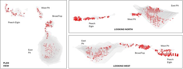
|
Figure 13-2: Copper World Variability Samples - Hardness
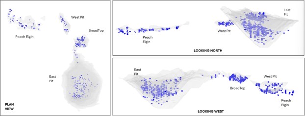
Figure 13-3: Copper World Variability Samples - Flotation
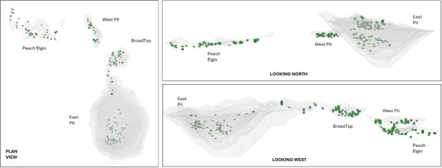
Table 13-1: Distribution of Variability Samples Tested Across Envelopes
| Sample Count | Sample Distribution | |||||
| Envelope (Interpolation Domain) | Mineralogy | Hardness | Flotation1 | Mineralogy | Hardness | Flotation |
| Outside Mineralized Envelopes | 64 | 35 | 13 | 6% | 5% | 6% |
| Footwall zone skarn | 92 | 38 | 11 | 9% | 5% | 5% |
| East Skarn | 233 | 323 | 38 | 23% | 44% | 18% |
| East oxides Low plate | 26 | 25 | 5 | 3% | 3% | 2% |
| Porphyry East | 23 | 16 | 1 | 2% | 2% | 0% |
| East oxides Up plate | 41 | 25 | 4 | 4% | 3% | 2% |
| Peach skarn | 187 | 62 | 41 | 19% | 9% | 19% |
| Porphyry Elgin | 27 | 30 | 14 | 3% | 4% | 7% |
|
| Sample Count | Sample Distribution | |||||
| Envelope (Interpolation Domain) | Mineralogy | Hardness | Flotation1 | Mineralogy | Hardness | Flotation |
| West | 91 | 48 | 40 | 9% | 7% | 19% |
| BTB skarn | 69 | 43 | 22 | 7% | 6% | 10% |
| BTB Porphyry | 157 | 82 | 23 | 16% | 11% | 11% |
| Total | 1010 | 727 | 212 | 100% | 100% | 100% |
| 1 167 samples with automated mineralogy | ||||||
13.3 Mineralogy
From a mineralogical perspective, the Copper World Project has been extensively characterized. Across the various test programs, a robust quantitative mineralogical database has been established, consisting of the following analyses:
• Automated Mineralogy by Scanning Electron Microscopy: Quantitative Evaluation of Minerals by Scanning Electron Microscopy (QEMSCAN) analysis on 107 variability samples and 7 composites, Bulk Mineral Analysis by Scanning Electron Microscopy - Energy Dispersive X-ray Spectroscopy (SEM-EDX) on 3 composite samples, and TESCAN Integrated Mineral Analyzer (TIMA-X) on 903 variability and 15 composite samples. These analyses provide a comprehensive spatial database quantifying modal mineralogy, metal deportment, mineral liberation, and locking characteristics across the deposit. The results of pertinent composite sample modal mineralogy are given in Table 13-2 to Table 13-4. TIMA-X copper deportment data are given Table 13-5.
• Cation Exchange Capacity (CEC): Analytical testing on 431 variability samples to provide a proxy for clay concentrations.
• Fourier Transform Near-Infrared Spectroscopy (FTNIR): Spectroscopic analysis on 477 variability samples for the identification of alteration minerals, silicates, and clay subtypes.
• X-ray Diffraction (XRD): Bulk mineralogy and crystalline phase identification on 915 variability samples to quantify major mineral proportions.
• Clay X-ray Diffraction (Clay XRD): Targeted clay-fraction speciation on 126 variability samples to differentiate and quantify swelling vs. non-swelling clay species and phyllosilicates.
The primary mineralogical drivers dictating metallurgical response are copper deportment, talc, swelling and non-swelling clays, and pyrite. Predictive models were developed for each of these species using the mineralogical database. Copper deportment, talc, and pyrite were modeled using the automated mineralogy database. Clay mineralization was modeled using the cation exchange capacity (CEC), Fourier transform near-infrared (FTNIR), and clay X-ray diffraction (XRD) datasets.
The predictive models for copper deportment, talc, and clay mineralization leverage Random Forest algorithms, using multi-element geochemical assays to estimate quantitative mineralogy. Random Forest is effective in isolating complex, non-linear relationships characteristic of geological datasets. The resulting machine learning models demonstrate strong predictive performance, achieving high correlation coefficients (R2) as discussed in Section 14.
|
Table 13-2: QEMSCAN Modal Abundance of East Deposit Composite Samples
| Mineral | Base 1 | Base 2 | Base 3 | Sub 4: Elevated Copper Oxide |
Sub 5a: Elevated Swelling Clay |
Sub 5b: Elevated Mg Clay |
Sub 6: Hard |
| Chalcopyrite | 0.4 | 0.9 | 1.0 | 0.3 | 0.7 | 1.0 | 0.7 |
| Bornite | 0.2 | 0.2 | 0.1 | 0.1 | 0.1 | 0.3 | 0.3 |
| Chalcocite/Covellite | 0.1 | 0.2 | 0.1 | 0.2 | 0.4 | 0.0 | 0.1 |
| 2nd Cu-Silicates-Oxides | 0.1 | 0.3 | 0.1 | 0.8 | 0.1 | 0.1 | 0.1 |
| Pyrite | 0.4 | 0.5 | 0.2 | 0.1 | 0.3 | 0.7 | 0.3 |
| Mg Clays | 2.2 | 3.4 | 6.4 | 1.3 | 2.6 | 18.7 | 0.9 |
| Mica | 0.5 | 0.9 | 1.0 | 0.8 | 3.4 | 0.5 | 2.4 |
| Chlorite | 1.7 | 2.6 | 1.8 | 2.7 | 4.0 | 3.0 | 2.0 |
| Quartz | 23.3 | 15.4 | 7.1 | 25.5 | 24.5 | 0.3 | 19.1 |
| K-Feldspar | 7.0 | 8.4 | 3.1 | 9.2 | 13.6 | 0.4 | 21.7 |
| Andradite | 24.2 | 16.5 | 14.6 | 21.7 | 8.5 | 5.8 | 11.0 |
| Calcite | 17.9 | 26.9 | 39.5 | 23.3 | 14.6 | 40.5 | 6.4 |
| Other | 22.0 | 23.8 | 25.0 | 14.0 | 27.2 | 28.7 | 35.0 |
| Total | 100.0 | 100.0 | 100.0 | 100 | 100 | 100 | 100 |
Table 13-3: Bulk Mineral Analysis by SEM-EDX Modal Abundance of East Deposit Composite Samples
| Mineral | Period 1 | Period2 | Period 3 |
| Chalcopyrite | 0.4 | 0.4 | 0.6 |
| Bornite | 0.2 | 0.3 | 0.6 |
| Chalcocite/Covellite | 0.1 | 0.1 | 0.3 |
| 2nd Cu-Silicates-Oxides | 0.0 | 0.0 | 0.1 |
| Pyrite | 0.3 | 0.3 | 0.6 |
| Mg Clays | 0.1 | 4.7 | 2.3 |
| Mica | 1.5 | 2.1 | 1.8 |
| Chlorite | 0.9 | 2.4 | 3.3 |
| Quartz | 25.0 | 12.0 | 12.0 |
| K-Feldspar | 16.0 | 18.0 | 15.0 |
| Andradite | 19.0 | 10.0 | 16.0 |
| Calcite | 7.3 | 16.0 | 16.0 |
| Other | 29.2 | 33.7 | 31.4 |
| Total | 100.0 | 100.0 | 100.0 |
Figure 13-4: TIMA Modal Abundance of Copper World Composite Samples
| Mineral | East Transitional |
RMC2 | RMC3 | East S2 |
Broad Top Transitional |
BTMC2 | Broad Top High Oxide |
Peach PEA |
Elgin PEA |
EMC2 | Peach FS |
CWMC2 | West FS |
| Chalcopyrite | 0.2 | 0.5 | 0.5 | 0.8 | 0.2 | 0.8 | 0.8 | 0.3 | 0.3 | 0.5 | 0.6 | 0.8 | 0.6 |
| Bornite | 0.1 | 0.2 | 0.1 | 0.1 | 0 | 0 | 0 | 0.1 | 0 | 0 | 0 | 0 | 0 |
| Chalcocite/Covellite | 0.2 | 0.2 | 0.3 | 0.1 | 0.2 | 0.1 | 0 | 0 | 0 | 0 | 0 | 0.3 | 0.1 |
| 2nd Cu-Silicates-Oxides | 1.5 | 0.8 | 0.5 | 0.1 | 1.4 | 0.6 | 1.2 | 1.1 | 0.4 | 0.4 | 0.8 | 0.1 | 3.4 |
|
| Mineral | East Transitional |
RMC2 | RMC3 | East S2 |
Broad Top Transitional |
BTMC2 | Broad Top High Oxide |
Peach PEA |
Elgin PEA |
EMC2 | Peach FS |
CWMC2 | West FS |
| Cu Wad | 0.5 | 0.1 | 0.1 | 0.3 | 0.4 | 0.2 | 0.5 | 0.6 | 0.2 | 0.2 | 0.2 | 0.1 | 0.1 |
| Pyrite | 0.3 | 1.1 | 0.9 | 1.1 | 0.2 | 0.6 | 0.5 | 0.3 | 0.5 | 1.8 | 0.4 | 3.4 | 1.6 |
| Talc | 0.8 | 0.4 | 1.3 | 0.9 | 1.5 | 0.7 | 0.9 | 0.8 | 1.3 | 0.2 | 1.7 | 0.3 | 3.5 |
| Mica | 1.6 | 0.4 | 0.6 | 1.2 | 4.3 | 2.1 | 1.5 | 1.5 | 2.7 | 1.4 | 1.3 | 3 | 2 |
| Chlorite | 1.5 | 0.5 | 0.7 | 1.2 | 0.9 | 0.9 | 1.4 | 1.1 | 1.1 | 1.1 | 1.1 | 0.7 | 1.6 |
| Quartz | 24.8 | 16.2 | 16 | 21 | 39 | 28.2 | 25 | 22.6 | 30.7 | 31.7 | 25.6 | 27.5 | 28.6 |
| K-Feldspar | 21 | 8.8 | 7.6 | 8.5 | 29.2 | 19.4 | 17.4 | 7.9 | 20.7 | 21.8 | 14.8 | 12.3 | 9.5 |
| Andradite | 20.2 | 31.4 | 29.5 | 23.6 | 4.9 | 17.6 | 13.4 | 33.8 | 11.4 | 10.7 | 15 | 25.1 | 19.1 |
| Calcite | 6.4 | 10 | 9.9 | 11.8 | 4.2 | 4.3 | 7.7 | 5.1 | 8.7 | 7.1 | 12 | 5.7 | 10.5 |
| Other | 20.8 | 29.3 | 32.1 | 19.3 | 13.8 | 24.5 | 29.7 | 24.6 | 22 | 23.1 | 26.5 | 20.7 | 19.4 |
| Total | 100 | 100 | 100 | 100 | 100 | 100 | 100 | 100 | 100 | 100 | 100 | 100 | 100 |
Figure 13-5: TIMA Copper Deportment in Copper World Composite Samples
| Mineral Type |
Mineral | East Transitional |
RMC2 | RMC3 | East S2 |
Broad Top Transitional |
BTMC2 | Broad Top High Oxide |
Peach PEA |
Elgin PEA |
EMC2 | Peach FS |
CWMC2 | West FS |
| Sulfide | Chalcopyrite | 20.1 | 35.6 | 32.1 | 55.4 | 19.9 | 76 | 72.8 | 41.1 | 55.2 | 60.8 | 65.4 | 49.4 | 53.8 |
| Chalcocite | 32.2 | 30.3 | 44.7 | 20.3 | 40 | 10.7 | 3.7 | 11.3 | 14.8 | 6.5 | 1.7 | 38.8 | 9.9 | |
| Bornite | 20.7 | 27 | 18.4 | 11.6 | 3.5 | 5.8 | 4.2 | 13 | 13.1 | 11.6 | 4.9 | 4.47 | 5.2 | |
| Enargite | 0 | 0 | 0 | 0.2 | 0 | 0 | 0 | 0 | 0.1 | 0 | 0.6 | 0 | 0 | |
| 2nd Cu-Silicates-Oxides | Copper Oxide (CuO) | 5 | 0 | 0.2 | 1.2 | 0.2 | 0 | 0.2 | 0.1 | 0 | 0 | 2.6 | 0 | 5.7 |
| Malachite | 0.6 | 0.9 | 0.8 | 0.7 | 2.5 | 0.5 | 1.5 | 2.2 | 2 | 11.8 | 3.6 | 0.5 | 0.2 | |
| Chrysocolla | 1.4 | 0.7 | 0.3 | 0.8 | 15.3 | 0.7 | 2.7 | 6.7 | 1.5 | 1.5 | 7.6 | 0.5 | 1.9 | |
| Chrysocolla(Cu-deficient) | 0.1 | 0 | 0 | 0.4 | 0.4 | 0.1 | 0.5 | 0.8 | 0.3 | 0.2 | 0.4 | 0 | 0.1 | |
| Cu-(high)-goethite | 1.4 | 0.6 | 0.1 | 0.2 | 2 | 0.3 | 0.2 | 2.7 | 2.2 | 0.4 | 2.2 | 0.2 | 0.3 | |
| Cu-goethite | 6.2 | 2.5 | 1.5 | 3.9 | 5.6 | 2.5 | 5.9 | 3 | 2.3 | 1.6 | 4.1 | 0.7 | 13.9 | |
| Cu-goethite(high Si) | 2.6 | 0.6 | 0.5 | 1.6 | 2.6 | 0.9 | 2.8 | 5.2 | 2.6 | 1.4 | 1.4 | 3.4 | 5.3 | |
| Wad | Pitch Copper Wad (Mn) | 2 | 0.2 | 0 | 0.6 | 0.7 | 0.2 | 0.7 | 3.9 | 1.6 | 0.6 | 1.4 | 0.3 | 1.1 |
| Cu-Mn-Chlorite | 1.4 | 0.1 | 0.1 | 0.2 | 0.3 | 0.1 | 0.3 | 0.6 | 0.3 | 0.2 | 0.2 | 0.1 | 0.1 | |
| Cu-Chlorite | 4.2 | 0.4 | 0.6 | 1.8 | 5.7 | 1.4 | 2.8 | 5.7 | 2.6 | 1.7 | 0.6 | 0.9 | 0.4 | |
| Fe-Al-Silicate-low Cu | 1.1 | 0.2 | 0.2 | 1 | 0.9 | 0.5 | 1 | 3.2 | 1.1 | 1.1 | 0.7 | 0.1 | 0.2 | |
| Other | 1.1 | 0.9 | 0.4 | 0.1 | 0.5 | 0.2 | 0.7 | 0.4 | 0.3 | 0.7 | 2.6 | 0.7 | 1.9 | |
| |
Total | 100 | 100 | 100 | 100 | 100 | 100 | 100 | 100 | 100 | 100 | 100 | 100 | 100 |
| Sulfides | 73 | 92.9 | 95.2 | 87.5 | 63.4 | 92.5 | 80.7 | 65.4 | 83.2 | 79 | 72.6 | 92.6 | 68.9 | |
| 2nd Cu-Silicates-Oxides | 17.3 | 5.3 | 3.5 | 8.8 | 28.6 | 5 | 13.8 | 20.7 | 10.9 | 16.9 | 21.9 | 5.4 | 27.4 | |
| Wad | 9.8 | 1.8 | 1.3 | 3.7 | 8.1 | 2.5 | 5.5 | 13.8 | 5.9 | 4.1 | 5.5 | 2 | 3.7 |
|
13.4 Comminution
An Ore hardness engineering baseline for circuit design and throughput forecasting relied on a comminution database that was compiled from multiple testing campaigns. This database contains the following data:
• SAG Power Index (SPI) / SAG Grindability Index (SGI): 727 variability samples.
• Bond Ball Mill Work Index (BWiBall): 727 variability samples.
• JK Drop Weight and SMC Testing: 55 variability samples.
• Bond Rod Mill Work Index (BWiRod): 37 variability samples.
• Bond Impact Crusher Work Index (CWi): 20 variability samples.
• Bond Abrasion Index (Ai): 189 variability samples.
Hardness metrics were correlated across testing methodologies and benchmarked against historical industrial datasets to ensure data integrity. This multi-index database supports downstream throughput and comminution circuit modeling using industry-standard frameworks-including Bond, Bond-Barratt, Morrell, and SGI-based approaches-to validate and de-risk the plant design. Global hardness statistics are summarized in Table 13-4.
Hardness metrics were integrated into the spatial block model using a Random Forest machine learning algorithm to predict SGI and BWiBall values from geochemical assays (see section 14)
Comminution design criteria for both the initial phase (60 kstpd) and the expansion phase (90 kstpd) were established by linking predicted hardness values with the production schedule. The final design basis was selected using the 75th percentile hardness of ore processed in the peak-hardness year. Summaries of the process design criteria and circuit-specific energy requirements across modeling approaches are provided in Table 13-5 and Table 13-6.
Table 13-4: Summary of Comminution Statistics Across all Samples Tested
| Statistic | BWiCrush | DWT / SMC Test® | SMC Test® | SGI/SPI (min) |
BWiRod (kWh/mt) |
BWiBall (kWh/mt) |
Ai (g) |
|||||
| Relative Density |
A x b | ta | DWI kWh/m3 |
Mia kWh/mt |
Mih kWh/mt |
Mic kWh/mt |
||||||
| Samples Tested | 20 | 55 | 55 | 55 | 22 | 22 | 22 | 22 | 727 | 37 | 727 | 189 |
| Average | 12.8 | 2.8 | 51 | 0.53 | 5.9 | 16.5 | 12.0 | 6.2 | 100 | 13.2 | 12.5 | 0.29 |
| Standard Deviation | 4.82 | 0.2 | 21 | 0.28 | 2.1 | 4.7 | 4.2 | 2.2 | 56 | 3.5 | 2.6 | 0.17 |
| Minimum | 7.0 | 2.5 | 133 | 1.49 | 2.2 | 7.4 | 4.4 | 2.3 | 13 | 7.2 | 5.7 | 0.00 |
| 25th Percentile | 9.6 | 2.7 | 56 | 0.62 | 4.2 | 13.5 | 9.1 | 4.7 | 63 | 11.4 | 10.8 | 0.14 |
| Median | 12.0 | 2.9 | 47 | 0.47 | 6.4 | 16.8 | 12.1 | 6.3 | 92 | 12.4 | 12.6 | 0.29 |
| 75th Percentile | 14.0 | 2.9 | 39 | 0.37 | 7.0 | 19.4 | 14.4 | 7.5 | 123 | 14.4 | 14.0 | 0.42 |
| 85th Percentile | 15.9 | 3.0 | 32 | 0.32 | 8.0 | 19.9 | 15.2 | 7.8 | 151 | 16.3 | 15.0 | 0.46 |
| Maximum | 27.4 | 3.4 | 19 | 0.14 | 10.2 | 26.5 | 21.3 | 11.0 | 401 | 24.2 | 21.7 | 0.63 |
|
Table 13-5: Comminution Design Criteria
| Hardness Parameter | Design Value | |
| Year 1 - 4 | Year 5 + | |
| SGI (min) | 110 | 144 |
| A x b | 38 | 32 |
| BWiRod (kWh/mt) | 14.8 | 16.5 |
| BWiBall (kWh/mt) | 13.6 | 14.5 |
| Dwi (kWh/m3) | 7.1 | 8.4 |
| ta | 0.40 | 0.33 |
| Mia | 20.2 | 23.1 |
| Mih | 15.3 | 18.1 |
| Mic | 7.9 | 9.4 |
| Ai | 0.34 | 0.20 |
Table 13-6: Total Circuit Specific Energy Requirements
| Method | Specific Energy Requirement (KWh/mt) | |
| Year 1 - 4 | Year 5 + | |
| Bond (Crushing-Rod-Ball) | 11.1 | 11.9 |
| Barratt-Bond | 14.3 | 15.3 |
| Morrell | 14.6 | 17.0 |
| SGI | 15.7 | 16.2 |
| 1 SAB circuits typically use ~ 25 % more specific energy than the conventional Bond crushing-rod-ball milling circuit. | ||
13.5 Flotation
A flotation protocol has been established for the various ore types at Copper World. Geometallurgical drivers affecting performance have been defined, also the primary/regrind sizes, pulp densities and flotation chemistries required to maximize flotation performance. Testwork evaluated composite samples across various pits, time periods, and geometallurgical subtypes, alongside variability testing.
The primary mineralogical drivers of flotation response in the East Pit-copper deportment, talc, and clays-remain consistent across the other Copper World deposits. However, reactive pyrite also emerges as a significant factor in these areas. Specifically, the other pits contain lower secondary copper sulfide deportment and higher concentrations of reactive pyrite, requiring additional mitigation strategies.
The following subsections detail the specific evaluation and optimization of key process parameters, including primary grind size, regrind requirements, pulp density, and reagent chemistry, developed to address these mineralogical characteristics and optimize overall circuit performance.
|
13.5.1 Primary Grind Size
A series of primary grind size (P80) sensitivity tests were conducted across key deposit composites to establish target grind criteria. As shown in Figure 13-6, copper rougher recovery across most composites is largely uninfluenced by variations in primary grind size up to 150 µm. Several test series indicate potential upside to coarsening the grind target up to 180 µm without sacrificing rougher recovery.
Transitional material displays a marked sensitivity to over-grinding. Composites such as East Transitional and Broad Top Transitional exhibit a noticeable decrease in copper recovery when ground finer than 150 µm, with performance dropping off significantly as the grind approaches 100 µm.
It is hypothesized that finer grinding may liberate less floatable non-sulfide copper minerals, increasing the proportion of copper reporting to tailings and lowering total copper recovery in the rougher stage.
The demonstrated recovery stability up to 150 µm supports its selection as the baseline primary grind target, optimizing mill throughput and reducing grinding energy requirements. Avoiding over-grinding is critical to limiting the generation of ultra-fine clays, which can impair downstream metallurgical performance.
13.5.2 Regrind Size
Evaluating sensitivity to regrind size has proven challenging due to the inherent fineness of the concentrate produced from the primary grind and rougher flotation stages. Rougher concentrate P80 sizes ranged from 20 µm to 77 µm across the test programs, exhibiting a bimodal particle size distribution where significant entrained non-sulfide gangue skews the overall concentrate sizing finer relative to the actual copper mineral size distribution (Figure 13-7).
For copper liberation, testing indicates that a regrind target P80 of 45 - 55 µm is generally adequate; however, the use of finer regrinding has demonstrated improved grade-recovery performance (Table 13-7). In certain instances, finer regrinding was associated with reduced recovery, an outcome likely caused by regrinding the entire un-cycloned rougher concentrate, which overgrinds clays and suppresses downstream cleaner flotation efficiency. In plant operations, a cyclone classification circuit ahead of the regrind mill will bypass fine material to prevent overgrinding. Based on testwork evaluations, a regrind circuit (P80) particle size target of 15 µm to 25 µm for the overall cleaner feed, yielding an effective liberated copper P80 size of 25 µm to 50 µm, has been applied to the design.
|
Figure 13-6: Primary Grind vs. Recovery Performance
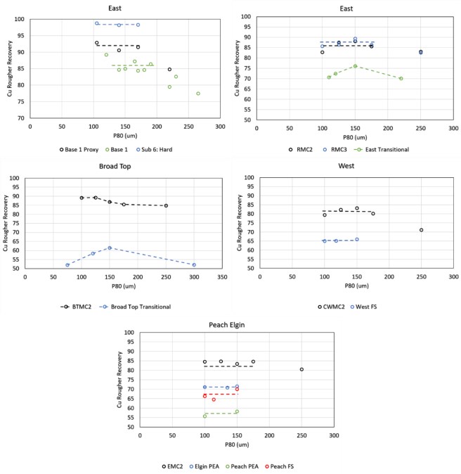
|
Figure 13-7: Primary Grind vs. Recovery Performance
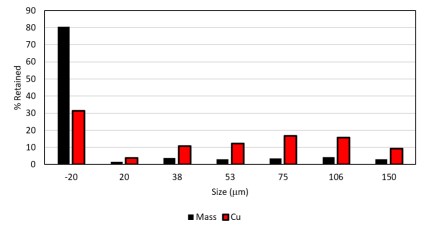
Table 13-7: Copper Grade and Recovery at Different Regrind Size for Base 1 and Base 2 Composite Samples
| Stream | Base 1 | Base 21 | ||||||||
| 47 um | 19 um | 50 um | 32 um | 16 um | ||||||
| Dist | Grade | Dist | Grade | Dist | Grade | Dist | Grade | Dist | Grade | |
| Copper Grade/Recovery | 83 | 31 | 79 | 37 | 64 | 22 | 64 | 33 | 64 | 35 |
| 1Base 2 tests at 32 um and 16 um included Sodium hexametaphosphate | ||||||||||
13.5.3 Pulp Density
Flotation performance across the Copper World ore types typically exhibits a strong sensitivity to pulp density, driven primarily by fine gangue entrainment mechanisms. While the baseline Process Design Criteria specifies a rougher feed density of 30% solids, flotation testwork demonstrates that most ore composites remain cleanable even when processed at pulp densities up to 34 % solids. The cleaner is more sensitive to feed density and should be maintained at 20% solids or below.
Across six composites, decreasing rougher pulp density from baseline levels (31% - 34% solids) down to reduced levels (25% - 27% solids) yielded a 32% to 68% reduction in total mass pull (Figure 13-8). For four of the six composites, copper recovery remained essentially flat, changing by less than ± 1% (Figure 13-8). The Base 2 composite saw a slight increase in recovery (+ 3%) at reduced density whereas for East S2 the recovery was reduced by 5%.
In the cleaning circuit reducing the pulp density to approximately 20% solids has been shown to be necessary across key composites (Figure 13-9). At higher densities, ore which is higher in clays (particularly Mg-clays) build up the recirculating load of entrained mass which results in dilution of the concentrate and losses to the cleaner tailings.
|
Figure 13-8: Mass and Copper Recovery at Baseline (31 % - 34 % solids) and Low (25 % - 27 % solids) Rougher % Solids
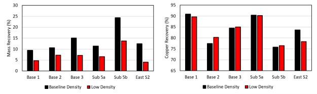
Figure 13-9: Cu Grade and Recovery at Varying Cleaner % Solids
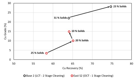
Overall, because the mass recovery across the rougher and cleaner flotation stages consists heavily of entrained fine gangue, operating at reduced pulp densities provides a critical operational lever to minimize clay transport, stabilize circulating loads and limit losses in the cleaning stage. Despite the potential metallurgical benefits of reduced slurry densities, implementing significant dilution across the rougher circuits presents substantial capital and operational trade-offs. At a nominal processing throughput of 60 kstpd, diluting the rougher feed from 30% solids down to 25% solids requires a 29% increase in recirculating process water and a 25% increase in total volumetric flow through the plant, which inherently expands equipment sizing, piping, pumping requirements, and overall cell volumes across the circuit.
To capture the benefits of entrainment reduction without incurring the volumetric and water penalties of diluting conventional mechanical cells, Jameson Cells are being installed as low-entrainment flotation devices. These pneumatic flotation cells decouple mixing from the separation volume by confining intense, high-shear contacting strictly to the downcomer. This design choice minimizes circulating loads, protects recovery, and optimizes overall flotation performance without requiring prohibitive increases in rougher circuit footprint or process water requirements.
|
13.5.4 Flotation Reagent Suite and Chemical Regime
The extensive focus on understanding ore variability and geometallurgical ore types has led to a flexible and robust chemical regime, establishing a flotation protocol capable of treating all expected ore types across the Copper World Project.
To achieve optimal copper recovery while managing challenging deleterious minerals-such as reactive pyrite, talc, and clays-a targeted reagent strategy was developed. The reagent suite comprises standard industrial collectors, frothers, depressants, dispersants, and pH modifiers, each serving a specific function depending on the mineralogical domain being processed. The detailed functions and evaluations of each reagent class are outlined in the following subsections.
13.5.4.1 Cu Collectors
Sodium isobutyl xanthate (SIBX) has been established as an effective primary copper collector across the various test programs. Several co-collectors were also evaluated, including thionocarbamates (AERO 3894, AERO 473), dithiophosphates (AERO MX-3714, AERO 208), and hydroxamates (AERO OX-100).
Testing demonstrated no meaningful difference in copper recovery among the tested co-collector variants compared to using SIBX alone. While this does not preclude further circuit optimization during operation, it indicates that, for laboratory benchmarking and economic evaluation, varying the collector suite offers limited upside. Ultimately, a thionocarbamate co-collector (AERO 3894) was retained in the baseline flowsheets, aligned with the recognized industry practice of employing co-collectors rather than a demonstrated performance increase in the testwork.
The selection of SIBX over potassium amyl xanthate (PAX) was driven by caution regarding downstream copper flotation reversibility during copper/molybdenum separation. Furthermore, SIBX provides improved selectivity over pyrite when processing ore from the other pits.
13.5.4.2 Frother
Limited frother optimization has been performed to date. Methyl isobutyl carbinol (MIBC) served as the primary frother across the test programs and demonstrated sufficient baseline performance. Detailed frother optimization is best conducted at the plant scale, as laboratory batch cells cannot fully replicate industrial cell hydrodynamics, continuous froth transport, deep-bed froth stability, and process water recycling effects.
Consistent with the approach established for collectors, a dual-frother strategy has been implemented in accordance with industry best practice. This strategy combines a volatile, weak frother with a non-volatile, stronger frother.
|
13.5.4.3 Sulphidizing Agent
Sulfidization using sodium hydrosulfide (NaHS) has demonstrated a marked improvement in flotation recovery for Copper World ores. The optimal flotation condition occurs at a sulfide ion electrode (SIE) potential between -300 mV and -400 mV. Within this range, bisulfide (HS-) acts as an activator by sulfidizing copper oxide minerals and re-sulfidizing tarnished or oxidized copper sulfide mineral surfaces, thereby enhancing their floatability. This response is demonstrated for composite samples in Figure 13-10 and for selected variability samples in Figure 13-11. However, at "SIE" potentials more negative than approximately -400 mV, excess bisulfide depresses copper minerals, underscoring the critical need for tight operational control over NaHS dosage.
Figure 13-10: Cu Recovery vs. NaHS Concentration. Each Dosage Increase Represents SIE Potentials of Nat, - 300 mV, - 400mV and -500 mV
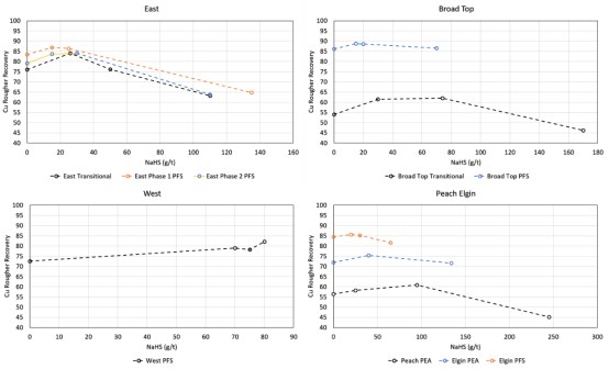
Figure 13-11: Flotation recovery with and without NaHS on selected variability samples
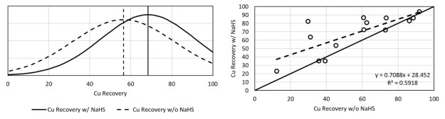
|
13.5.4.4 Molybdenum Collector
Optimization of the molybdenum collector suite has been limited to date. Diesel fuel served as the primary collector across the test programs, and its positive influence on molybdenum recovery is demonstrated across various variability samples (Figure 13-12). While diesel is retained as the baseline collector for the current study, preliminary testing on the East S2 sample indicated a substantial uplift in molybdenum recovery when switching to Molyflo® Flotation Oil (Figure 13-13). Further work is underway to quantify this performance enhancement across additional ore domains.
Figure 13-12: Mo Recovery Across Variability Samples with and Without Diesel
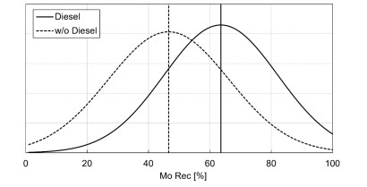
Figure 13-13: Molybdenum flotation performance from East S2 sample using diesel vs. Molyflo® Flotation Oil
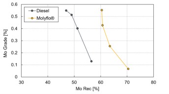
13.5.4.5 Dispersant
The use of a dispersant to improve flotation performance was first established during the 2014-2016 test work programs, where adding 300 g/t of sodium hexametaphosphate (SHMP) to the rougher circuit significantly improved Cu flotation performance, increasing recovery by up to 8 % (Figure 13-14). No additional testing was conducted to optimize the SHMP dosage.
|
A different dispersant (NS1162) was evaluated during the 2025-2026 test work. The addition of NS1162, combined with reduced pulp density in the cleaning circuit, substantially improved flotation performance (Figure 13-15). Preliminary scoping work indicates that a dosage of 50 g/t added strictly to the cleaning circuit is sufficient to achieve this benefit. Further optimization work should be conducted to establish the optimum dosage across a variety of ore types and plant conditions.
Figure 13-14: Impact of SHMP on Cu Flotation Performance in Period 2 and Period 3 Samples
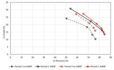
Figure 13-15: Impact of 50 g/g NS1162 on the Flotation Performance of the East S2 Sample
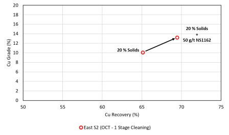
|
13.5.4.6 pH Modifier
Testwork indicates that lime addition is unnecessary to achieve saleable concentrate grades for most of the East Pit ore. For other pit ores (particularly West Pit), which contain higher pyrite concentrations and a lower distribution of Cu to secondary sulfide species, lime is utilized to elevate slurry pH for pyrite depression (Figure 13-16). Further optimization work should be conducted to confirm Lime is unnecessary across a variety of ore types and plant conditions (see 13.5.4.7).
13.5.4.7 Pyrite Depressant
Metallurgical testing demonstrates that active pyrite depression is not required for most of the ore. In contrast, pyrite present in the other pits (particularly West Pit) is highly floatable and does not always respond to depression by lime alone. The addition of sodium cyanide (NaCN) effectively depresses this reactive pyrite, significantly improving the overall copper flotation response (Figure 13-16).
Figure 13-16: Impact of Lime and Cyanide on the Depression of Pyrite in Broad Top High Oxide and West FS Samples
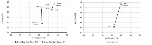
13.5.5 Flotation Protocol
The following baseline protocol and active pyrite mitigation were selected:
Baseline Protocol: 30% rougher solids, 20% cleaner solids, Natural pH, NaHS (-300 mV SIE), SIBX (25 g/t), AERO 3894 (17.5 g/t), Diesel (17.5 g/t), MIBC (15 g/t), Dowfroth 250 (10 g/t), NS1162 (50 g/t).
Active Pyrite Mitigation: Lime to pH 9.5 (rougher) / pH 11.5 (cleaner), NaCN (5 g/t).
13.5.6 Locked-Cycle Tests
A comprehensive series of locked-cycle test (LCT) and simulated LCTs from open-cycle tests (OCT) were completed across test programs and are summarized in Table 13-8 to Table 13-11. Key flotation metrics include:
|
• Copper Performance: High-grade primarily sulfide ores yielded higher performance achieving 75 % - 91 % Cu recovery at final concentrate grades of 21 % - 36 % Cu. More oxidized material showed reduced performance, with recoveries ranging from 57 % - 66 % at concentrate grades of 18 % - 26 % Cu.
• Molybdenum Deportment: Molybdenum recovery to the bulk concentrate showed significant variability across ore domains, ranging from 10 % to 84 % Mo at final concentrate grades of 0.14 % to 0.69 % Mo.
• Precious Metal Recovery: Precious metals successfully upgraded into the final concentrate, with silver recoveries between 25 % and 68 % (58ppm to 205 ppm Ag) and gold recoveries between 26 % and 64 % (0.3 ppm to 1.5 ppm Au). Tests from the 2014-2016 program do not include Ag and Au assays for all streams, but these tests produced concentrates grading 166 ppm to 509 ppm Ag and 0.8 ppm to 3.1 ppm Au.
The locked-cycle testing confirms that stable circuit operation and market-acceptable copper concentrate grades are achievable, while providing the performance benchmarks used for metallurgical recovery modeling.
Table 13-8: LCT and simulated LCT results performed by XPS as part of the 2014 - 2016 testwork program
| Sample | Test | Stream | Cu | Mo | ||
| Distribution (%) | Grade (%) | Distribution (%) | Grade (%) | |||
| Base 1 | LCT | Feed | 100 | 0.61 | 100 | 0.01 |
| Concentrate | 83 | 31.2 | 60 | 0.50 | ||
| Cleaner Tail | 6 | 0.69 | 17 | 0.04 | ||
| Rougher Tail | 12 | 0.07 | 24 | 0.00 | ||
| Base 2 | LCT | Feed | 100 | 0.59 | 100 | 0.02 |
| Concentrate | 75 | 28.2 | 45 | 0.62 | ||
| Cleaner Tail | 5 | 0.30 | 17 | 0.04 | ||
| Rougher Tail | 20 | 0.14 | 38 | 0.01 | ||
| Base 3 | OCT - Simulated LCT | Feed | 100 | 0.55 | 100 | 0.01 |
| Concentrate | 80 | 29.0 | 45 | 0.34 | ||
| Cleaner Tail | 5 | 0.32 | 13 | 0.01 | ||
| Rougher Tail | 16 | 0.10 | 43 | 0.01 | ||
| Sub 4 | LCT | Feed | 100 | 0.54 | 100 | 0.01 |
| Concentrate | 61 | 31.9 | 43 | 0.20 | ||
| Cleaner Tail | 4 | 0.75 | 6 | 0.01 | ||
| Rougher Tail | 34 | 0.19 | 51 | 0.00 | ||
| Sub 5A | LCT | Feed | 100 | 0.46 | 100 | 0.01 |
| Concentrate | 82 | 22.6 | 54 | 0.33 | ||
| Cleaner Tail | 7 | 0.44 | 23 | 0.03 | ||
| Rougher Tail | 12 | 0.06 | 23 | 0.00 | ||
|
| Sample | Test | Stream | Cu | Mo | ||
| Distribution (%) | Grade (%) | Distribution (%) | Grade (%) | |||
| Sub 5B | OCT - Simulated LCT | Feed | 100 | 0.58 | 100 | 0.02 |
| Concentrate | 68 | 20.7 | 29 | 0.26 | ||
| Cleaner Tail | 8 | 0.20 | 23 | 0.02 | ||
| Rougher Tail | 24 | 0.18 | 49 | 0.01 | ||
| Sub 6 | OCT - Simulated LCT | Feed | 100 | 0.52 | 100 | 0.02 |
| Concentrate | 90 | 28.0 | 75 | 0.69 | ||
| Cleaner Tail | 2 | 1.82 | 7 | 0.09 | ||
| Rougher Tail | 8 | 0.04 | 18 | 0.00 | ||
Table 13-9: LCT Results Performed by BML as part of the 2014 - 2016 Testwork Program
| Sample | Test | Stream | Cu | Mo | ||
| Distribution (%) | Grade (%) | Distribution (%) | Grade (%) | |||
| Period 1 | LCT | Feed | 100 | 0.54 | 100 | 0.01 |
| Concentrate | 91 | 30.4 | 84 | 0.59 | ||
| Cleaner Tail | 3 | 0.35 | 4 | 0.01 | ||
| Rougher Tail | 6 | 0.04 | 13 | 0.00 | ||
| Period 2 | LCT | Feed | 100 | 0.49 | 100 | 0.01 |
| Concentrate | 75 | 33.4 | 50 | 0.49 | ||
| Cleaner Tail | 9 | 1.15 | 10 | 0.03 | ||
| Rougher Tail | 16 | 0.08 | 40 | 0.01 | ||
| Period 3 | LCT | Feed | 100 | 0.74 | 100 | 0.02 |
| Concentrate | 76 | 36.4 | 54 | 0.65 | ||
| Cleaner Tail | 6 | 1.22 | 5 | 0.03 | ||
| Rougher Tail | 18 | 0.14 | 41 | 0.01 | ||
Table 13-10: LCT results performed by Aminpro as part of the 2022 - 2023 Testwork Program
| Sample | Test | Stream | Cu | Mo | Ag | Au | ||||
| Distribution (%) |
Grade (%) |
Distribution (%) |
Grade (%) |
Distribution (%) |
Grade (g/mt) |
Distribution (%) |
Grade (g/mt) |
|||
| RMC2 | LCT | Feed | 100 | 0.51 | 100 | 0.01 | 100 | 5.51 | 100 | 0.03 |
| Concentrate | 77 | 24.2 | 26 | 0.15 | 68 | 205 | 58 | 1.17 | ||
| Cleaner Tail | 9 | 0.30 | 22 | 0.01 | 16 | 4.74 | 12 | 0.03 | ||
| Rougher Tail | 14 | 0.08 | 52 | 0.01 | 16 | 1.66 | 30 | 0.01 | ||
| RMC3 | LCT | Feed | 100 | 0.43 | 100 | 0.02 | 100 | 5.99 | 100 | 0.03 |
| Concentrate | 81 | 24.1 | 27 | 0.39 | 43 | 194 | 62 | 1.11 | ||
| Cleaner Tail | 7 | 0.19 | 20 | 0.02 | 3 | 4.43 | 12 | 0.02 | ||
| Rougher Tail | 12 | 0.06 | 53 | 0.01 | 54 | 2.90 | 25 | 0.01 | ||
| BTMC2 | LCT | Feed | 100 | 0.35 | 100 | 0.02 | 100 | 2.31 | 100 | 0.02 |
| Concentrate | 76 | 23.1 | 44 | 0.54 | 60 | 122 | 26 | 0.38 | ||
| Cleaner Tail | 14 | 0.29 | 30 | 0.03 | 24 | 2.91 | 29 | 0.03 | ||
| Rougher Tail | 10 | 0.05 | 26 | 0.01 | 17 | < 1.00 | 45 | 0.01 | ||
|
| Sample | Test | Stream | Cu | Mo | Ag | Au | ||||
| Distribution (%) |
Grade (%) |
Distribution (%) |
Grade (%) |
Distribution (%) |
Grade (g/mt) |
Distribution (%) |
Grade (g/mt) |
|||
| CWMC2 | LCT | Feed | 100 | 0.42 | 100 | 0.02 | 100 | 2.15 | 100 | 0.02 |
| Concentrate | 66 | 19.6 | 10 | 0.14 | 25 | 66.8 | 42 | 0.28 | ||
| Cleaner Tail | 13 | 0.30 | 40 | 0.04 | 16 | 2.90 | 34 | 0.02 | ||
| Rougher Tail | 21 | 0.10 | 50 | 0.01 | 59 | 0.85 | 24 | 0.01 | ||
| EMC2 | LCT | Feed | 100 | 0.32 | 100 | 0.02 | 100 | 1.58 | 100 | 0.01 |
| Concentrate | 76 | 15.1 | 53 | 0.51 | 52 | 58.2 | 56 | 0.39 | ||
| Cleaner Tail | 12 | 0.18 | 22 | 0.02 | 19 | 1.38 | 20 | 0.01 | ||
| Rougher Tail | 12 | 0.05 | 25 | 0.01 | 28 | < 1.00 | 24 | 0.01 | ||
Table 13-11: LCT results performed by BML as part of the 2025 - 2026 testwork program
| Sample | Test | Stream | Cu | Mo | Ag | Au | ||||
| Distribution (%) |
Grade (%) |
Distribution (%) |
Grade (%) |
Distribution (%) |
Grade (g/mt) |
Distribution (%) |
Grade (g/mt) |
|||
| East FS | LCT | Feed | 100 | 0.51 | 100 | 0.01 | 100 | 3.00 | 100 | 0.04 |
| Concentrate | 75 | 23.2 | 50 | 0.43 | 64 | 127 | 64 | 1.52 | ||
| Cleaner Tail | 7 | 0.54 | 7 | 0.01 | 15 | 7.00 | 13 | 0.08 | ||
| Rougher Tail | 19 | 0.10 | 44 | 0.01 | 21 | 0.80 | 23 | 0.01 | ||
| Broad Top High Oxide | LCT | Feed | 100 | 0.35 | 100 | 0.01 | 100 | 2.00 | 100 | 0.02 |
| Concentrate | 63 | 26.1 | 26 | 0.35 | 66 | 184 | 33 | 0.86 | ||
| Cleaner Tail | 11 | 0.35 | 36 | 0.04 | 18 | 4.00 | 17 | 0.04 | ||
| Rougher Tail | 27 | 0.11 | 38 | 0.00 | 17 | 0.50 | 50 | 0.01 | ||
| West FS | LCT | Feed | 100 | 0.34 | 100 | 0.01 | 100 | 2.00 | 100 | 0.02 |
| Concentrate | 60 | 20.6 | 28 | 0.34 | 49 | 121 | 26 | 0.58 | ||
| Cleaner Tail | 6 | 0.33 | 16 | 0.03 | 10 | 4.00 | 11 | 0.04 | ||
| Rougher Tail | 34 | 0.12 | 56 | 0.01 | 41 | 1.00 | 63 | 0.01 | ||
| Peach FS | LCT | Feed | 100 | 0.31 | 100 | 0.01 | 100 | 3.00 | 100 | 0.03 |
| Concentrate | 57 | 18.8 | 72 | 0.67 | 55 | 160.0 | 49 | 1.35 | ||
| Cleaner Tail | 13 | 0.40 | 11 | 0.01 | 18 | 5.00 | 16 | 0.04 | ||
| Rougher Tail | 30 | 0.10 | 17 | 0.00 | 27 | 0.80 | 35 | 0.01 | ||
13.5.7 Variability Kinetic Flotation Tests
An extensive database of rougher flotation variability testwork has been established, comprising 212 samples (including 167 samples with TIMA mineralogical analysis) across the Copper World Project. The results highlight the strong recovery relationship to copper species deportment, as well as the detrimental impact of talc on flotation performance when present above critical feed concentrations. These findings are detailed further in Section 13.5.10. All tests followed the Simple Kinetics Test (SKT) methodology, with metallurgical results interpreted using phenomenological models.
|
13.5.8 Copper-Molybdenum Separation
Detailed copper-molybdenum (Cu/Mo) separation testwork has been limited across the Copper World programs due to the requirement to generate substantial quantities of fresh bulk Cu/Mo concentrate while avoiding sample oxidation, which can significantly alter reagent response and impair flotation performance. Molybdenum flotation evaluations to date have been performed primarily on a combined concentrate from Base 1, Base 3, Sub 4, and Sub 5a ores and a combined concentrate produced from an equal weighting of Period 1, 2, and 3 ores.
In testwork on the combined concentrate from Base 1, Base 3, Sub 4, and Sub 5a ores, an industry-standard reagent scheme incorporating lime to elevate pulp pH (10 - 12) and sodium hydrosulfide (NaHS) for oxidation-reduction potential control (-450 mV to -550 mV vs. Ag/AgCl) achieved depression of all copper sulfide species. This evaluation successfully upgraded a 0.35 % Mo bulk feed to a first cleaner concentrate grading 38% Mo, while suppressing copper reporting to the molybdenum product to 3.5 % Cu. Subsequent testing on the combined Period 1 to 3 concentrates further confirmed effective copper depression, yielding molybdenum third cleaner concentrates grading 15% to 21.5% Mo with low copper contents (1.7 % - 4.0 % Cu).
While these initial results demonstrate clear proof-of-concept for Cu/Mo separability, the variable presence of naturally hydrophobic gangue minerals, such as talc, in certain ore domains presents an operational risk to consistent production of a commercial-grade (> 50% Mo) concentrate. Additional testing, supported by geometallurgical domain mapping, should be performed to better understand these constraints.
13.5.9 Concentrate Quality
Consolidation of metallurgical data across the test programs demonstrates that the Copper World deposits produce a clean, marketable copper concentrate. Over the mine plan, projected annual concentrate grades average approximately 24% Cu, and 25% over the first 12 years of operation. Final concentrate copper grades produced in LCTs suggest Cu concentrate grades greater than 20% are achievable, with the ability to further clean the concentrate up to greater than 30% Cu. Payable precious metals upgrade significantly, with silver and gold achieving concentrate values of up to 509 ppm Ag and 3.1 ppm Au, respectively. Minor element ICP scans indicate that standard penalty elements-including lead (0.06 % - 0.40% Pb), zinc (0.26% - 3.65% Zn), arsenic (42 - 1,202 ppm As), and bismuth (27 - 446 ppm Bi)-generally remain below typical smelter penalty limits, though localized ore and concentrate blending protocols should be maintained to avoid spot excursions.
Mercury (Hg) upgrades from head grades of 0.03 - 0.08 ppm to concentrate levels of 1 - 18 ppm. Projected annual averages (4 - 8 ppm Hg) remain below smelter penalty thresholds.
Fluorine (F) has been identified as the primary deleterious element requiring active process management, with tests yielding final concentrate grades ranging from 240 to 1,340 ppm. To avoid smelter penalties or marketability constraints, controlling fluorine transport to the concentrate is critical. The blending of Fluorine bearing clay feeds to the plant will need to be managed continuously during operation. Also, rejecting Fluorine bearing talc in the cleaner circuit, and occasionally mixing and blending down final concentrate Fluorine during operation may be required.
|
Mineralogical assessments (QEMSCAN/TIMA) and liberation evaluations suggest that physical interlocking between primary fluorine-bearing minerals-specifically micas (biotite and muscovite), fluorite, and apatite-and floatable species is low, with only 10 - 20% of fluorine-bearing minerals associated with sulfides or talc (Table 13-12). These minerals report to the final concentrate almost exclusively via mechanical entrainment. The testwork demonstrates that fluorine is cleanable from the concentrate and correlated to concentrate grade, highlighting the need to control mechanical entrainment and reinforcing the selection of low-entrainment flotation technology (Jameson Cells).
Current fluorine deportment calculations rely on textbook chemical stoichiometry for recognized fluorine-bearing minerals. However, these minerals can have variable fluorine concentrations, and other minerals that are more difficult to reject, such as talc, can substitute variable fluorine into their lattice structures. Detailed fluorine deportment analysis incorporating electron microprobe analysis (EPMA) is currently underway to quantitatively map exact mineral fluorine concentrations.
Table 13-12: Fluorine Mineral Associations
| Mineral Status | Broad Top High Oxide | West FS | Peach FS | East S2 |
| Liberated F Min | 45 | 30 | 16 | 19 |
| F Min:CuS | 7 | 6 | 14 | 9 |
| F Min:Mo | 0 | 0 | 1 | 0 |
| F Min:Py | 1 | 1 | 4 | 0 |
| F Min:Oth Sul | 0 | 0 | 0 | 0 |
| F Min:Talc | 1 | 2 | 1 | 5 |
| F Min:NSG | 23 | 24 | 21 | 22 |
| Multiphase | 23 | 37 | 44 | 45 |
13.5.10 Flotation Recovery Estimates
13.5.10.1 Copper
Predictive copper recovery models have been developed from variability kinetic and LCT data to define independent mineralogical drivers affecting each flotation stage. Predictive rougher and cleaner recovery models were both developed using no-intercept ordinary least squares (OLS) regression. The rougher dataset comprised 183 kinetic flotation tests conducted on composite (n = 16) and single-interval variability (n=167) samples spatially distributed across the Copper World Project. Given the critical role of copper speciation as a primary driver of recovery, mineralogical copper deportment data were utilized as the primary predictors.
To capture its deleterious impact on rougher recovery, talc content was incorporated into a split prediction model based on a 4% concentration threshold:
• Below 4% talc: Talc is omitted from the mathematical equation as its impact is negligible.
|
• At or above 4% talc: Talc is included to account for its statistically significant detrimental effects (p ≤ 0.05).
Predictive cleaner recovery models were similarly built on mineralogical data, incorporating copper deportment alongside pyrite and talc using a dataset of 16 LCTs and 3 simulated LCTs derived from OCT flotation data. The resulting equations are:
• Below 4% talc, rougher recovery is calculated by Eq. 13.2:

• At or above 4% talc, rougher recovery is calculated by Eq 13.3:

• Cleaner recovery is calculated by Eq 13.4:

• Global recovery is calculated by Eq 13.5:

Both the rougher and cleaner models followed an identical three-phase development workflow: data input selection, model optimization, and uncertainty quantification. All modelling was executed in Python using the statsmodels library and cross-verified in Minitab® Statistical Software, with baseline features filtered by a strict p-value threshold of 0.005. While the rougher model strictly adhered to this statistical cutoff (achieving an R2 value of 0.87), the cleaner model deliberately retained talc as a forced variable (p-value = 0.295). Performance uncertainty was quantified using confidence intervals (99 % CI for rougher, 95 % CI for cleaner) and 95% prediction intervals (PI) for both stages. The resulting cleaner recovery model achieves an R2 value of 0.72.
While composite samples were used in the development of both flotation models, the two were developed independently. To validate combined model performance, actual global recoveries from the LCTs and simulated LCTs were plotted against total predicted recovery-calculated as the modelled rougher recovery multiplied by the modeled cleaner recovery. The combined model is robust, achieving an R2 value of 0.80. Regression plots displaying predicted versus measured test results for the rougher, cleaner, and combined global models are provided in Figure 13-17.
The predicted mineralogy detailed in Section 13.3 allows for integration into the block model. To ensure confidence in this approach, the rougher recovery models were run using the predicted Random Forest mineralogy and correlate strongly to both the actual test recovery values (R2 = 0.77) and the modelled recovery values derived from measured TIMA mineralogy (R2 = 0.84) (Figure 13-18).
|
Figure 13-17: Measured Cu Test Recovery vs Recoveries Predicted from OLS Regression
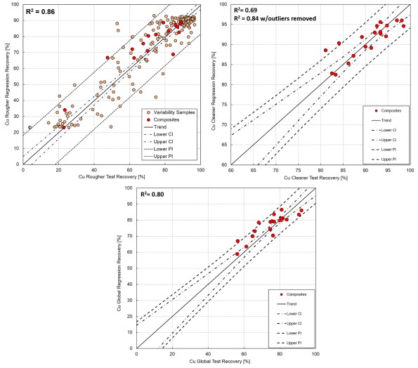
The Copper World concentrate produced in the laboratory contains both Sulfide Cu bearing minerals and non-Sulfide Cu bearing minerals. Non-Sulfide minerals represent about 20% of the concentrate and are shown to include Carbonates, Silicate, WAD, Goethite, and Oxides to varying degrees. Those same non-Sulfide minerals also represent a considerable amount of the Cu losses to tails. Optimal plant conditions will allow for total copper recovery from all mineral species bearing Cu to be optimized at an ideal Concentrate grade.
|
Figure 13-18: Predicted Rougher Cu Recovery via Random Forest Mineralogy vs. Actual Measured Recovery (R2 = 0.77) and Regression Recovery from Measured TIMA Mineralogy (R2 = 0.84)
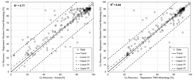
Although Cu losses may be experienced in the plant optimization process based on some mineralogies (Cu Sulfides for example), concentrate grade optimization and balancing total Cu mineral recovery in the plant may result in improved Cu recovery and economic benefits. Multiple opportunities have been identified to improve the performance of the plant relative to the lab test work. These items were identified as opportunities following the lab test work to date or identified as the effects are not reproducible in the lab and scalable to the plant. Those items include but are not limited to: frother type, addition location and consumption, Diesel reagent, NaHS dosage, Dispersant, Grind Size feeding the Jameson Cells, Thermo Scientific AnStat Stations, Belt Feed Composition Analyzers, Flotation Froth and In-Pulp Hydrodynamic Sensors, AI Applications, Online Particle Size Distribution (PSD) Sensors, Optimized Grinding Media.
The extent of improvement will not be fully known until it is actioned once the plant is in operation. Given the magnitude of opportunity to affect the total copper recovery in the plant on all mineralogy types, a 2% improvement in global copper recovery over the values calculated using the formulae developed based on laboratory test work to date was deemed reasonable and applied globally to the mill feed starting at the end of the second year of plant operation.
In addition, a ramp-up curve following industry standards was also applied to the recovery formula during the first year of operation resulting in an overall reduction of 16% in recovery during this period.
13.5.10.2 Molybdenum, Gold and Silver Recovery
Unlike copper, where mineralogical copper deportment data heavily drives the recovery model, molybdenum, gold, and silver lack the chemical or mineralogical predictors required for a similarly detailed level of recovery modeling. More detailed deportment and liberation studies for these metals could provide deeper insight into their metallurgical response.
|
Locked-cycle tests (LCTs) and simulated LCTs were used to develop a non-linear regression model for molybdenum recovery, with a factor of 90 % applied to account for the copper-molybdenum separation stage (Eq. 13.6). Regression plots displaying predicted versus measured test results are presented in Figure 13-19.
No robust recovery models could be established for gold and silver. Therefore, fixed "pit" recoveries were assigned; those recoveries are summarized in Table 13-13 along with the standard deviation of the LCT recovery data grouped by pit.

Figure 13-19: Modelled Global Mo Recovery vs Test Global Mo Recovery Plot
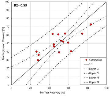
Table 13-13: Au and Ag Recovery
| Pit | Recovery (%) | |||
| Ag | Standard Deviation | Au | Standard Deviation | |
| East | 56 | 10 | 63 | 6 |
| Broad Top | 63 | 4 | 30 | 5 |
| West | 38 | 17 | 35 | 13 |
| Peach-Elgin | 52 | 6 | 58 | 7 |
|
13.6 Concentrate Dewatering
Concentrate dewatering process design criteria have been established through benchmarking against comparable copper projects. Unit area thickening and filtration rates are assumed as 0.03 st/ft2/hr and 0.04 st/ft2/hr, respectively. Copper World concentrates are currently undergoing testwork to validate these assumptions.
13.7 Tailings Dewatering and Management
Tailings management for the Copper World Project is structured around a two-phase operational strategy that transitions from solely conventional hydraulic disposal to include unsaturated dry stack management over the mine life. To support and validate this dual-phase design, an extensive series of laboratory, bench-top, and semi-pilot testwork campaigns were conducted across whole tailings, classified sands, and fine slimes fractions. Semi-pilot hydrocyclone testwork, using industrial-scale Cavex-DE re-cyclones, was executed to evaluate classification performance and establish design parameters for sand embankment construction and slimes separation.
13.7.1 Physical, Chemical and Mineralogical Characterization
Physical and chemical characterization has established baseline properties for whole tailings and classified streams. Whole flotation tailings tested exhibit P80 particle sizes between 94 µm and 195 µm, typically between 100 µm and 150 µm. Hydrocyclone overflow slimes display P80 sizes ranging from 38 µm to 96 µm. Solids specific gravity ranges from 2.7 to 3.0 for whole tailings and 2.7 to 2.9 for slimes. Conductivity values ranging between 0.76 mS/cm and 2.28 mS/cm for whole tailings and 1.23 and 2.19 mS/cm for slimes. Whole tailings show low clay activity, with Methylene Blue Index (MBI) values of 2.8 to 6.7 meq/100g. The fine slimes fraction exhibits slightly higher MBI values ranging from 4.2 to 8.4 meq/100g, reflecting localized clay concentration in the fine stream.
13.7.2 Sand Slime Splitting
Hydrocyclone classification testwork, using double-classification Cavex-DE re-cyclones, was carried out to strictly limit the fines content in the underflow sand to a maximum threshold of 15% passing 75 µm. Under nominal conditions, underflow sand mass splits ranged from 23% to 56%. To ensure adequate sand recovery for dam embankment construction, samples that generated less than 30% sand under the primary specification were rerun with a relaxed underflow target of 20% passing 75 µm, successfully increasing sand mass generation to greater than 30%.
13.7.3 Dynamic Thickening
Ixofloc AP2024 (Pochteca), a dry powder anionic polyacrylamide, was selected as the optimal flocculant due to its ability to achieve high settling rates while maintaining low supernatant clarity (< 150 - 200 NTU). Whole tailings thickened readily, achieving target underflow densities of 65% solids by weight at solids flux rates of 0.49 t/h/m² to 0.58 t/h/m² with flocculant dosages of 15 g/t to 30 g/t.
Due to the concentration of ultra-fine particles (< 20 µm), hydrocyclone overflow slimes required higher reagent additions (45 g/t to 75 g/t) at 10% to 15% feed dilution to coagulate naturally and settle. Slimes dynamic thickening achieved target underflow densities of 55% to 59% solids at flux rates of 0.28 t/h/m² to 0.32 t/h/m².
|
13.7.4 Rheology
Rheological evaluations across unsheared and fully sheared conditions indicate non-Newtonian, shear-thinning behavior:
• Whole Tailings: At the target underflow density of 65% solids, unsheared whole tailings generate yield stresses ranging from 90 Pa to 268 Pa. Upon full shearing, yield stress drops significantly to between 3 Pa and 30 Pa.
• Slimes Tailings: At the target underflow density of 55% solids, unsheared slimes exhibit yield stresses ranging from 60 Pa to 290 Pa due to the fine particle network and higher reagent dosage. Once fully sheared, yield stress decreases to between 5 Pa and 30 Pa.
• Coarse Sand Tailings: Hydrocyclone underflow sand slurries (64% to 76% solids) exhibit sheared yield stresses of 7 Pa to 105 Pa and viscosities of 0.03 Pa·s to 0.37 Pa·s.
13.7.5 Filtration Testing
Filtration testwork was conducted to evaluate dewatering performance for whole tailings dry stacking, as well as to assess the split sand and slimes streams. Trials evaluated both recessed plate/membrane pressure filtration and horizontal belt vacuum filtration through vendor testing (Tenova, FLSmidth) and independent validation by Vietti Slurrytec (VST).
Tenova's testing results were generally comparable to VST's independent sizing. VST tested a broader range of samples due to lower sample mass requirements, providing wider coverage. When comparing directly overlapping samples, VST consistently reported higher filtration rates, which may reflect their greater flexibility in operating parameters and their ability to trial alternative cloth/reagent selections from other vendors. The filtration rates across different samples measured by both VST and Tenova are:
• Integral Tailings: VST averaged 304 kg/m²/h for pressure and 452 kg/m²/h for vacuum, versus 222 kg/m²/h and 208 kg/m²/h from Tenova.
• Coarse Sand: VST averaged 249 kg/m²/h for pressure and 1,581 kg/m²/h for vacuum, versus 182 kg/m²/h and 1,167 kg/m²/h from Tenova.
• Slimes: VST averaged 186 kg/m²/h for pressure and 198 kg/m²/h for vacuum, versus 114 kg/m²/h and 70 kg/m²/h from Tenova.
Overall, pressure filtration is the recommended dewatering technology for dry stacking. Pressure filtration of whole tailings produced robust 50 mm cakes, flux rates of 113.8 kg/m²/h to 584 kg/m²/h, target cake moistures of 12.5% to 16.9%, and clear filtrate (< 150 NTU). Split sand and slimes streams also achieved favorable moistures (13.5% to 19%).
Conversely, horizontal belt vacuum filtration failed dry-stack criteria. Vacuum filtration produced thin cakes (5.5 mm to 10 mm for whole tailings; 7 mm to 17 mm for slimes), lower flux rates (55 to 380 kg/m²/h for whole tailings), high cake moisture (up to 20 % for whole tailings), and turbid filtrate (>1,000 NTU). These results indicate excessive equipment requirements, making vacuum filtration impractical.
|
13.7.6 Water Liberation
Water release and settlement characteristics vary by stream particle size:
• Whole Tailings: Water liberation occurs rapidly within 1 to 6 days, reaching initial drained dry densities of 1.3 t/m³ to 1.5 t/m³ and saturated permeabilities of 3 x 10⁻⁷ m/s to 2 x 10⁻⁶ m/s.
• Slimes Tailings: Water release completes within 1 to 14 days, achieving initial drained dry densities of 1.1 t/m³ to 1.5 t/m³ and permeabilities ranging from 3 x 10⁻⁸ m/s to 2 x 10⁻⁶ m/s. Drained in-situ dry densities are projected to increase an additional 5% to 20% over time through surface evaporation, desiccation, and consolidation.
13.7.7 Variability Testing
A comprehensive variability testing program was conducted on 125 individual samples to evaluate the sensitivity of process dewatering across different spatial and mineralogical domains of the deposit. Testing on the variability suite focused on physical sample characterization, static settling rates, self-weight consolidation, and supernatant water clarity.
Variability samples exhibited rapid settling response, yielding high static settling unit flux rates (1.0 to 1.6 t/h/m²) and achieving an average self-weight consolidation density of approximately 70% solids after 24 hours. Comparative evaluations against similar copper deposits indicate that the Copper World Project variability demonstrates superior overall consistency in settling rates and overflow water clarity.
While Ixofloc AP2024 proved to be an effective general-purpose anionic flocculant across the deposit, variable supernatant water clarity-ranging from clear to high turbidity where the settling interface was obscured-indicates that operational reagent optimization will be required over the life of mine. A minor subset of samples exhibited colloidal settling behavior capable of impacting full-scale thickener overflow clarity. To mitigate potential dynamic thickening operational upsets, mine planning strategies will incorporate ore blending to minimize the feed concentration of high-clay domains, particularly those containing swelling clays.
Because the variability program evaluated integral tailings conditions, operational design accounts for the expectation that fine slimes thickening will yield lower settling velocities, lower underflow densities, and reduced unit capacities relative to integral tailings. Overall, the variability program confirmed broad settling responsiveness across the deposit with no fatal flaws identified.
 |
14 MINERAL RESOURCE ESTIMATES
Hudbay prepared a resource model using Leapfrog® version 2022.1 and MineSight® version 15.80-07, two industry-standard, commercial geological and mining software packages. The construction of this 3D resource model and the estimation of mineral resources were performed by Hudbay personnel following Hudbay procedures in compliance with best industry standards and the CIM guidelines (CIM, 2019). The work was conducted under the supervision of Mr. Olivier Tavchandjian, P. Geo., Senior Vice President, Exploration and Technical Services, at Hudbay, Qualified Person, and author of the present report.
As described in section 10 of this Technical Report, while some limited condemnation, hydrogeological (point of compliance), geotechnical and infill drilling has been conducted by Hudbay since late 2024, this drilling was aimed at operational readiness and was not deemed to bring any material change to the resource model completed for the 2023 PFS. As a result, the same model was used as a basis for the present Definitive Feasibility Study while being also enhanced to interpolate all the elements required to develop a new geometallurgical model.
This section provides a recap of the construction of the 2023 resource model as well as describing the addition of the geochemical elements used for the prediction of hardness metrics and of copper deportment for seven groups of minerals, the abundance of total clays and swelling clays as well a predictor of the talc content in concentrate using a combination of machine learning (random forest) algorithms. A stoichiometric formula was also used to estimate the pyrite concentration based on the estimated sulfur and copper, zinc and lead sulfide bearing minerals.
14.1 Drilling Database used for the Construction of the Resource Model
1,754 drill holes totaling approximately 1,165,914 feet (355,371 m) were drilled on the Copper World property between the mid 1950's and 2023. These drillholes were imported in Leapfrog® and MineSight® from .csv files with a cut-off date for mineral resource estimate purposes of March 1st, 2023. Table 14-1 presents the drillhole breakdown by company and drilling type.
Table 14-1: Drill Hole Summary for the Copper World Property
| Churn | Rotary | RC | DDH | All DH Types | |||||||||||||
| Company | Time Period | Holes | (m) | (ft) | Holes | (m) | (ft) | Holes | (m) | (ft) | Holes | (m) | (ft) | Holes | (m) | (ft) | |
| Lewisohn | 1956 | 1957 | 28 | 3,042 | 9,980 | - | - | - | - | - | - | 18 | 2,249 | 7,377 | 46 | 5,290 | 17,357 |
| Banner | 1961 | 1963 | - | - | - | - | - | - | - | - | - | 34 | 3,828 | 12,560 | 34 | 3,828 | 12,560 |
| Anaconda | 1961 | 1972 | - | - | - | - | - | - | - | - | - | 210 | 54,376 | 178,399 | 210 | 54,376 | 178,399 |
| Anamax | 1970 | 1983 | - | - | - | 29 | 1,821 | 5,974 | - | - | - | 186 | 39,008 | 127,979 | 215 | 40,829 | 133,953 |
| Asarco | 1988 | 1992 | - | - | - | 1 | 426 | 1,399 | - | - | - | 11 | 4,479 | 14,695 | 12 | 4,905 | 16,094 |
| Augusta | 2005 | 2012 | - | - | - | 34 | 10,002 | 32,815 | - | - | - | 87 | 40,381 | 132,483 | 121 | 50,383 | 165,298 |
| Hudbay | 2014 | 2022 | - | - | - | - | - | - | 146 | 21,687 | 71,150 | 970 | 174,072 | 571,103 | 1,116 | 195,759 | 642,253 |
| Summary | 28 | 3,042 | 9,980 | 64 | 12,249 | 40,188 | 146 | 21,687 | 71,150 | 1,516 | 318,393 | 1,044,596 | 1,754 | 355,371 | 1,165,914 | ||
From these drillholes, 1,277 holes have intersected copper mineralization and were used to define the Copper World deposits along with the East Deposit. Table 14-2 presents the drillholes breakdown by deposits.
|
Table 14-2: Drill Hole Summary Per Deposit
| Deposit | Holes | Length in m within mineralized zones |
Length in ft within mineralized zones |
| East | 475 | 101,076 | 331,613 |
| Peach-Elgin | 460 | 28,624 | 93,911 |
| West | 138 | 11,632 | 38,164 |
| Broadtop Butte | 204 | 29,311 | 96,165 |
| Summary | 1,277 | 170,643 | 559,853 |
From a total drilled length of 170,643m (559,853ft) in these 1,277 holes, approximately 92-95% were analyzed for copper (Cu), iron (Fe), zinc (Zn), sodium (Na), potassium (K), magnesium (Mg), calcium (Ca), manganese (Mn), aluminum (Al), lead (Pb), sulfur (S), phosphorus (P), and arsenic (As), 67% for soluble copper (CuSS), 85% for molybdenum (Mo), 80% for silver (Ag), and 54% for gold (Au)while density (specific gravity) was measured in laboratory in 1,805 samples. In addition, core box weight was systematically collected from Hudbay drilling campaigns and constitutes the main source of data for density estimation at the Copper World deposits.
14.2 Modelling of the Mineralized Envelopes
The lithogeochemical classification and 3D interpretation described in Section 7 was used as the basis to construct smooth and continuous 3D solids of the mineralized domains in Leapfrog using also a 0.1% copper cut-off as a natural marker and general guide. (Figure 14-1).
The shallow and closely spaced drilling conducted by Hudbay over the Copper World deposits since the publication of the 2022 Preliminary Economic Assessment (PEA) has confirmed the previous spatial distribution of the key metals of economic interest and geochemical elements associated to the various alteration and mineralization processes that would influence copper deportment as well as clay and talc distribution. The only difference since the 2022 PEA was to group the footwall zones from the East and Bolsa deposits (Envelope 5 in Table 14-3).
Table 14-3 presents the envelope code equivalency that will be referred to through the remaining part of this section.
Table 14-3: Mineralized Envelopes Code Equivalency
| East Deposit | ENVLP=5 | Footwall zone - skarn |
| ENVLP=6 | Lower plate - skarn | |
| ENVLP=7 | Lower plate - skarn, middle oxide zone | |
| ENVLP=8 | Lower plate - skarn, bottom oxide zone | |
| ENVLP=10 | QMP - porphyry | |
| ENVLP=11 | Upper plate - skarn, oxide zone | |
| Other Deposits | ENVLP=12 | Peach-Elgin - skarn |
| ENVLP=13 | Peach-Elgin - porphyry | |
| ENVLP=14 | West - porphyry | |
| ENVLP=15 | Broadtop Butte - skarn | |
| ENVLP=16 | Broadtop Butte - porphyry |
|
Figure 14-1: General View of the Copper World 0.1% Grade Shells
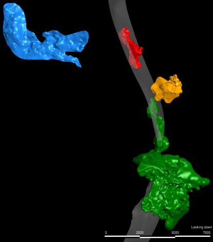
Note: East in green, Peach-Elgin in blue, West in red, Broadtop Butte in orange, and the Backbone fault in gray.
Figure 14-1 presents a general view of the 0.1% Cu grade shells for the four deposits while Figure 14-2 to Figure 14-6 present more detailed views of the envelopes used as hard boundaries for grade interpolation purposes for each deposit. These four deposits are from the Northwest to the Southeast:
• Peach-Elgin deposit hosting both skarn and porphyry mineralization
• West deposit hosting skarn mineralization located in the hanging wall of the Backbone fault.
• Broadtop Butte hosting mineralization in both porphyry and skarn mineralization
• East Deposit hosting skarn porphyry mineralization
|
Figure 14-2: Cross Section of the Mineralized Domains at East Deposit
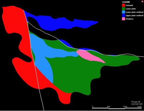
Note: Backbone fault trace = steeply dipping white line and Low Angle fault = shallow dipping white line.
Figure 14-3: Peach-Elgin Mineralized Envelopes
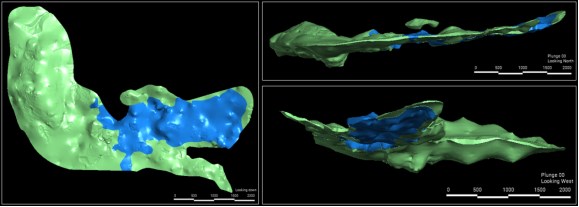
Note: Peach-Elgin skarn mineralization in green (mix of sulfide and oxides) and porphyry mineralization in blue.
|
Figure 14-4: West Mineralized Envelope
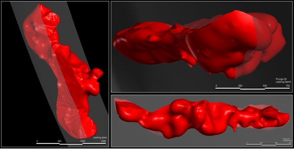
Note: West skarn mineralization in red hosts a mix of sulfide and oxides. Backbone fault in gray.
Figure 14-5: Broadtop Butte Mineralized Envelopes
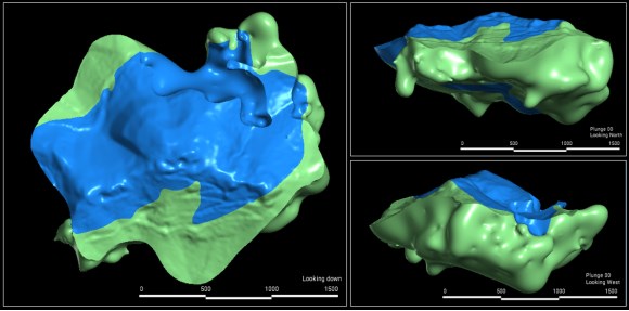
Note: Broadtop Butte skarn sulfide mineralization in green and porphyry oxidized mineralization in blue.
The envelopes and the drillhole traces were loaded into MineSight® to ensure proper tagging of the solids to actual drillhole locations. The mineral envelopes were used as a hard boundary in all cases for grade interpolation purposes, to prevent spreading of mineralization into the barren zone and vice versa.
|
14.3 Density for the East Deposit
The regression formulas used to calculate Specific Gravity (SGPR) from measured values by weight in air/weight in water are based on the 1,700 specific gravity data collected by Hudbay in and around the vicinity (i.e., barren zones bounding the deposit) of the East mineralized envelope.
Multi-regression models for the Hudbay ICP-MS data set were developed using grouping of the units based on their genetic affinities and their similar level of alterations. Exempt from this are the granodiorite, the andesite and the QMP which are geologically too distinct from the other lithologies. Figure 14-6 presents a typical cross section of the East Deposit with the sub-grouping used to predict density.
Figure 14-6: Typical Cross Section of East Deposit with Geological Units Looking North
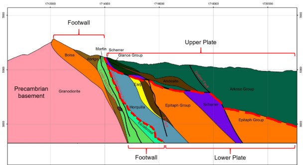
Table 14-4 presents a summary of the inputs used along with the results obtained from the Hudbay data set without specific gravity measurements.
|
Table 14-4: Regression Models, Formulas, & Statistics
| Hudbay ICP-MS data set | Predicted (Measured) | Predicted (Measured) | |||||||||
| Group | Formula | Mean | Min | Max | Group | Formula | Mean | Min | Max | ||
| Basement | SGPR = 2.3922 + 0.000298 * MNPPM + 0.00359 * MOPPM + 0.02638 * UPPM | 2.68 (2.65) |
2.52 (2.57) |
2.85 (2.85) |
Augusta data set | Basement | SGPR = 2.7040 - 78.2 * MOPCT | 2.62 (2.65) |
2.57 (2.57) |
2.70 (2.85) |
|
| Lower Plate |
SGPR = 2.5405 + 0.07552 * ALPCT - 0.000375 * LIPPM + 0.003861 * NIPPM - 0.2544 * TLPPM - 0.01532 * SCPPM + 0.004947 * SNPPM + 0.007131 * CAPCT | 2.76 (2.76) |
2.26 (2.26) |
3.55 (3.70) |
Lower Plate |
SGPR = 2.71994 + 0.01824 * AGPPM + 0.1163 * CUPCT + 1.225 * MOPCT + 0.2439 * ZNPCT | 2.77 (2.76) |
2.30 (2.30) |
3.78 (3.78) |
||
| Upper Plate |
SGPR = 2.6062 - 0.1735 * SNPPM - 0.00508 * AGPPM + 0.000088 * MNPPM + 0.007531 * SBPPM + 0.001071 * VPPM + 0.00615 * YPPM | 2.59 (2.59) |
1.97 (1.97) |
3.35 (3.35) |
Upper Plate |
SGPR = 2.59651 + 0.03363 * AGPPM + 0.4998 * CUPCT - 7.06 * MOPCT + 0.9903 * ZNPCT | 2.59 (2.59) |
1.97 (1.97) |
3.06 (3.06) |
||
| Andesite | SGPR = 1.8050 + 0.03619 * CAPCT - 0.1699 * CUPCT + 0.01294 * LAPPM - 0.004056 * MOPPM + 0.05223 * NBPPM - 2.738 * PPCT | 2.67 (2.68) |
2.15 (2.16) |
3.12 (3.09) |
Andesite | SGPR = 2.7649 - 0.03686 * AGPPM + 0.517 * ZNPCT | 2.67 (2.70) |
2.16 (2.16) |
3.08 (3.08) |
||
| QMP | SGPR = 2.6925 - 0.1185 * AGPPM + 0.003286 * ASPPM + 0.943 * HFPPM + 0.003984 * RBPPM + 0.5520 * TLPPM - 0.03300 * ZRPPM | 2.47 (2.53) |
2.11 (2.11) |
2.77 (2.76) |
QMP | SGPR = 2.55564 - 3.64 * MOPCT | 2.52 (2.54) |
2.19 (2.19) |
2.56 (2.64) |
||
| Note: Predicted density above and Measured density below and between ( ). | |||||||||||
A hybrid field in the drillhole file was populated with measured density and predicted density (measured always truncate predicted). Samples without measured or predicted value from the historical holes were attributed with the average density value of the subgroup.
14.4 Density for the Footwall skarn Zone, Peach-Elgin, West and Broadtop Butte Deposits
1,179 measurements of specific gravity have been conducted for samples taken at random from the 2020-2022 drilling program at the Copper World deposits. This data includes:
• 857 measurements by pycnometer from pulps at the SGS and ALS laboratories to be used at a later stage of the project to correlate with geochemistry.
• 323 measurements on 6-inch (15 cm) whole core samples, 64 of which were on samples without wax coating at the Skyline lab.
• 259 measurements on samples with wax coating at the Bureau Veritas and SGS laboratories.
Specific gravity measurements from competent pieces of core may not necessarily reflect in-situ density during the mining operation in unconsolidated ground with natural voids which is a common feature of the Broadtop Butte, West and Peach-Elgin deposits as well as for the footwall skarn zone in the East deposit. To quantify the potential for correction and validate the core box weight as a more accurate measure of in-situ density, the sources of information were compared where available.
|
For this purpose, all the samples located inside the various mineralization domains were selected from the 2020-2022 drilling campaign. A quality control process was conducted on the selected samples to remove erroneous box weight measurements. These errors occurred when the core boxes were not placed properly on the weigh scale. Only density values between 1.8 and 4.5 g/cm3 were retained. A total of 107,011 feet (32,617 m) of core box weights located within the 6 mineral envelopes were retained following this quality control check.
Table 14-5 summarizes the average adjusted densities for the core box estimates by deposit. The average in-situ value derived from these core box weight measurements will be used for resource estimation and mine planning purposes until sufficient pycnometer measurements have been obtained and correlated with geochemistry.
Table 14-5: Summary of Core Box Weight Measurements for the Copper World Deposits
| Mineralized Zone | Weighted Core Length (ft) |
Weighted Core Length (ft) |
In-Situ Density (g/cm3) |
| Footwall zone- (skarn) | 7,925 | 26,000 | 2.64 |
| Peach-Eling (skarn) | 4,233 | 13,889 | 2.57 |
| Elgin (porphyry) | 3,114 | 10,217 | 2.52 |
| Copper World (skarn) | 7,277 | 23,874 | 2.65 |
| Broadtop Butte (skarn) | 4,731 | 15,522 | 2.71 |
| Broadtop Butte (porphyry) | 5,337 | 17,509 | 2.53 |
14.5 Compositing
Assay intervals were regularized by compositing drillhole data within the interpreted geological and mineralized envelopes. The drillholes were typically assayed on intervals of 5 feet (<1.5 m) and a composite length of 25 feet (7.6 m) was selected as more appropriate to conduct interpolation into the 50 x 50 x 50 ft (15 x 15 x 15 m) block size selected to account for the proposed mining method (front-loading shovels). The compositing process was validated by comparing total length, density, and length-weighted average grade for each metal of the composites to the original assays.
14.6 Exploratory Data Analysis
Exploratory data analysis (EDA) includes basic statistical evaluation of the assays and composites for Cu, CuSS, Mo, Ag, Au, Fe, Mg, Mn, Pb, Zn, As, Ca, Na, P, S, Al, and K. The EDA was conducted separately for each mineralized envelope. The composite statistics for these variables are summarized in Table 14-8 and Table 14-9 of the block model validation section.
It is worth noting that Fe, Mg, Mn, Pb, Zn, As, Ca, Na, P, S, Al and K were also interpolated and validated in each of the deposits. These variables, together with Cu, CuSS, Mo, and Ag, were used as inputs to the machine-learning models. However, to be succinct, only the economic metals are detailed in this Technical Report.
14.7 Grade Capping
The deciles analysis (Parrish, 1997) method was used to define high-grade outliers and to assess the need for grade capping. It was conducted on the composites in the mineralized envelope. This method considers capping when the last decile of the population contains more than 40% of the metal and the last percentile contains more than 10% of the metal. Based on this analysis, gold, silver, and molybdenum were capped as detailed in Table 14-6. These capping values were selected to limit the weight of the high-grade outliers on the overall population.
|
Table 14-6: Capping Thresholds
| Gold | Silver | Molybdenum | ||||||||
| ENVLP | Capping threshold |
# of composites capped |
Metal loss |
Capping threshold |
# of composites capped |
Metal loss |
Capping threshold |
# of composites capped |
Metal loss |
|
| East Deposit | 5 | 0.2 | 3 | 1.20% | 50 | 10 | 9.1% | 800 | 11 | 1.40% |
| 6 | 0.33 | 2 | 0.20% | 55 | 11 | 0.32% | 2100 | 16 | 1.30% | |
| 7 | 0.089 | 1 | 0.00% | 10 | 3 | 4.0% | 450 | 4 | 2.10% | |
| 8 | 0.2 | 2 | 3.50% | - | - | - | 710 | 3 | 5.50% | |
| 10 | 0.2 | 2 | 4.30% | - | - | - | - | - | - | |
| 11 | - | - | - | 35 | 4 | 1.60% | 300 | 3 | 2.90% | |
| Other Copper World Deposits | 12 | 0.22 | 9 | 2.1% | 40 | 4 | 7.4% | 600 | 9 | 1.8% |
| 13 | 0.15 | 2 | 1.4% | 15 | 3 | 4.0% | - | - | - | |
| 14 | 0.15 | 1 | 14.0% | 35 | 2 | 1.2% | - | - | - | |
| 15 | 0.3 | 2 | 3.5% | - | - | - | 850 | 8 | 4.2% | |
| 16 | 0.2 | 4 | 1.2% | 35 | 2 | 2.5% | 1,055 | 5 | 0.7% | |
14.8 Variography
Down-hole and directional pairwise relative variograms for all elements were created for each individual mineral envelope using MineSight Sigma software. The major, semi-major, and minor axes were built from variogram maps. A combination of nugget and two-nested spherical models were adjusted in all cases. Once generated, a systematic visual check was conducted to ensure that the search ellipsoid would be correctly oriented with respect to the geometry of the mineral envelopes.
14.9 Grade Estimation & Interpolation Methods
The block model consists of regular blocks 50 ft along strike by 50 ft across strike by 50 ft vertically (15 x 15 x 15 m). The block dimensions were selected to match the expected smallest mining unit (SMU) for all the deposits to be mined for the Project. Where a block was intersected by more than one interpolation domain, the domain wireframes were used to assign the percentage of the block that belongs to each domain. Figure 14-7 presents an example of the ore percentage model with 70% of the block inside ENVLP 5 and 30% is within ENVLP 6.
|
Figure 14-7: Ore Percentage Example
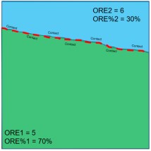
In all cases, both nearest neighbor (NN) and ordinary kriging (OK) grade interpolations were completed on the uncapped and capped grades using a strict composite and block matching code by mineralized envelope, and three passes with increasing minimum information requirements (Table 14-7).
The search passes were selected to ensure the best local estimates recognizing that OK has a smoothing effect and making no attempt during interpolation to reduce this smoothing as it would negatively impact the quality of the local estimates. Over-smoothing is addressed through the post-processing of the model described in Section 14.13.
Table 14-7: Search Ellipse Parameters
| Pass #1 (fill pass) | Pass #2 | Pass #3 | |
| Search Ellipse | ≈150% of variogram range |
75% of variogram range |
50% of variogram range |
| Minimum number of composites | 1 | 16 | 16 |
| Maximum number of composites | 32 | 32 | 32 |
| Maximum number of composites per hole | 6 | 6 | 6 |
| Declustering | no | yes | yes |
| Maximum number of composites per quadrant | no | 24 | 18 |
| Minimum number of quadrants | 1 | 2 | 1 |
14.10 Grade Estimation Validation
The grade estimation process was validated for each mineralized envelope to ensure appropriate honoring of the input data and subsequent unbiased resource reporting through the following steps:
• Visual checks of appropriate honoring of the input data but acknowledging that some natural smoothing should occur between samples as the grade of a sample in the middle of a block is not the average grade of the block.
• Absence of global bias by comparing the mean grade estimated by kriging to the original composite average grade and to a declustered grade obtained from a nearest neighbor interpolation.
|
• Assessment of the level of smoothing in the kriged model and correction for over-smoothing as per variogram model assumptions by domain of consistent drilling density and statistical properties.
14.11 Visual Inspection
Visual inspection of block grade versus composited data was systematically conducted in section view. This check confirmed a good reproduction of the data by the model. As an example, cross sections (looking north) are presented in Figure 14-8 to Figure 14-12.
Figure 14-8: East Deposit - OK Model & Copper Grade Composites E-W Section View
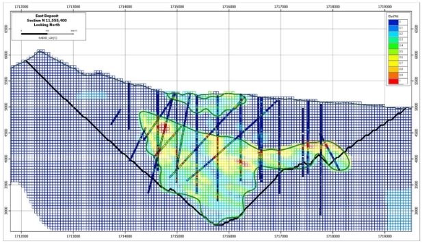
|
Figure 14-9: Peach-Elgin Deposit - OK Model & Copper Grade Composites E-W Section View
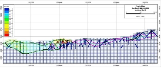
Figure 14-10: West Deposit - OK Model & Copper Grade Composites E-W Section View
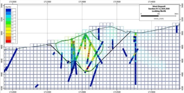
|
Figure 14-11: Broadtop Butte Deposit - OK Model & Copper Grade Composites E-W Section View
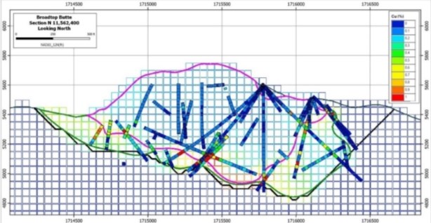
Figure 14-12: Footwall Zone of the East Deposit - OK Model & Copper Grade Composites E-W Section View
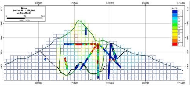
14.12 Global Bias Checks
This validation step consists of comparing the global average grade of each element between the composites, the nearest neighbor and the kriged block estimates.
|
A global check was performed to verify that the kriged mean block estimate did not present any bias when compared to the composites and the nearest neighbor model. Differences between the composites, the NN and OK grades were acceptable. The comparison of the mean and variance for each metal between the DDHs, the composites, the NN and OK models is summarized in Table 14-8 and Table 14-9.
14.13 Smoothing Assessment
The visual validation conducted in section view confirmed that the block grade interpolation is consistent with the supporting composite data. The larger number of composites used for grade estimation in the block model significantly improves the individual block grade estimates, but at the same time results in a much smoother model, requiring a careful assessment and in many cases a post-processing of the OK estimates.
The extent of grade 'over-smoothing' in the model was investigated based on material differences in grade distribution and/or drilling density. The mean and variance of the kriged estimates were compared to the variance of the composites after declustering. The expected true variance between SMUs was calculated from the variogram models.
Over-smoothing is a normal outcome of a sound interpolation method when the drill spacing is not sufficient to address the short-range variability in the metal grade distribution. Smoothing will gradually reduce as additional infill drilling is performed during the definition drilling phases.
14.14 Smoothing Correction
Using the smoothed OK estimates results in an erroneous grade-tonnage curve, and reporting resources or reserves at a cut-off grade different than 0% would produce biased estimates, usually over-estimating tonnes, and under-estimating grades.
An indirect log-normal correction was used to perform a change of support on the kriged models to obtain unbiased grade tonnage curves for copper, gold, silver and molybdenum. This correction is only valid globally and provides poorer local estimates than the smoothed OK model. However, it does not materially alter the global average grade within each zone and provides the correct grade-tonnage curve for the variogram models fitted on the drillhole data. It is an appropriate method to predict the recoverable tonnage and grade, such as the mined volume over three months of production, which should be a realistic aim for a long-term reserve model based on exploration drilling. This approach was not deemed necessary for the elements only interpolated for the purpose of geometallurgical modeling as flotation recovery formulation and blending requirements are valid for large volumes and hence correcting for over-smoothing is not deemed as critical as for the metals with economic value.
For some of the elements, the correction did not fully attain the targeted variance, reflecting that the log-normal model does not perfectly fit these elements. However, the targeted variance was reached within very close limits in most cases, as illustrated in Table 14-10 and Table 14-11.
|
Table 14-8: Global Statistics of the East Deposit
| Footwall+Bolsa (ENVLP = 5) | Lower Plate (ENVLP = 6) | Lower plate middle oxide (ENVLP = 7) | |||||||||||||||||
| Min | Max | Mean | Median | Variance | CV | Min | Max | Mean | Median | Variance | CV | Min | Max | Mean | Median | Variance | CV | ||
| 25' Composites | Cu (%) | 0.001 | 9.421 | 0.45 | 0.254 | 0.3881 | 1.38 | 0.003 | 5.559 | 0.446 | 0.291 | 0.2134 | 1.04 | 0.066 | 2.028 | 0.431 | 0.375 | 0.063 | 0.58 |
| CuSS (%) | 0 | 4.233 | 0.241 | 0.112 | 0.1149 | 1.41 | 0.001 | 1.2 | 0.049 | 0.027 | 0.0071 | 1.71 | 0.01 | 1.919 | 0.261 | 0.218 | 0.0467 | 0.83 | |
| Ag (PPM) | 0.05 | 772.83 | 3.534 | 1.809 | 237.1908 | 4.36 | 0.05 | 72.98 | 5.07 | 3.145 | 38.2913 | 1.22 | 0.461 | 27.416 | 2.687 | 1.903 | 6.7548 | 0.97 | |
| Capped Ag | 0.05 | 50 | 3.212 | 1.809 | 25.9081 | 1.58 | 0.05 | 55 | 5.054 | 3.145 | 36.4695 | 1.19 | 0.461 | 10 | 2.572 | 1.903 | 3.4484 | 0.72 | |
| Au (PPM) | 0.003 | 0.379 | 0.011 | 0.007 | 0.0003 | 1.45 | 0.003 | 0.497 | 0.027 | 0.014 | 0.0014 | 1.38 | 0.003 | 0.089 | 0.012 | 0.01 | 0.0001 | 0.81 | |
| Capped Au | 0.003 | 0.2 | 0.011 | 0.007 | 0.0002 | 1.26 | 0.003 | 0.33 | 0.027 | 0.014 | 0.0014 | 1.36 | 0.003 | 0.089 | 0.012 | 0.01 | 0.0001 | 0.81 | |
| Mo (PPM) | 0.298 | 1548.337 | 74.81 | 42.056 | 11510.1 | 1.43 | 0.847 | 4464.424 | 147.045 | 92.084 | 47925 | 1.49 | 1.672 | 700 | 77.395 | 49.048 | 8052 | 1.16 | |
| Capped Mo | 0.298 | 800 | 73.797 | 42.056 | 9567.6 | 1.33 | 0.847 | 2100 | 145.216 | 92.084 | 38066 | 1.34 | 1.672 | 450 | 75.763 | 49.048 | 6533 | 1.07 | |
| Al (%) | 0.04 | 9.12 | 3.52 | 3.17 | 4.84 | 0.62 | 0.05 | 9.11 | 2.67 | 2.31 | 3.32 | 0.68 | 0.27 | 4.63 | 2.01 | 1.84 | 1.16 | 0.53 | |
| As (PPM) | 0.25 | 384.1 | 13.231 | 7.2 | 551 | 1.77 | 0.5 | 410.57 | 11.339 | 6.28 | 478.5 | 1.93 | 2.02 | 96.71 | 14.668 | 11.56 | 148.7 | 0.83 | |
| Ca (%) | 0.005 | 40.026 | 9.571 | 8.948 | 86.51 | 0.97 | 0.754 | 38.801 | 17.325 | 17.627 | 67.38 | 0.47 | 0.97 | 26.179 | 12.119 | 11.787 | 29.67 | 0.45 | |
| Fe (%) | 0.203 | 26.158 | 5.078 | 4.015 | 13.12 | 0.71 | 0.114 | 21.245 | 3.043 | 2.261 | 6.31 | 0.83 | 1.514 | 13.946 | 5.917 | 5.317 | 7.01 | 0.45 | |
| Mg (%) | 0.022 | 13.664 | 1.939 | 1.034 | 5.84 | 1.25 | 0.048 | 15.288 | 3.912 | 3.233 | 7.79 | 0.71 | 0.189 | 9.775 | 1.783 | 1.444 | 1.86 | 0.76 | |
| Pb (%) | 0 | 0.325 | 0.004 | 0.001 | 0 | 3.75 | 0 | 0.371 | 0.004 | 0.001 | 0 | 4.41 | 0 | 0.159 | 0.003 | 0 | 0 | 4.54 | |
| Zn (%) | 0 | 1.567 | 0.041 | 0.02 | 0.01 | 2.03 | 0.001 | 1.256 | 0.039 | 0.021 | 0 | 1.65 | 0.009 | 0.37 | 0.037 | 0.021 | 0 | 1.46 | |
| P (%) | 0.001 | 0.538 | 0.055 | 0.04 | 0 | 0.87 | 0.002 | 0.469 | 0.045 | 0.035 | 0 | 0.89 | 0.01 | 0.183 | 0.044 | 0.036 | 0 | 0.66 | |
| K (%) | 0.005 | 7.092 | 2.056 | 1.534 | 3.59 | 0.92 | 0.005 | 7.488 | 1.25 | 0.706 | 1.68 | 1.04 | 0.007 | 4.254 | 0.891 | 0.532 | 0.81 | 1.01 | |
| Na (%) | 0.001 | 2.641 | 0.204 | 0.078 | 0.09 | 1.51 | 0.002 | 1.496 | 0.176 | 0.072 | 0.05 | 1.25 | 0.004 | 0.363 | 0.042 | 0.025 | 0 | 1.25 | |
| S (%) | 0.01 | 16.31 | 0.254 | 0.03 | 0.59 | 3.03 | 0.01 | 10.27 | 0.642 | 0.225 | 1.13 | 1.66 | 0.05 | 4.17 | 0.212 | 0.05 | 0.27 | 2.44 | |
| MN (PPM) | 33.10 | 13106.90 | 2386.58 | 1859.60 | 5086790.15 | 0.95 | 130.40 | 10000.10 | 2620.31 | 2292.80 | 2836005.29 | 0.64 | 599.10 | 8390.70 | 3011.34 | 2911.10 | 2082006.09 | 0.48 | |
| NN Model | Cu (%) | 0.001 | 9.421 | 0.398 | 0.228 | 0.2841 | 1.34 | 0.003 | 5.559 | 0.385 | 0.235 | 0.1823 | 1.11 | 0.066 | 2.028 | 0.42 | 0.362 | 0.0562 | 0.56 |
| CuSS (%) | 0.001 | 3.206 | 0.131 | 0.075 | 0.0339 | 1.4 | 0.001 | 1.2 | 0.037 | 0.02 | 0.0035 | 1.59 | 0.01 | 1.919 | 0.241 | 0.206 | 0.0339 | 0.76 | |
| Ag (PPM) | 0.05 | 772.83 | 3.362 | 1.68 | 62.8849 | 2.36 | 0.05 | 72.98 | 4.488 | 2.632 | 33.2698 | 1.29 | 0.461 | 27.416 | 2.596 | 1.825 | 5.9976 | 0.94 | |
| Capped Ag | 0.05 | 50 | 3.218 | 1.68 | 24.7506 | 1.55 | 0.05 | 55 | 4.477 | 2.632 | 31.9903 | 1.26 | 0.461 | 10 | 2.496 | 1.825 | 3.393 | 0.74 | |
| Au (PPM) | 0.003 | 0.379 | 0.013 | 0.008 | 0.0003 | 1.33 | 0.003 | 0.497 | 0.024 | 0.011 | 0.0012 | 1.45 | 0.003 | 0.089 | 0.012 | 0.01 | 0.0002 | 0.69 | |
| Capped Au | 0.003 | 0.2 | 0.013 | 0.008 | 0.0002 | 1.15 | 0.003 | 0.33 | 0.024 | 0.011 | 0.0012 | 1.44 | 0.003 | 0.089 | 0.012 | 0.01 | 0.0001 | 0.69 | |
| Mo (PPM) | 0.298 | 1548.337 | 87.085 | 49.055 | 15537.6 | 1.43 | 0.847 | 4464.424 | 151.077 | 88 | 64248 | 1.68 | 1.672 | 700 | 73.372 | 46.24 | 6914 | 1.13 | |
| Capped Mo | 0.298 | 800 | 85.008 | 49.055 | 11652.1 | 1.27 | 0.847 | 2100 | 147.762 | 88 | 45283 | 1.44 | 1.672 | 450 | 72.035 | 46.24 | 5656 | 1.04 | |
| Al (%) | 0.03 | 9.13 | 3.23 | 2.67 | 5.38 | 0.72 | 0.05 | 9.11 | 2.59 | 2.22 | 3.20 | 0.69 | 0.11 | 4.81 | 1.96 | 1.83 | 1.06 | 0.52 | |
| As (PPM) | 0.25 | 384.1 | 12.763 | 7.32 | 541.2 | 1.82 | 0.5 | 410.57 | 11.618 | 6.2 | 656.8 | 2.21 | 2.02 | 96.71 | 13.678 | 11.6 | 112.5 | 0.78 | |
| Ca (%) | 0.005 | 40.026 | 13.558 | 13.535 | 140 | 0.87 | 0.754 | 38.156 | 17.641 | 17.765 | 64.94 | 0.46 | 0.97 | 26.179 | 12.183 | 11.595 | 28.71 | 0.44 | |
| Fe (%) | 0.203 | 26.158 | 4.857 | 3.424 | 17.5 | 0.86 | 0.114 | 21.245 | 3.068 | 2.275 | 6.68 | 0.84 | 1.514 | 13.946 | 6.342 | 6.411 | 7 | 0.42 | |
| Mg (%) | 0.022 | 13.664 | 2.102 | 0.968 | 6.49 | 1.21 | 0.048 | 15.288 | 3.951 | 3.262 | 8.21 | 0.73 | 0.189 | 9.775 | 1.775 | 1.411 | 1.7 | 0.73 | |
| Pb (%) | 0 | 0.325 | 0.004 | 0.002 | 0 | 3.22 | 0 | 0.371 | 0.004 | 0.001 | 0 | 4.49 | 0 | 0.159 | 0.004 | 0 | 0 | 4.55 | |
| Zn (%) | 0 | 1.289 | 0.038 | 0.019 | 0.01 | 2.03 | 0.001 | 1.256 | 0.04 | 0.021 | 0.01 | 2.05 | 0.009 | 0.37 | 0.038 | 0.023 | 0 | 1.5 | |
| P (%) | 0.001 | 0.538 | 0.053 | 0.037 | 0 | 0.88 | 0.002 | 0.469 | 0.045 | 0.035 | 0 | 0.88 | 0.01 | 0.183 | 0.046 | 0.038 | 0 | 0.62 | |
| K (%) | 0.005 | 7.092 | 1.889 | 0.841 | 4.21 | 1.09 | 0.005 | 7.488 | 1.181 | 0.632 | 1.58 | 1.06 | 0.007 | 4.254 | 0.755 | 0.441 | 0.68 | 1.09 | |
| Na (%) | 0.001 | 2.641 | 0.26 | 0.051 | 0.17 | 1.6 | 0.002 | 1.496 | 0.161 | 0.056 | 0.05 | 1.32 | 0.004 | 0.363 | 0.043 | 0.021 | 0 | 1.29 | |
| S (%) | 0.01 | 16.31 | 0.676 | 0.06 | 2.06 | 2.12 | 0.01 | 10.27 | 0.673 | 0.25 | 1.16 | 1.6 | 0.05 | 4.17 | 0.157 | 0.05 | 0.15 | 2.51 | |
| MN (PPM) | 33.10 | 8589.93 | 4106.24 | 1525.00 | 15539214.20 | 0.96 | 77.18 | 8589.93 | 4905.33 | 8589.93 | 13764491.93 | 0.76 | 243.80 | 8589.93 | 6647.93 | 8589.93 | 10254844.94 | 0.48 | |
|
| Footwall+Bolsa (ENVLP = 5) | Lower Plate (ENVLP = 6) | Lower plate middle oxide (ENVLP = 7) | |||||||||||||||||
| Min | Max | Mean | Median | Variance | CV | Min | Max | Mean | Median | Variance | CV | Min | Max | Mean | Median | Variance | CV | ||
| OK Model | Cu (%) | 0.004 | 5.92 | 0.39 | 0.335 | 0.0655 | 0.66 | 0.043 | 2.257 | 0.391 | 0.335 | 0.048 | 0.56 | 0.138 | 0.958 | 0.421 | 0.406 | 0.0182 | 0.32 |
| CuSS (%) | 0.004 | 1.567 | 0.163 | 0.125 | 0.0172 | 0.8 | 0.002 | 0.871 | 0.039 | 0.03 | 0.0013 | 0.91 | 0.055 | 0.733 | 0.258 | 0.248 | 0.0108 | 0.4 | |
| Ag (PPM) | 0.355 | 65.448 | 3.357 | 2.56 | 9.7344 | 0.93 | 0.08 | 40.923 | 4.523 | 3.785 | 8.281 | 0.64 | 0.752 | 15.836 | 2.677 | 2.325 | 1.4544 | 0.45 | |
| Capped Ag | 0.355 | 32.422 | 3.165 | 2.553 | 5.8564 | 0.76 | 0.08 | 34.642 | 4.512 | 3.784 | 8.1682 | 0.63 | 0.752 | 6.856 | 2.522 | 2.27 | 0.8372 | 0.36 | |
| Au (PPM) | 0.003 | 0.153 | 0.012 | 0.011 | 0.00005 | 0.58 | 0.003 | 0.231 | 0.025 | 0.021 | 0.0002 | 0.6 | 0.003 | 0.036 | 0.011 | 0.011 | 0.00002 | 0.32 | |
| Capped Au | 0.003 | 0.114 | 0.012 | 0.011 | 0.00004 | 0.54 | 0.003 | 0.184 | 0.025 | 0.021 | 0.0002 | 0.6 | 0.003 | 0.036 | 0.011 | 0.011 | 0.00002 | 0.32 | |
| Mo (PPM) | 4.13 | 632.76 | 85.106 | 72.058 | 3131.75 | 0.66 | 3.143 | 1844.072 | 151.684 | 135.085 | 8577 | 0.61 | 14.212 | 395.424 | 72.697 | 61.931 | 2292 | 0.66 | |
| Capped Mo | 4.13 | 551.485 | 83.528 | 71.78 | 2782.46 | 0.63 | 3.143 | 1194.092 | 148.501 | 134.823 | 6815 | 0.56 | 14.212 | 309.618 | 71.476 | 61.874 | 1979 | 0.62 | |
| Al (%) | 0.23 | 7.47 | 3.35 | 3.22 | 2.51 | 0.47 | 0.14 | 8.30 | 2.60 | 2.45 | 1.39 | 0.45 | 0.28 | 3.97 | 2.06 | 1.97 | 0.29 | 0.26 | |
| As (PPM) | 0.5 | 191.457 | 13.134 | 10.855 | 82.68 | 0.69 | 1 | 165.63 | 11.395 | 7.955 | 115.4 | 0.94 | 5.382 | 37.218 | 14.023 | 13.521 | 11.88 | 0.25 | |
| Ca (%) | 0.005 | 38.384 | 10.902 | 10.655 | 82.21 | 0.83 | 2.054 | 36.221 | 17.365 | 17.744 | 32.35 | 0.33 | 3 | 21.309 | 12.173 | 12.276 | 6.49 | 0.21 | |
| Fe (%) | 0.512 | 14.411 | 4.57 | 4.442 | 4.37 | 0.46 | 0.184 | 17.121 | 3.092 | 2.519 | 3.26 | 0.58 | 1.946 | 9.975 | 6.273 | 6.464 | 2.29 | 0.24 | |
| Mg (%) | 0.042 | 11.102 | 2.022 | 1.656 | 2.34 | 0.76 | 0.33 | 12.093 | 3.973 | 3.481 | 3.69 | 0.48 | 0.765 | 6.399 | 1.715 | 1.56 | 0.33 | 0.33 | |
| Pb (%) | 0 | 0.124 | 0.004 | 0.002 | 0 | 1.32 | 0 | 0.245 | 0.004 | 0.002 | 0 | 2.33 | 0 | 0.088 | 0.004 | 0.001 | 0 | 2.4 | |
| Zn (%) | 0.001 | 0.441 | 0.039 | 0.031 | 0 | 0.98 | 0.003 | 0.735 | 0.038 | 0.031 | 0 | 0.78 | 0.015 | 0.216 | 0.036 | 0.026 | 0 | 0.69 | |
| P (%) | 0.002 | 0.222 | 0.055 | 0.048 | 0 | 0.59 | 0.007 | 0.238 | 0.045 | 0.04 | 0 | 0.48 | 0.013 | 0.128 | 0.044 | 0.042 | 0 | 0.31 | |
| K (%) | 0.005 | 6.155 | 1.96 | 1.463 | 2.71 | 0.84 | 0.005 | 5.87 | 1.176 | 0.909 | 0.72 | 0.72 | 0.049 | 2.689 | 0.787 | 0.63 | 0.22 | 0.59 | |
| Na (%) | 0.003 | 1.958 | 0.243 | 0.106 | 0.1 | 1.32 | 0.004 | 0.946 | 0.164 | 0.129 | 0.02 | 0.8 | 0.009 | 0.181 | 0.042 | 0.039 | 0 | 0.41 | |
| S (%) | 0.01 | 8.521 | 0.503 | 0.259 | 0.3 | 1.1 | 0.029 | 6.954 | 0.681 | 0.43 | 0.47 | 1.01 | 0.05 | 3.526 | 0.176 | 0.122 | 0.03 | 0.95 | |
| MN (PPM) | 33.10 | 11268.80 | 2097.07 | 2155.34 | 1803312.56 | 0.64 | 189.88 | 7772.66 | 2507.76 | 2356.17 | 1219016.63 | 0.44 | 595.68 | 6957.18 | 2929.27 | 3006.69 | 772616.52 | 0.30 | |
| Lower plate bottom oxide (ENVLP = 8) | Porphyry (ENVLP = 10) | Upper plate bottom (ENVLP = 11) | |||||||||||||||||
| Min | Max | Mean | Median | Variance | CV | Min | Max | Mean | Median | Variance | CV | Min | Max | Mean | Median | Variance | CV | ||
| 25' Composites | Cu (%) | 0.015 | 3.424 | 0.538 | 0.434 | 0.1823 | 0.79 | 0.001 | 5.006 | 0.309 | 0.179 | 0.1225 | 1.13 | 0.002 | 2.45 | 0.206 | 0.152 | 0.04537 | 1.03 |
| CuSS (%) | 0.003 | 1.397 | 0.221 | 0.152 | 0.0534 | 1.04 | 0.003 | 1.264 | 0.099 | 0.066 | 0.0169 | 1.31 | 0.001 | 2.43 | 0.103 | 0.065 | 0.02103 | 1.41 | |
| Ag (PPM) | 0.367 | 31.118 | 5.065 | 3.887 | 15.3037 | 0.77 | 0.05 | 31.356 | 2.634 | 1.188 | 12.3341 | 1.33 | 0.237 | 51.086 | 5.395 | 3.882 | 34.2225 | 1.08 | |
| Capped Ag | 0.367 | 31.118 | 5.065 | 3.887 | 15.3037 | 0.77 | 0.05 | 31.356 | 2.634 | 1.188 | 12.3341 | 1.33 | 0.237 | 35 | 5.324 | 3.882 | 29.0521 | 1.01 | |
| Au (PPM) | 0.003 | 0.37 | 0.044 | 0.03 | 0.0021 | 1.04 | 0.003 | 0.348 | 0.016 | 0.006 | 0.0001 | 1.64 | 0.003 | 0.019 | 0.005 | 0.004 | 0.00001 | 0.68 | |
| Capped Au | 0.003 | 0.2 | 0.043 | 0.03 | 0.0014 | 0.88 | 0.003 | 0.2 | 0.015 | 0.006 | 0.0006 | 1.64 | 0.003 | 0.019 | 0.005 | 0.004 | 0.00001 | 0.68 | |
| Mo (PPM) | 1.125 | 1338.504 | 81.473 | 48.683 | 10825.5 | 1.64 | 1.125 | 984.64 | 102.346 | 57.78 | 15795 | 1.23 | 0.326 | 504.826 | 21.193 | 5.31 | 1866.672 | 2.04 | |
| Capped Mo | 1.125 | 710 | 77.744 | 48.683 | 11047.9 | 1.35 | 1.125 | 984.64 | 102.346 | 57.78 | 15795 | 1.23 | 0.326 | 300 | 20.594 | 5.31 | 1426.573 | 1.83 | |
| Al (%) | 0.02 | 6.27 | 1.58 | 1.34 | 1.52 | 0.78 | 1.10 | 7.77 | 5.35 | 5.40 | 1.74 | 0.25 | 1.36 | 8.71 | 6.45 | 6.48 | 1.73 | 0.20 | |
| As (PPM) | 0.5 | 740.91 | 20.481 | 8.428 | 6346 | 3.89 | 0.7 | 147.8 | 11.741 | 7.609 | 337.7 | 1.57 | 4 | 426.5 | 26.889 | 17.062 | 1674 | 1.52 | |
| Ca (%) | 7.574 | 36.86 | 21.046 | 20.294 | 57.05 | 0.36 | 0.045 | 21.58 | 1.596 | 1.142 | 5.47 | 1.46 | 0.707 | 28.007 | 5.452 | 4.316 | 20.96 | 0.84 | |
| Fe (%) | 0.318 | 11.97 | 5.065 | 4.725 | 9.58 | 0.61 | 0.503 | 6.82 | 1.337 | 1.177 | 0.38 | 0.46 | 0.786 | 10.854 | 3.902 | 3.576 | 1.96 | 0.36 | |
| Mg (%) | 0.047 | 7.373 | 2.272 | 1.884 | 2.97 | 0.76 | 0.068 | 4.504 | 0.38 | 0.264 | 0.23 | 1.25 | 0.231 | 4.603 | 1.192 | 0.794 | 0.72 | 0.71 | |
| Pb (%) | 0 | 0.576 | 0.008 | 0.001 | 0 | 7.35 | 0 | 0.207 | 0.003 | 0.001 | 0 | 4.73 | 0.001 | 0.733 | 0.041 | 0.016 | 0.01 | 1.92 | |
| Zn (%) | 0.004 | 0.203 | 0.026 | 0.022 | 0 | 0.85 | 0.001 | 0.211 | 0.01 | 0.006 | 0 | 1.71 | 0.006 | 0.995 | 0.105 | 0.055 | 0.02 | 1.24 | |
| P (%) | 0.002 | 0.326 | 0.044 | 0.034 | 0 | 0.97 | 0.005 | 0.059 | 0.025 | 0.026 | 0 | 0.29 | 0.022 | 0.29 | 0.118 | 0.094 | 0 | 0.52 | |
| K (%) | 0.005 | 2.311 | 0.366 | 0.141 | 0.26 | 1.4 | 0.324 | 7.957 | 4.44 | 4.48 | 1.03 | 0.23 | 0.006 | 8.234 | 4.446 | 4.545 | 2.1 | 0.33 | |
| Na (%) | 0.002 | 0.363 | 0.049 | 0.013 | 0.01 | 1.67 | 0.01 | 2.732 | 0.805 | 0.318 | 0.67 | 1.02 | 0.006 | 2.811 | 0.411 | 0.242 | 0.19 | 1.06 | |
| S (%) | 0.05 | 2.44 | 0.227 | 0.081 | 0.13 | 1.59 | 0.01 | 1.91 | 0.135 | 0.05 | 0.05 | 1.68 | 0.01 | 5.75 | 0.414 | 0.05 | 0.68 | 2 | |
| MN (PPM) | 870.00 | 8839.20 | 4122.07 | 4363.60 | 2967191.65 | 0.42 | 52.40 | 7696.00 | 399.11 | 231.20 | 473043.35 | 1.72 | 307.00 | 8186.50 | 1501.46 | 1269.00 | 855184.86 | 0.62 | |
|
|
|
|
Footwall+Bolsa (ENVLP = 5) |
Lower Plate (ENVLP = 6) |
Lower plate middle oxide (ENVLP = 7) |
|||||||||||||||
|
|
|
Min |
Max |
Mean |
Median |
Variance |
CV |
Min |
Max |
Mean |
Median |
Variance |
CV |
Min |
Max |
Mean |
Median |
Variance |
CV |
|
NN Model |
Cu (%) |
0.015 |
3.424 |
0.469 |
0.358 |
0.1632 |
0.86 |
0.001 |
5.006 |
0.29 |
0.176 |
0.09 |
1.03 |
0.002 |
2.45 |
0.217 |
0.153 |
0.06554 |
1.18 |
|
CuSS (%) |
0.003 |
1.212 |
0.175 |
0.133 |
0.0266 |
0.93 |
0.001 |
1.264 |
0.081 |
0.052 |
0.0102 |
1.26 |
0.001 |
2.43 |
0.104 |
0.064 |
0.03028 |
1.67 |
|
|
Ag (PPM) |
0.367 |
31.118 |
4.637 |
3.64 |
13.1406 |
0.78 |
0.05 |
31.356 |
2.253 |
1.118 |
9.5172 |
1.37 |
0.237 |
51.086 |
5.921 |
3.94 |
49.35053 |
1.19 |
|
|
Capped Ag |
0.367 |
31.118 |
4.637 |
3.64 |
13.1406 |
0.78 |
0.05 |
31.356 |
2.253 |
1.118 |
9.5172 |
1.37 |
0.237 |
35 |
5.748 |
3.94 |
36.71148 |
1.05 |
|
|
Au (PPM) |
0.003 |
0.37 |
0.035 |
0.024 |
0.0013 |
1.04 |
0.003 |
0.348 |
0.012 |
0.005 |
0.0005 |
2.08 |
0.003 |
0.019 |
0.005 |
0.004 |
0.00001 |
0.67 |
|
|
Capped Au |
0.003 |
0.2 |
0.034 |
0.024 |
0.001 |
0.91 |
0.003 |
0.2 |
0.011 |
0.005 |
0.0003 |
1.65 |
0.003 |
0.019 |
0.005 |
0.004 |
0.00001 |
0.67 |
|
|
Mo (PPM) |
1.125 |
1338.504 |
92.031 |
53.32 |
18968.5 |
1.5 |
1.125 |
984.64 |
108.695 |
55.08 |
17981 |
1.23 |
0.326 |
504.826 |
19.665 |
5 |
1867.02 |
2.2 |
|
|
Capped Mo |
1.125 |
710 |
89.129 |
53.32 |
13756.5 |
1.32 |
1.125 |
984.64 |
108.695 |
55.08 |
17981 |
1.23 |
0.326 |
300 |
18.881 |
5 |
1280.35 |
1.9 |
|
|
Al (%) |
0.02 |
6.27 |
1.35 |
1.13 |
1.24 |
0.83 |
0.45 |
7.46 |
5.03 |
5.04 |
1.75 |
0.26 |
0.25 |
9.23 |
6.17 |
6.45 |
2.59 |
0.26 |
|
|
As (PPM) |
0.5 |
740.91 |
13.413 |
8.71 |
1569 |
2.95 |
0.7 |
147.8 |
12.535 |
8.04 |
413.9 |
1.62 |
4 |
426.5 |
33.951 |
17.64 |
3175 |
1.66 |
|
|
Ca (%) |
7.574 |
36.86 |
21.591 |
20.292 |
51.87 |
0.33 |
0.045 |
21.58 |
2.12 |
1.395 |
10.4 |
1.52 |
0.707 |
28.007 |
4.976 |
4.17 |
14.39 |
0.76 |
|
|
Fe (%) |
0.318 |
11.97 |
4.983 |
4.812 |
9.31 |
0.61 |
0.503 |
6.82 |
1.496 |
1.236 |
0.77 |
0.59 |
0.786 |
10.854 |
3.963 |
3.647 |
1.66 |
0.32 |
|
|
Mg (%) |
0.047 |
7.373 |
2.098 |
1.564 |
2.49 |
0.75 |
0.068 |
4.504 |
0.417 |
0.283 |
0.24 |
1.17 |
0.231 |
4.603 |
1.171 |
0.788 |
0.65 |
0.69 |
|
|
Pb (%) |
0 |
0.576 |
0.003 |
0.001 |
0 |
8.84 |
0 |
0.207 |
0.002 |
0.001 |
0 |
2.15 |
0.001 |
0.733 |
0.038 |
0.016 |
0 |
1.67 |
|
|
Zn (%) |
0.004 |
0.203 |
0.023 |
0.02 |
0 |
0.7 |
0.001 |
0.211 |
0.013 |
0.006 |
0 |
1.96 |
0.006 |
0.995 |
0.099 |
0.055 |
0.02 |
1.29 |
|
|
P (%) |
0.002 |
0.326 |
0.035 |
0.028 |
0 |
0.83 |
0.005 |
0.059 |
0.024 |
0.024 |
0 |
0.34 |
0.022 |
0.29 |
0.126 |
0.096 |
0 |
0.51 |
|
|
K (%) |
0.005 |
2.311 |
0.306 |
0.073 |
0.22 |
1.52 |
0.324 |
7.957 |
4.36 |
4.422 |
1.24 |
0.25 |
0.006 |
8.234 |
4.606 |
4.605 |
1.73 |
0.29 |
|
|
Na (%) |
0.002 |
0.363 |
0.045 |
0.014 |
0.01 |
1.63 |
0.01 |
2.732 |
0.626 |
0.248 |
0.49 |
1.12 |
0.006 |
2.811 |
0.462 |
0.325 |
0.22 |
1.02 |
|
|
S (%) |
0.05 |
2.44 |
0.203 |
0.07 |
0.11 |
1.62 |
0.01 |
1.91 |
0.205 |
0.05 |
0.1 |
1.56 |
0.01 |
5.75 |
0.339 |
0.05 |
0.45 |
1.99 |
|
|
MN (PPM) |
229.40 |
8589.93 |
7552.40 |
8589.93 |
6248475.39 |
0.33 |
0.00 |
8589.93 |
805.02 |
295.60 |
2992916.39 |
2.15 |
182.63 |
8589.93 |
2119.68 |
1249.60 |
6066756.34 |
1.16 |
|
|
OK Model |
Cu (%) |
0.079 |
1.972 |
0.492 |
0.452 |
0.0475 |
0.44 |
0.063 |
1.581 |
0.301 |
0.252 |
0.0342 |
0.61 |
0.016 |
1.271 |
0.212 |
0.186 |
0.01061 |
0.49 |
|
CuSS (%) |
0.035 |
0.848 |
0.207 |
0.184 |
0.0125 |
0.54 |
0.008 |
0.547 |
0.088 |
0.077 |
0.0032 |
0.65 |
0.003 |
1.271 |
0.109 |
0.094 |
0.00608 |
0.72 |
|
|
Ag (PPM) |
0.771 |
17.177 |
4.763 |
4.505 |
3.5834 |
0.4 |
0.105 |
18.963 |
2.336 |
1.652 |
3.4894 |
0.8 |
0.946 |
25.357 |
5.744 |
5.107 |
7.25225 |
0.47 |
|
|
Capped Ag |
0.771 |
17.177 |
4.73 |
4.483 |
3.6941 |
0.41 |
0.105 |
18.963 |
2.336 |
1.652 |
3.4894 |
0.8 |
0.946 |
18.694 |
5.601 |
5.048 |
6.13553 |
0.44 |
|
|
Au (PPM) |
0.004 |
0.334 |
0.039 |
0.035 |
0.0004 |
0.51 |
0.003 |
0.15 |
0.012 |
0.01 |
0.0001 |
0.73 |
0.003 |
0.018 |
0.005 |
0.004 |
0.000004 |
0.36 |
|
|
Capped Au |
0.004 |
0.186 |
0.038 |
0.035 |
0.0003 |
0.44 |
0.003 |
0.094 |
0.012 |
0.01 |
0.0001 |
0.66 |
0.003 |
0.018 |
0.005 |
0.004 |
0.000004 |
0.36 |
|
|
Mo (PPM) |
11.691 |
638.248 |
86.665 |
73.516 |
2546.72 |
0.58 |
6.008 |
516.322 |
110.516 |
92.775 |
6019 |
0.7 |
0.326 |
282.007 |
20.668 |
13.064 |
446.73 |
1.02 |
|
|
Capped Mo |
11.691 |
377.962 |
83.825 |
73.211 |
1641.95 |
0.48 |
6.008 |
516.322 |
110.516 |
92.775 |
6019 |
0.7 |
0.326 |
186.381 |
20.112 |
13.052 |
369.024 |
0.96 |
|
|
Al (%) |
0.16 |
4.27 |
1.41 |
1.42 |
0.39 |
0.44 |
0.71 |
7.07 |
5.02 |
4.89 |
1.09 |
0.21 |
0.82 |
8.48 |
6.08 |
6.47 |
1.67 |
0.21 |
|
|
As (PPM) |
3.021 |
336.534 |
20.471 |
12.781 |
263.2 |
0.79 |
2.765 |
75.204 |
12.51 |
9.412 |
74.81 |
0.69 |
5.488 |
268.744 |
28.924 |
21.47 |
538.1 |
0.8 |
|
|
Ca (%) |
11.002 |
34.817 |
21.766 |
20.929 |
14.89 |
0.18 |
0.081 |
15.182 |
2.102 |
1.728 |
2.04 |
0.68 |
1.269 |
26.693 |
4.87 |
4.382 |
6.89 |
0.54 |
|
|
Fe (%) |
0.707 |
10.98 |
4.789 |
4.819 |
3.38 |
0.38 |
0.765 |
4.305 |
1.477 |
1.476 |
0.1 |
0.22 |
1.77 |
8.018 |
3.984 |
3.856 |
0.73 |
0.22 |
|
|
Mg (%) |
0.269 |
5.225 |
2.16 |
2.208 |
0.34 |
0.27 |
0.11 |
2.658 |
0.415 |
0.361 |
0.04 |
0.51 |
0.364 |
3.81 |
1.2 |
1.049 |
0.35 |
0.49 |
|
|
Pb (%) |
0.001 |
0.211 |
0.008 |
0.002 |
0 |
1.45 |
0.001 |
0.076 |
0.003 |
0.002 |
0 |
1.29 |
0.001 |
0.394 |
0.039 |
0.031 |
0 |
0.88 |
|
|
Zn (%) |
0.011 |
0.108 |
0.026 |
0.023 |
0 |
0.33 |
0.002 |
0.151 |
0.013 |
0.01 |
0 |
0.94 |
0.015 |
0.562 |
0.101 |
0.09 |
0 |
0.59 |
|
|
P (%) |
0.008 |
0.188 |
0.039 |
0.038 |
0 |
0.44 |
0.011 |
0.052 |
0.025 |
0.025 |
0 |
0.19 |
0.027 |
0.273 |
0.124 |
0.105 |
0 |
0.38 |
|
|
K (%) |
0.026 |
1.545 |
0.373 |
0.336 |
0.03 |
0.49 |
1.882 |
6.347 |
4.382 |
4.44 |
0.33 |
0.13 |
0.252 |
7.729 |
4.594 |
4.63 |
0.58 |
0.17 |
|
|
Na (%) |
0.006 |
0.189 |
0.047 |
0.043 |
0 |
0.48 |
0.064 |
2.513 |
0.615 |
0.276 |
0.38 |
1 |
0.016 |
2.184 |
0.472 |
0.392 |
0.11 |
0.7 |
|
|
S (%) |
0.051 |
1.754 |
0.207 |
0.145 |
0.02 |
0.75 |
0.017 |
1.609 |
0.155 |
0.112 |
0.01 |
0.78 |
0.011 |
4.784 |
0.358 |
0.149 |
0.26 |
1.43 |
|
|
MN (PPM) |
668.41 |
8309.04 |
4176.60 |
4427.61 |
1301547.16 |
0.27 |
0.00 |
6474.88 |
546.88 |
400.12 |
186635.04 |
0.79 |
410.56 |
5366.83 |
1396.66 |
1285.47 |
243186.77 |
0.35 |
|
|
Table 14-9: Global Statistics of the Other Deposits
|
|
|
ENVLP = 12 |
ENVLP = 13 |
ENVLP = 14 |
|||||||||||||||
|
|
|
Min |
Max |
Mean |
Median |
Variance |
CV |
Min |
Max |
Mean |
Median |
Variance |
CV |
Min |
Max |
Mean |
Median |
Variance |
CV |
|
25' Composites |
Cu (%) |
0.001 |
5.71 |
0.388 |
0.29 |
0.1253 |
0.91 |
0.026 |
1.349 |
0.149 |
0.109 |
0.0243 |
1.05 |
0.003 |
4.497 |
0.45 |
0.304 |
0.2079 |
1.01 |
|
CuSS (%) |
0 |
2.612 |
0.155 |
0.074 |
0.0484 |
1.42 |
0.001 |
1.007 |
0.039 |
0.005 |
0.0088 |
2.41 |
0.001 |
2.55 |
0.154 |
0.083 |
0.0437 |
1.36 |
|
|
Ag (PPM) |
0.015 |
286.188 |
3.481 |
2.069 |
79.5664 |
2.56 |
0.05 |
33.98 |
1.053 |
0.574 |
4.4902 |
2.01 |
0.064 |
74.7 |
2.833 |
1.84 |
13.3663 |
1.29 |
|
|
Capped Ag |
0.015 |
40 |
3.225 |
2.069 |
16.3216 |
1.25 |
0.05 |
15 |
1.012 |
0.574 |
2.7225 |
1.63 |
0.064 |
35 |
2.799 |
1.84 |
9.847 |
1.12 |
|
|
Au (PPM) |
0.003 |
0.44 |
0.02 |
0.01 |
0.001 |
1.57 |
0.003 |
0.242 |
0.006 |
0.003 |
0.0002 |
2.35 |
0.003 |
2.349 |
0.013 |
0.008 |
0.0048 |
5.17 |
|
|
Capped Au |
0.003 |
0.22 |
0.02 |
0.01 |
0.0008 |
1.46 |
0.003 |
0.15 |
0.006 |
0.003 |
0.0001 |
2 |
0.003 |
0.15 |
0.011 |
0.008 |
0.0001 |
1.06 |
|
|
Mo (PPM) |
0.244 |
1636.8 |
86.307 |
56.724 |
11032.6 |
1.22 |
0.7 |
792.64 |
109.394 |
69.831 |
12211.8 |
1.01 |
0.1 |
2425.88 |
142.13 |
68.213 |
35782.6 |
1.33 |
|
|
Capped Mo |
0.244 |
600 |
84.718 |
56.724 |
8468.23 |
1.09 |
0.7 |
792.64 |
109.394 |
69.831 |
12211.8 |
1.01 |
0.1 |
2425.88 |
142.13 |
68.213 |
35782.6 |
1.33 |
|
|
Al (%) |
0.08 |
8.99 |
2.79 |
2.26 |
4.40 |
0.75 |
0.41 |
7.71 |
6.06 |
6.29 |
1.02 |
0.17 |
0.06 |
8.93 |
3.58 |
3.35 |
4.99 |
0.62 |
|
|
As (PPM) |
0.23 |
534 |
7.8 |
3.756 |
520.8 |
2.93 |
0.24 |
236.8 |
2.301 |
1.307 |
88.27 |
4.08 |
0.12 |
259.29 |
5.55 |
3.32 |
146.4 |
2.18 |
|
|
Ca (%) |
0.01 |
38.26 |
12.801 |
13.068 |
71.59 |
0.66 |
0.23 |
25.1 |
2.263 |
1.29 |
8.04 |
1.25 |
0.005 |
34.7 |
11.476 |
12.353 |
105.5 |
0.9 |
|
|
Fe (%) |
0.06 |
22 |
4.355 |
3.692 |
9.21 |
0.7 |
0.488 |
8.725 |
1.42 |
1.184 |
0.73 |
0.6 |
0.56 |
29.43 |
4.896 |
3.881 |
11.55 |
0.69 |
|
|
Mg (%) |
0.022 |
12.864 |
2.851 |
2.016 |
6.93 |
0.92 |
0.126 |
9.4 |
0.591 |
0.3 |
0.9 |
1.61 |
0.016 |
11.668 |
2.189 |
1.233 |
5.95 |
1.11 |
|
|
Pb (%) |
0 |
0.646 |
0.004 |
0.001 |
0 |
6.51 |
0 |
0.194 |
0.002 |
0.001 |
0 |
4.26 |
0 |
0.08 |
0.002 |
0.001 |
0 |
2.65 |
|
|
Zn (%) |
0 |
2.733 |
0.05 |
0.021 |
0.03 |
3.23 |
0 |
0.37 |
0.006 |
0.003 |
0 |
2.49 |
0.001 |
1.107 |
0.037 |
0.019 |
0 |
1.72 |
|
|
P (%) |
0.006 |
0.337 |
0.049 |
0.038 |
0 |
0.77 |
0.01 |
0.228 |
0.034 |
0.034 |
0 |
0.29 |
0.002 |
0.302 |
0.053 |
0.044 |
0 |
0.73 |
|
|
K (%) |
0.005 |
7.846 |
1.436 |
0.934 |
2.05 |
1 |
0.038 |
6.637 |
4.2 |
4.325 |
0.77 |
0.21 |
0.005 |
6.002 |
1.644 |
1.008 |
2.85 |
1.03 |
|
|
Na (%) |
0.004 |
3.433 |
0.334 |
0.134 |
0.21 |
1.39 |
0.02 |
2.854 |
1.507 |
1.57 |
0.35 |
0.39 |
0.005 |
1.712 |
0.244 |
0.095 |
0.09 |
1.23 |
|
|
S (%) |
0.01 |
6.39 |
0.329 |
0.12 |
0.23 |
1.46 |
0.01 |
3.8 |
0.281 |
0.25 |
0.06 |
0.84 |
0.01 |
18.14 |
0.785 |
0.32 |
1.85 |
1.73 |
|
|
MN (PPM) |
31.20 |
11311.30 |
2798.78 |
2409.60 |
4805855.56 |
0.78 |
111.20 |
4443.60 |
472.52 |
260.20 |
399569.97 |
1.34 |
36.50 |
11488.00 |
2668.80 |
2150.00 |
6498654.78 |
0.96 |
|
|
NN Model |
Cu (%) |
0.001 |
5.71 |
0.35 |
0.278 |
0.0847 |
0.83 |
0.026 |
1.349 |
0.149 |
0.111 |
0.0253 |
1.07 |
0.003 |
4.497 |
0.401 |
0.272 |
0.1789 |
1.05 |
|
CuSS (%) |
0.001 |
2.612 |
0.148 |
0.086 |
0.0335 |
1.24 |
0.001 |
1.007 |
0.028 |
0.004 |
0.0055 |
2.61 |
0.001 |
2.55 |
0.134 |
0.069 |
0.0369 |
1.44 |
|
|
Ag (PPM) |
0.016 |
286.188 |
2.914 |
2.13 |
31.6969 |
1.93 |
0.05 |
33.98 |
0.976 |
0.54 |
3.972 |
2.04 |
0.064 |
74.7 |
2.894 |
1.844 |
14.4552 |
1.31 |
|
|
Capped Ag |
0.016 |
40 |
2.827 |
2.13 |
8.9521 |
1.06 |
0.05 |
15 |
0.945 |
0.54 |
2.6374 |
1.72 |
0.064 |
35 |
2.865 |
1.844 |
11.6145 |
1.19 |
|
|
Au (PPM) |
0.003 |
0.314 |
0.014 |
0.009 |
0.0003 |
1.3 |
0.003 |
0.242 |
0.006 |
0.003 |
0.0002 |
2.17 |
0.003 |
2.349 |
0.014 |
0.007 |
0.0048 |
5.04 |
|
|
Capped Au |
0.003 |
0.22 |
0.014 |
0.009 |
0.0003 |
1.25 |
0.003 |
0.15 |
0.006 |
0.003 |
0.0001 |
1.87 |
0.003 |
0.15 |
0.012 |
0.007 |
0.0002 |
1.13 |
|
|
Mo (PPM) |
0.244 |
1636.8 |
99.019 |
80.4 |
9964.23 |
1.01 |
0.74 |
792.64 |
134.826 |
104.115 |
13765.39 |
0.87 |
0.1 |
1195.512 |
122.838 |
65.24 |
25989.6 |
1.31 |
|
|
Capped Mo |
0.244 |
600 |
97.685 |
80.4 |
7931.68 |
0.91 |
0.74 |
792.64 |
134.826 |
104.117 |
13765.39 |
0.87 |
0.1 |
1195.512 |
122.838 |
65.24 |
25989.6 |
1.31 |
|
|
Al (%) |
0.05 |
9.09 |
3.18 |
2.56 |
4.70 |
0.68 |
0.04 |
9.24 |
6.19 |
6.43 |
1.00 |
0.16 |
0.06 |
8.93 |
3.51 |
3.26 |
4.26 |
0.59 |
|
|
As (PPM) |
0.23 |
534 |
5.976 |
2.83 |
398.5 |
3.34 |
0.24 |
236.8 |
2.169 |
1.34 |
56.56 |
3.47 |
0.12 |
259.29 |
5.777 |
3.57 |
140 |
2.05 |
|
|
Ca (%) |
0.01 |
38.26 |
11.452 |
12.04 |
69.39 |
0.73 |
0.23 |
25.1 |
2.335 |
1.288 |
10.91 |
1.41 |
0.005 |
34.7 |
12.775 |
16.095 |
102.3 |
0.79 |
|
|
Fe (%) |
0.06 |
15.97 |
4.871 |
4.521 |
9.5 |
0.63 |
0.488 |
8.725 |
1.434 |
1.21 |
0.71 |
0.59 |
0.56 |
29.43 |
4.646 |
3.71 |
9.71 |
0.67 |
|
|
Mg (%) |
0.022 |
11.881 |
2.071 |
1.51 |
3.93 |
0.96 |
0.126 |
9.4 |
0.595 |
0.3 |
1.05 |
1.72 |
0.016 |
11.668 |
2.691 |
1.687 |
7.69 |
1.03 |
|
|
Pb (%) |
0 |
0.646 |
0.002 |
0.001 |
0 |
4.7 |
0 |
0.194 |
0.002 |
0.001 |
0 |
3.7 |
0 |
0.08 |
0.003 |
0.001 |
0 |
2.92 |
|
|
Zn (%) |
0 |
2.733 |
0.032 |
0.021 |
0.01 |
2.81 |
0 |
0.37 |
0.006 |
0.003 |
0 |
2.25 |
0.001 |
1.107 |
0.036 |
0.021 |
0 |
1.73 |
|
|
P (%) |
0.006 |
0.326 |
0.049 |
0.037 |
0 |
0.76 |
0.01 |
0.228 |
0.034 |
0.034 |
0 |
0.25 |
0.002 |
0.302 |
0.05 |
0.04 |
0 |
0.76 |
|
|
K (%) |
0.005 |
7.846 |
1.606 |
0.993 |
2.48 |
0.98 |
0.038 |
6.637 |
4.173 |
4.294 |
0.73 |
0.2 |
0.005 |
5.81 |
1.45 |
0.7 |
2.6 |
1.11 |
|
|
Na (%) |
0.004 |
3.433 |
0.327 |
0.158 |
0.19 |
1.33 |
0.02 |
2.854 |
1.592 |
1.686 |
0.34 |
0.36 |
0.005 |
1.712 |
0.221 |
0.073 |
0.08 |
1.31 |
|
|
S (%) |
0.01 |
6.39 |
0.356 |
0.16 |
0.24 |
1.38 |
0.01 |
3.8 |
0.318 |
0.27 |
0.09 |
0.92 |
0.01 |
18.14 |
0.724 |
0.26 |
1.67 |
1.79 |
|
|
MN (PPM) |
32.40 |
8589.93 |
4750.26 |
8589.93 |
15803641.38 |
0.84 |
118.00 |
8589.93 |
546.38 |
265.37 |
1589307.78 |
2.31 |
34.31 |
8589.93 |
4744.68 |
8589.93 |
16103660.15 |
0.85 |
|
|
|
|
|
ENVLP = 12 |
ENVLP = 13 |
ENVLP = 14 |
|||||||||||||||
|
|
|
Min |
Max |
Mean |
Median |
Variance |
CV |
Min |
Max |
Mean |
Median |
Variance |
CV |
Min |
Max |
Mean |
Median |
Variance |
CV |
|
OK Model |
Cu (%) |
0.051 |
2.681 |
0.354 |
0.323 |
0.0219 |
0.42 |
0.034 |
0.768 |
0.145 |
0.126 |
0.0045 |
0.46 |
0.055 |
2.113 |
0.405 |
0.332 |
0.0692 |
0.65 |
|
CuSS (%) |
0.001 |
1.534 |
0.146 |
0.125 |
0.0125 |
0.77 |
0.001 |
0.805 |
0.031 |
0.009 |
0.0037 |
1.98 |
0.002 |
1.11 |
0.134 |
0.111 |
0.0125 |
0.84 |
|
|
Ag (PPM) |
0.25 |
76.092 |
3.05 |
2.696 |
5.6169 |
0.78 |
0.167 |
8.816 |
0.963 |
0.707 |
0.7006 |
0.87 |
0.352 |
26.276 |
2.905 |
2.428 |
3.8848 |
0.68 |
|
|
Capped Ag |
0.25 |
18.814 |
2.845 |
2.671 |
1.5203 |
0.43 |
0.167 |
7.332 |
0.932 |
0.707 |
0.555 |
0.8 |
0.352 |
14.952 |
2.861 |
2.428 |
3.3124 |
0.64 |
|
|
Au (PPM) |
0.003 |
0.155 |
0.014 |
0.011 |
0.0001 |
0.79 |
0.003 |
0.105 |
0.006 |
0.005 |
0 |
0.9 |
0.003 |
0.367 |
0.014 |
0.01 |
0.0003 |
1.26 |
|
|
Capped Au |
0.003 |
0.139 |
0.014 |
0.011 |
0.0001 |
0.78 |
0.003 |
0.07 |
0.006 |
0.005 |
0 |
0.77 |
0.003 |
0.055 |
0.012 |
0.01 |
0.00004 |
0.54 |
|
|
Mo (PPM) |
0.36 |
528.905 |
99.709 |
95.492 |
2846.6 |
0.54 |
7.66 |
416.37 |
135.068 |
117.484 |
7181.55 |
0.63 |
0.1 |
706.479 |
122.771 |
83.106 |
12923.8 |
0.93 |
|
|
Capped Mo |
0.36 |
412.755 |
97.196 |
95.209 |
2383.5 |
0.5 |
7.66 |
416.37 |
135.068 |
117.484 |
7181.55 |
0.63 |
0.1 |
706.479 |
122.771 |
83.106 |
12923.8 |
0.93 |
|
|
Al (%) |
0.12 |
8.06 |
3.24 |
2.97 |
2.23 |
0.46 |
1.65 |
7.82 |
6.20 |
6.37 |
0.42 |
0.10 |
0.13 |
7.85 |
3.47 |
3.39 |
2.43 |
0.45 |
|
|
As (PPM) |
0.23 |
175.929 |
6.04 |
4.154 |
51.81 |
1.19 |
0.31 |
78.554 |
2.264 |
1.604 |
10.46 |
1.43 |
0.25 |
78.843 |
5.773 |
4.713 |
25.64 |
0.88 |
|
|
Ca (%) |
0.01 |
34.508 |
11.31 |
11.752 |
38.54 |
0.55 |
0.404 |
14.207 |
2.111 |
1.588 |
2.11 |
0.69 |
0.005 |
31.63 |
12.884 |
15.81 |
86.33 |
0.72 |
|
|
Fe (%) |
0.249 |
12.004 |
4.996 |
5.18 |
3.76 |
0.39 |
0.794 |
4.931 |
1.43 |
1.321 |
0.17 |
0.29 |
0.859 |
21.719 |
4.683 |
4.031 |
5.95 |
0.52 |
|
|
Mg (%) |
0.022 |
11.143 |
2.188 |
2.015 |
1.54 |
0.57 |
0.187 |
5.168 |
0.576 |
0.388 |
0.25 |
0.86 |
0.092 |
9.837 |
2.637 |
2.012 |
4.45 |
0.8 |
|
|
Pb (%) |
0 |
0.239 |
0.002 |
0.002 |
0 |
2.03 |
0.001 |
0.047 |
0.002 |
0.001 |
0 |
1.2 |
0 |
0.026 |
0.003 |
0.002 |
0 |
1.07 |
|
|
Zn (%) |
0 |
0.929 |
0.034 |
0.027 |
0 |
1.23 |
0.001 |
0.135 |
0.006 |
0.005 |
0 |
0.9 |
0.001 |
0.307 |
0.037 |
0.033 |
0 |
0.81 |
|
|
P (%) |
0.015 |
0.229 |
0.048 |
0.044 |
0 |
0.39 |
0.021 |
0.096 |
0.035 |
0.035 |
0 |
0.11 |
0.003 |
0.194 |
0.05 |
0.045 |
0 |
0.53 |
|
|
K (%) |
0.005 |
5.505 |
1.578 |
1.291 |
1.02 |
0.64 |
2.393 |
5.434 |
4.188 |
4.221 |
0.19 |
0.1 |
0.005 |
5.55 |
1.447 |
0.929 |
1.91 |
0.96 |
|
|
Na (%) |
0.005 |
2.404 |
0.316 |
0.276 |
0.05 |
0.68 |
0.402 |
2.43 |
1.579 |
1.651 |
0.16 |
0.26 |
0.005 |
1.199 |
0.222 |
0.152 |
0.05 |
0.96 |
|
|
S (%) |
0.01 |
4.556 |
0.368 |
0.335 |
0.07 |
0.74 |
0.01 |
1.853 |
0.307 |
0.294 |
0.02 |
0.42 |
0.01 |
8.661 |
0.732 |
0.485 |
0.75 |
1.19 |
|
|
MN (PPM) |
31.20 |
8526.94 |
2690.82 |
2504.92 |
3116207.55 |
0.66 |
153.19 |
3136.03 |
417.76 |
308.05 |
89444.09 |
0.72 |
40.20 |
8934.03 |
2693.20 |
2683.93 |
3755826.35 |
0.72 |
|
|
|
|
ENVLP = 15 |
ENVLP = 16 |
||||||||||
|
|
|
Min |
Max |
Mean |
Median |
Variance |
CV |
Min |
Max |
Mean |
Median |
Variance |
CV |
|
25' Composites |
Cu (%) |
0.003 |
7.012 |
0.455 |
0.295 |
0.284 |
1.17 |
0.033 |
2.857 |
0.237 |
0.162 |
0.057 |
1.1 |
|
CuSS (%) |
0.001 |
2.109 |
0.1 |
0.037 |
0.029 |
1.72 |
0.001 |
2.458 |
0.11 |
0.063 |
0.031 |
1.6 |
|
|
Ag (PPM) |
0.064 |
63.66 |
4.085 |
2.554 |
25.301 |
1.23 |
0.206 |
94.782 |
1.435 |
0.92 |
7.656 |
1.93 |
|
|
Capped Ag |
0.064 |
63.66 |
4.085 |
2.554 |
25.301 |
1.23 |
0.206 |
35 |
1.4 |
0.92 |
3.486 |
1.33 |
|
|
Au (PPM) |
0.003 |
0.819 |
0.02 |
0.008 |
0.002 |
2.08 |
0.003 |
0.257 |
0.007 |
0.004 |
0.0002 |
2.09 |
|
|
Capped Au |
0.003 |
0.3 |
0.019 |
0.008 |
0.001 |
1.68 |
0.003 |
0.2 |
0.007 |
0.004 |
0.0002 |
1.93 |
|
|
Mo (PPM) |
0.1 |
2654.828 |
91.472 |
43.376 |
26475.2 |
1.78 |
1.06 |
1640.89 |
117.207 |
49.555 |
26000 |
1.38 |
|
|
Capped Mo |
0.1 |
850 |
87.625 |
43.376 |
15423.7 |
1.42 |
1.06 |
1055 |
116.343 |
49.555 |
23981.6 |
1.33 |
|
|
Al (%) |
0.08 |
8.64 |
2.71 |
2.36 |
3.91 |
0.73 |
0.35 |
9.16 |
6.07 |
6.28 |
1.02 |
0.17 |
|
|
As (PPM) |
0.31 |
1533.34 |
20.371 |
8.22 |
6162 |
3.85 |
0.48 |
2454.4 |
13.132 |
5.98 |
5856 |
5.83 |
|
|
Ca (%) |
0.176 |
36.271 |
14.053 |
14.368 |
61.03 |
0.56 |
0.032 |
25.914 |
1.118 |
0.612 |
4.67 |
1.93 |
|
|
Fe (%) |
0.132 |
35.684 |
4.099 |
2.969 |
12.49 |
0.86 |
0.396 |
18.152 |
1.538 |
1.308 |
1.13 |
0.69 |
|
|
Mg (%) |
0.091 |
15.57 |
4.167 |
2.5 |
13.89 |
0.89 |
0.046 |
12.506 |
0.469 |
0.271 |
0.69 |
1.78 |
|
|
Pb (%) |
0 |
0.579 |
0.01 |
0.001 |
0 |
4.5 |
0 |
0.524 |
0.005 |
0.001 |
0 |
4.95 |
|
|
Zn (%) |
0.001 |
4.252 |
0.064 |
0.027 |
0.04 |
3.04 |
0.001 |
1.421 |
0.009 |
0.006 |
0 |
3.2 |
|
|
P (%) |
0.005 |
0.269 |
0.051 |
0.042 |
0 |
0.72 |
0.007 |
0.177 |
0.033 |
0.032 |
0 |
0.28 |
|
|
K (%) |
0.005 |
6.564 |
1.352 |
0.722 |
2.17 |
1.09 |
0.021 |
7.618 |
4.577 |
4.671 |
0.69 |
0.18 |
|
|
Na (%) |
0.004 |
2.41 |
0.237 |
0.064 |
0.13 |
1.52 |
0.007 |
2.688 |
1.215 |
1.258 |
0.36 |
0.5 |
|
|
S (%) |
0.01 |
8.73 |
0.667 |
0.34 |
0.87 |
1.4 |
0.01 |
5.11 |
0.205 |
0.03 |
0.12 |
1.67 |
|
|
MN (PPM) |
146.90 |
10309.10 |
2362.77 |
2098.70 |
2519351.24 |
0.67 |
42.80 |
8153.30 |
357.72 |
229.40 |
222163.82 |
1.32 |
|
|
|
|
|
ENVLP = 15 |
ENVLP = 16 |
||||||||||
|
|
|
Min |
Max |
Mean |
Median |
Variance |
CV |
Min |
Max |
Mean |
Median |
Variance |
CV |
|
NN Model |
Cu (%) |
0.003 |
7.012 |
0.455 |
0.29 |
0.289 |
1.18 |
0.047 |
2.857 |
0.221 |
0.155 |
0.058 |
1.09 |
|
CuSS (%) |
0.001 |
2.109 |
0.068 |
0.025 |
0.017 |
1.91 |
0.001 |
2.458 |
0.088 |
0.043 |
0.021 |
1.65 |
|
|
Ag (PPM) |
0.064 |
63.66 |
4.308 |
2.796 |
24.532 |
1.15 |
0.206 |
94.782 |
1.327 |
0.86 |
8.833 |
2.24 |
|
|
Capped Ag |
0.064 |
63.66 |
4.308 |
2.796 |
24.532 |
1.15 |
0.206 |
35 |
1.28 |
0.86 |
2.89 |
1.33 |
|
|
Au (PPM) |
0.003 |
0.819 |
0.02 |
0.009 |
0.003 |
2.48 |
0.003 |
0.257 |
0.008 |
0.004 |
0.0004 |
2.6 |
|
|
Capped Au |
0.003 |
0.3 |
0.019 |
0.009 |
0.001 |
1.71 |
0.003 |
0.2 |
0.007 |
0.004 |
0.0003 |
2.35 |
|
|
Mo (PPM) |
0.1 |
2654.828 |
92.942 |
43.376 |
25241.6 |
1.71 |
1.2 |
1555.48 |
123.019 |
63.214 |
24521.68 |
1.27 |
|
|
Capped Mo |
0.1 |
850 |
88.982 |
43.376 |
15036.9 |
1.38 |
1.2 |
1055 |
122.383 |
63.214 |
23055.99 |
1.24 |
|
|
Al (%) |
0.08 |
8.64 |
2.47 |
2.04 |
3.57 |
0.77 |
0.21 |
8.07 |
6.02 |
6.29 |
1.33 |
0.19 |
|
|
As (PPM) |
0.31 |
1533.34 |
19.851 |
9.86 |
4333 |
3.32 |
0.48 |
2114 |
9.707 |
5.4 |
2450 |
5.1 |
|
|
Ca (%) |
0.176 |
36.271 |
15.984 |
17.06 |
60.46 |
0.49 |
0.032 |
25.914 |
1.362 |
0.802 |
6.99 |
1.94 |
|
|
Fe (%) |
0.132 |
35.684 |
3.845 |
2.777 |
10.55 |
0.84 |
0.396 |
13.105 |
1.518 |
1.324 |
0.87 |
0.61 |
|
|
Mg (%) |
0.091 |
15.57 |
4.572 |
3.416 |
13.72 |
0.81 |
0.046 |
12.506 |
0.454 |
0.274 |
0.65 |
1.77 |
|
|
Pb (%) |
0 |
0.573 |
0.011 |
0.001 |
0 |
4.1 |
0 |
0.524 |
0.005 |
0.001 |
0 |
4.68 |
|
|
Zn (%) |
0.001 |
4.252 |
0.08 |
0.031 |
0.05 |
2.83 |
0.001 |
1.421 |
0.009 |
0.005 |
0 |
2.54 |
|
|
P (%) |
0.005 |
0.269 |
0.055 |
0.043 |
0 |
0.77 |
0.007 |
0.177 |
0.034 |
0.033 |
0 |
0.3 |
|
|
K (%) |
0.005 |
6.564 |
1.111 |
0.368 |
1.94 |
1.25 |
0.021 |
7.618 |
4.557 |
4.65 |
0.7 |
0.18 |
|
|
Na (%) |
0.004 |
2.41 |
0.188 |
0.038 |
0.11 |
1.75 |
0.007 |
2.688 |
1.295 |
1.388 |
0.34 |
0.45 |
|
|
S (%) |
0.01 |
8.73 |
0.776 |
0.53 |
0.91 |
1.23 |
0.01 |
5.04 |
0.255 |
0.08 |
0.11 |
1.29 |
|
|
MN (PPM) |
88.59 |
8589.93 |
3812.94 |
1599.60 |
13058206.89 |
0.95 |
42.80 |
8589.93 |
466.50 |
235.40 |
1075809.15 |
2.22 |
|
|
OK Model |
Cu (%) |
0.078 |
2.474 |
0.462 |
0.437 |
0.035 |
0.41 |
0.054 |
1.649 |
0.225 |
0.183 |
0.016 |
0.55 |
|
CuSS (%) |
0.003 |
0.825 |
0.07 |
0.034 |
0.007 |
1.18 |
0.001 |
0.986 |
0.089 |
0.06 |
0.011 |
1.16 |
|
|
Ag (PPM) |
0.102 |
27.954 |
4.496 |
4.158 |
4.955 |
0.5 |
0.272 |
31.746 |
1.351 |
1.052 |
1.615 |
0.94 |
|
|
Capped Ag |
0.102 |
27.954 |
4.496 |
4.158 |
4.955 |
0.5 |
0.272 |
12.303 |
1.303 |
1.052 |
0.785 |
0.68 |
|
|
Au (PPM) |
0.003 |
0.355 |
0.021 |
0.015 |
0.0004 |
0.91 |
0.003 |
0.1 |
0.007 |
0.005 |
0.00005 |
0.97 |
|
|
Capped Au |
0.003 |
0.173 |
0.02 |
0.015 |
0.0002 |
0.76 |
0.003 |
0.093 |
0.007 |
0.005 |
0.00004 |
0.9 |
|
|
Mo (PPM) |
3.235 |
520.026 |
93.587 |
83.587 |
4470.3 |
0.71 |
2.461 |
875.671 |
123.807 |
76.901 |
15579 |
1.01 |
|
|
Capped Mo |
3.235 |
513.763 |
89.95 |
81.997 |
3872.1 |
0.69 |
2.461 |
749.811 |
122.994 |
76.901 |
14907.9 |
0.99 |
|
|
Al (%) |
0.15 |
7.25 |
2.51 |
2.30 |
1.80 |
0.53 |
0.70 |
7.40 |
6.01 |
6.19 |
0.69 |
0.14 |
|
|
As (PPM) |
2.221 |
483.554 |
21.311 |
13.239 |
979.9 |
1.47 |
0.5 |
1008.397 |
9.884 |
6.424 |
798.1 |
2.86 |
|
|
Ca (%) |
0.503 |
33.403 |
15.923 |
16.393 |
27.84 |
0.33 |
0.035 |
13.929 |
1.172 |
0.913 |
1.45 |
1.03 |
|
|
Fe (%) |
0.828 |
15.868 |
3.935 |
3.561 |
3.28 |
0.46 |
0.537 |
7.514 |
1.533 |
1.37 |
0.32 |
0.37 |
|
|
Mg (%) |
0.44 |
11.626 |
4.563 |
4.189 |
5.54 |
0.52 |
0.056 |
4.647 |
0.453 |
0.314 |
0.14 |
0.83 |
|
|
Pb (%) |
0 |
0.163 |
0.011 |
0.005 |
0 |
1.36 |
0.001 |
0.176 |
0.005 |
0.002 |
0 |
1.97 |
|
|
Zn (%) |
0.003 |
1.493 |
0.08 |
0.048 |
0.01 |
1.15 |
0.001 |
0.563 |
0.009 |
0.007 |
0 |
1.25 |
|
|
P (%) |
0.016 |
0.199 |
0.055 |
0.048 |
0 |
0.48 |
0.015 |
0.107 |
0.034 |
0.033 |
0 |
0.17 |
|
|
K (%) |
0.005 |
5.393 |
1.099 |
0.826 |
0.85 |
0.84 |
1.575 |
5.938 |
4.561 |
4.638 |
0.24 |
0.11 |
|
|
Na (%) |
0.005 |
1.648 |
0.188 |
0.131 |
0.03 |
0.97 |
0.165 |
2.363 |
1.299 |
1.38 |
0.21 |
0.35 |
|
|
S (%) |
0.01 |
5.929 |
0.785 |
0.737 |
0.28 |
0.68 |
0.01 |
2.654 |
0.258 |
0.168 |
0.06 |
0.97 |
|
|
MN (PPM) |
136.73 |
7681.67 |
1986.21 |
1930.27 |
728104.68 |
0.43 |
44.53 |
4167.63 |
389.16 |
271.20 |
90034.03 |
0.77 |
|
|
Table 14-10: Summary of Smoothing Correction for the East Deposit
| ENVLP | Sub zone |
NN Model Variance |
OK Model Variance |
Theoretical Variance of Blocks |
Smoothing Ratio of Blocks |
Corrected Variance of Blocks |
|
| Cu (%) | 5 | 1 | 0.452 | 0.084 | 0.206 | 2.445 | 0.238 |
| 2 | 0.057 | 0.011 | 0.026 | 2.315 | 0.032 | ||
| 6 | 3 | 0.314 | 0.052 | 0.148 | 2.725 | 0.143 | |
| 4 | 0.103 | 0.018 | 0.049 | 2.753 | 0.050 | ||
| 7 | - | 0.056 | 0.018 | 0.033 | 1.828 | 0.032 | |
| 8 | - | 0.163 | 0.048 | 0.091 | 1.906 | 0.091 | |
| 10 | - | 0.090 | 0.034 | 0.051 | 1.501 | 0.051 | |
| 11 | - | 0.066 | 0.011 | 0.034 | 3.211 | 0.040 | |
| CuSS (%) | 5 | 1 | 0.076 | 0.022 | 0.041 | 1.78 | 0.040 |
| 2 | 0.008 | 0.003 | 0.004 | 1.23 | 0.004 | ||
| 6 | - | 0.003 | 0.001 | 0.002 | 1.54 | 0.002 | |
| 7 | - | 0.034 | 0.011 | 0.020 | 1.82 | 0.018 | |
| 8 | - | 0.027 | 0.013 | 0.016 | 1.25 | 0.015 | |
| 10 | - | 0.010 | 0.003 | 0.006 | 1.88 | 0.006 | |
| 11 | - | 0.030 | 0.006 | 0.017 | 2.87 | 0.021 | |
| Mo (PPM) | 5 | 1 | 22,629 | 2,629 | 9,694 | 3.48 | 9,153 |
| 2 | 3,731 | 820 | 1,598 | 1.88 | 1,539 | ||
| 6 | - | 45,283 | 6,815 | 22,775 | 3.34 | 23,375 | |
| 7 | - | 5,656 | 1,979 | 3,420 | 1.73 | 3,472 | |
| 8 | - | 13,756 | 1,642 | 7,527 | 4.58 | 7,380 | |
| 10 | - | 17,981 | 6,019 | 10,486 | 1.74 | 9,027 | |
| 11 | - | 1,280 | 369 | 597 | 1.62 | 541 | |
| Ag (PPM) | 5 | 1 | 91.36 | 8.99 | 34.01 | 4.26 | 38.27 |
| 2 | 10.65 | 2.53 | 3.96 | 1.54 | 3.88 | ||
| 6 | 3 | 59.55 | 10.08 | 36.33 | 3.60 | 38.03 | |
| 4 | 10.80 | 1.67 | 6.59 | 3.94 | 6.30 | ||
| 7 | - | 3.39 | 0.84 | 2.25 | 2.69 | 2.32 | |
| 8 | - | 13.14 | 0.37 | 8.34 | 2.26 | 7.50 | |
| 10 | - | 9.52 | 3.49 | 6.67 | 1.91 | 6.15 | |
| 11 | - | 36.71 | 6.14 | 19.64 | 3.20 | 18.12 |
Table 14-11: Summary of Smoothing Correction for the Other Deposits
| ENVLP | Sub zone |
NN Model Variance |
OK Model Variance |
Theoretical Variance of Blocks |
Smoothing Ratio of Blocks |
Corrected Variance of Blocks |
|
| Cu (%) | 5 | 1 | 0.452 | 0.084 | 0.206 | 2.445 | 0.238 |
| 2 | 0.057 | 0.011 | 0.026 | 2.315 | 0.032 | ||
| 6 | 3 | 0.314 | 0.052 | 0.148 | 2.725 | 0.143 | |
| 4 | 0.103 | 0.018 | 0.049 | 2.753 | 0.050 | ||
| 7 | - | 0.056 | 0.018 | 0.033 | 1.828 | 0.032 | |
| 8 | - | 0.163 | 0.048 | 0.091 | 1.906 | 0.091 | |
| 10 | - | 0.090 | 0.034 | 0.051 | 1.501 | 0.051 | |
| 11 | - | 0.066 | 0.011 | 0.034 | 3.211 | 0.040 |
|
| ENVLP | Sub zone |
NN Model Variance |
OK Model Variance |
Theoretical Variance of Blocks |
Smoothing Ratio of Blocks |
Corrected Variance of Blocks |
|
| CuSS (%) | 5 | 1 | 0.076 | 0.022 | 0.041 | 1.78 | 0.040 |
| 2 | 0.008 | 0.003 | 0.004 | 1.23 | 0.004 | ||
| 6 | - | 0.003 | 0.001 | 0.002 | 1.54 | 0.002 | |
| 7 | - | 0.034 | 0.011 | 0.020 | 1.82 | 0.018 | |
| 8 | - | 0.027 | 0.013 | 0.016 | 1.25 | 0.015 | |
| 10 | - | 0.010 | 0.003 | 0.006 | 1.88 | 0.006 | |
| 11 | - | 0.030 | 0.006 | 0.017 | 2.87 | 0.021 | |
| Mo (PPM) | 5 | 1 | 22,629 | 2,629 | 9,694 | 3.48 | 9,153 |
| 2 | 3,731 | 820 | 1,598 | 1.88 | 1,539 | ||
| 6 | - | 45,283 | 6,815 | 22,775 | 3.34 | 23,375 | |
| 7 | - | 5,656 | 1,979 | 3,420 | 1.73 | 3,472 | |
| 8 | - | 13,756 | 1,642 | 7,527 | 4.58 | 7,380 | |
| 10 | - | 17,981 | 6,019 | 10,486 | 1.74 | 9,027 | |
| 11 | - | 1,280 | 369 | 597 | 1.62 | 541 | |
| Ag (PPM) | 5 | 1 | 91.36 | 8.99 | 34.01 | 4.26 | 38.27 |
| 2 | 10.65 | 2.53 | 3.96 | 1.54 | 3.88 | ||
| 6 | 3 | 59.55 | 10.08 | 36.33 | 3.60 | 38.03 | |
| 4 | 10.80 | 1.67 | 6.59 | 3.94 | 6.30 | ||
| 7 | - | 3.39 | 0.84 | 2.25 | 2.69 | 2.32 | |
| 8 | - | 13.14 | 0.37 | 8.34 | 2.26 | 7.50 | |
| 10 | - | 9.52 | 3.49 | 6.67 | 1.91 | 6.15 | |
| 11 | - | 36.71 | 6.14 | 19.64 | 3.20 | 18.12 |
14.15 Prediction of Hardness Metrics, Copper Deportment and Clays, Talc and Pyrite Content Using Machine Learning Algorithms
Hardness metrics including SAG Grindability Index (SGI) and Bond Ball Mill Work Index (BWI) were integrated into the resource model using a random forest machine learning algorithm to predict their spatial distribution from geochemical assay results. The predictive models demonstrated high reliability, achieving R2 values of 0.78 for SGI and 0.82 for BWI. These hardness statistics were validated by lithogeochemical grouping as illustrated in Table 14-12. These statistics reflect arithmetic calculations of measured samples for characterization purposes and do not represent final design criteria.
Table 14-12: 75th Percentile SGI and BWiBall by Lithological Envelope
| Statistic | SGI/SPI (min) |
BWiBall (kWh/mt) |
| Outside Mineralized Envelopes | ||
| Samples Tested | 26 | |
| 75th Percentile | 157 | 14.3 |
| East Footwall skarn | ||
| Samples Tested | 38 | |
| 75th Percentile | 112 | 12.9 |
| East Skarn | ||
| Samples Tested | 324 | |
| 75th Percentile | 149 | 13.2 |
| East Oxides Low Plate | ||
| Samples Tested | 25 | |
| 75th Percentile | 121 | 12.6 |
| Porphyry East | ||
| Samples Tested | 16 | |
| 75th Percentile | 118 | 15.1 |
| East Oxides Up Plate | ||
| Samples Tested | 25 | |
| 75th Percentile | 133 | 16.7 |
| Peach Skarn | ||
| Samples Tested | 63 | |
| 75th Percentile | 78 | 11.5 |
| Porphyry Elgin | ||
| Samples Tested | 29 | |
| 75th Percentile | 53 | 13.4 |
| West | ||
| Samples Tested | 56 | |
| 75th Percentile | 76 | 13.2 |
| Broad Top Butte Skarn | ||
| Samples Tested | 43 | |
| 75th Percentile | 110 | 13.1 |
| Broad Top Butte Porphyry | ||
| Samples Tested | 82 | |
| 75th Percentile | 105 | 13.0 |
In order to support metallurgical recovery forecasting and optimize mill feed scheduling while meeting the constraints associated to the recovery model described in Section 13, a machine learning framework was developed to estimate the spatial distribution of seven copper mineral groups across the Copper World deposits: Primary Cu Sulfides, Secondary Cu Sulfides, Cu Oxides, Cu-Goethite, Cu Wads, Cu Silicates, and Cu Carbonates. Separate machine learning workflows were also developed to estimate total clay, swelling clay and talc, while pyrite content was estimated from the total interpolated sulfur grade after subtracting the sulfur associated with copper, lead and zinc bearing sulfides using the following stoichiometric formula.

Where S, Cu, Pb, and Zn are the interpolated block grades expressed in percent, and Primary Cu Sulfides and Secondary Cu Sulfides represent the predicted proportions of total copper deportment. The applied coefficients are the stoichiometric conversion factors provided by the metallurgical group. For the seven copper mineral groups, quantitative mineralogical data derived from Tescan Integrated Mineral Analyzer (TIMA) measurements were available only at discrete sample locations, whereas multi-element ICP geochemistry provided broader spatial coverage, the ICP dataset was used to estimate mineral group proportions. Each mineral group was modeled independently to reflect its distinct geochemical controls, spatial continuity, and metallurgical behavior while honoring the different domains listed in Table 14-2 with hard boundaries.
Talc was modeled separately using TIMA-derived talc abundance as the response variable and the associated geochemical and spatial information as predictors. The selected talc model was subsequently applied within the relevant mineralized domains, with the domain boundaries honored as hard boundaries during block model population.
|
For the copper-deportment models, the reference mineralogical dataset initially consisted of 807 samples with paired ICP and TIMA-derived measurements. Following a rigorous quality control screening, incomplete records were excluded rather than imputed to avoid introducing artificial geochemical relationships into the training data. This resulted in 792 valid samples retained for model development. The talc dataset initially consisted of 916 records. Following data-quality and model-input screening, 862 samples were retained for model development. Separate datasets were used to develop the total clay and swelling clay predictors.
The seven copper mineral groups were modeled independently, recognizing that each represents a distinct mineralogical and metallurgical domain with different geochemical controls.
For the copper mineral-group models, Although the initial screening considered a broader suite of more than 40 ICP variables, the predictive modeling stage was purposefully restricted to 16 predictor variables: Cu, CuSS, Ag, Mo, As, Ca, Al, Fe, K, Mg, Zn, Na, Pb, Mn, P, and S. Preliminary evaluations indicated that many of the excluded variables (primarily trace elements) exhibited numerous values below the analytical detection limit or lacked the data density and spatial continuity required for valid, geologically driven estimation within a 3D block model. Including these variables would have only increased noise and generated spurious statistical correlations.
For talc, the same 16 geochemical variables were combined with the sample coordinates and a series of engineered predictors designed to represent alteration-sensitive geochemical relationships. These additional predictors included element ratios, interaction terms, composite geochemical proxies and log-transformed variables. The final talc predictor space comprised the 16 geochemical variables, three spatial coordinates and 25 engineered features.
Separate datasets were used in the development of the total clay and swelling clay predictive models. The total clay model was based on a dataset combining 214 Cation Exchange Capacity (CEC) and 477 Near Infra-red spectroscopy (NIR) used as a measure of the total clay content, which were analyzed at FLS. Each of the samples was also subjected to whole rock multi-element ICP geochemistry. The swelling clay model was based on 116 XRD swelling clay determinations analyzed at SGS and subjected to whole rock multi-element ICP geochemistry. A suite of 17 elements (i.e., predictors) was selected for this predictive model (Al, Ba, Ca, Fe, K, Mn, Ti, Hf, La, Nb, Ni, Rb, Ta, Th, V, Y, Zr). The only difference between the swelling clay and the total clay modesl is that Cr was used in the former and Ta was used in the latter.
An Exploratory Data Analysis (EDA) program was completed prior to model development to assess data behavior, variable ranges, and pairwise relationships between the geochemical predictors and the copper mineral group responses. Because the dataset was predominantly governed by non-linear behavior, the transition to non-linear, tree-based machine learning algorithms over traditional linear approaches was firmly justified.
To ensure a robust and unbiased performance assessment, the validated dataset was partitioned prior to model development. A 90% subset was used for model training, hyperparameter tuning, and algorithm selection through internal cross-validation, while the remaining 10% was reserved as a blind holdout subset for independent reasonableness checking. Once the preferred methodology had been reviewed against the blind holdout subset, the final models were retrained on 100% of the available valid data so that block model deployment could utilize the full valid mineralogical dataset available at the time of estimation.
|
For each targeted mineral group, raw, capped, normalized, and capped-normalized datasets were tested. Capping was performed using a quantile-based transformation that restricted predictor values to the 1st and 99th percentile range, thereby limiting the influence of extreme values while preserving the overall rank structure of the data. Normalization was performed using standard scaling.
Three regression algorithms were then evaluated for each data variant including Linear Regression, Random Forest, and Extreme Gradient Boosting.
Random Forest was selected for final implementation based on its overall balance of predictive performance, stability, interpretability, and practical robustness across the modeled mineral groups. This selection was made based on overall deployment suitability across targets rather than the highest isolated score for any single mineral group. The final deployed workflow therefore used the preprocessing option identified as most suitable for each target together with the selected Random Forest configuration, and these final target-specific models were packaged for subsequent application to the block model prediction dataset.
For Copper deportment, the selected deployment configurations and corresponding coefficient of determination values used for model comparison during the development stage are summarized in Table 14-13. These reported R2 values represent model-selection performance obtained prior to final full-data retraining and deployment. The strongest predictive performance was obtained for Cu Sulfides, Cu Wads, Cu-Goethite, Secondary Cu Sulfides, and Cu Silicates, with mean (R2) values of 0.79, 0.75, 0.56, 0.54, and 0.50, respectively. Cu Carbonates returned a low but positive mean (R2) of 0.08, whereas Cu Oxides returned a negative (R2) of -0.37. These results indicate that the sulfide-related and some transitional mineral groups were estimated with materially greater reliability than the oxide- and carbonate-dominated groups.
The selected talc model returned a mean cross-validation coefficient of determination of 0.54. This result indicates moderate predictive capability and is consistent with the localized and highly variable character of talc mineralization. The selected deployment configurations for talc, total clay and swelling clay are included in the same table.
Table 14-13: Selected Deployment Configurations and Corresponding Development-Stage Values
| Target | Selected Model | Selected Data Variant | R² |
| Cu Sulfides | Random Forest | Capped | 0.79 |
| Cu Wads | Random Forest | Capped | 0.75 |
| Cu-Goethite | Random Forest | Capped | 0.56 |
| Secondary Cu Sulfides | Random Forest | Raw | 0.54 |
| Cu Silicates | Random Forest | Capped and Normalized | 0.5 |
| Cu Carbonates | Random Forest | Raw | 0.08 |
| Cu Oxides | Random Forest | Normalized | -0.37 |
| Talc | Random Forest | Capped | 0.54 |
| Total Clay | Random Forest | Raw | 0.86 |
| Swelling Clay | Random Forest | Raw | 0.84 |
These results are consistent with the geological character of the modelled mineral groups. Sulfide-bearing responses are expected to show stronger and more coherent geochemical associations with variables such as sulfur, iron, and related pathfinder elements, whereas oxide and carbonate mineral groups are typically more discontinuous, more locally controlled, and less completely described by bulk geochemical inputs alone. Accordingly, the observed performance pattern is interpreted as reflecting differences in geological predictability rather than merely differences in algorithm behavior. In this context, the low Cu Carbonates result and the negative Cu Oxides result should not be interpreted as evidence that the workflow failed overall; rather, they define the current predictive limit of the available TIMA-ICP training dataset for these two mineral groups under the selected feature set.
|
The talc, total and swelling clay modelling results were also consistent with the geological character of the target. The selected models explain a meaningful proportion of the observed variability and provides a practical basis for populating the relevant block model domains.
To assess whether the selected machine learning models were responding to geochemically meaningful controls rather than unstable statistical artifacts, interpretability was evaluated using Shapley Additive Explanations (SHAP) within the modeling workflow. This analysis quantified both the relative importance of each predictor and the direction of its contribution to the predicted mineral-group response and was used as an additional geological reasonableness check alongside the statistical validation results. The SHAP analysis was intended to assess whether the selected models were responding to plausible geochemical controls, rather than to provide a mechanistic model of mineral formation. The SHAP response For the Cu-Goethite model is illustrated as an example on Figure 14-13 below. Lower sulfur values and elevated Cu and CuSS values are associated with a higher predicted response. This behavior is consistent with oxidation and leaching processes that destroy primary sulfides and progressively deplete sulfur in the oxidized profile.
Figure 14-13: SHAP Summary Plot for Cu-Goethite
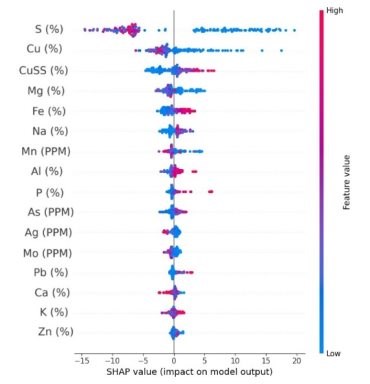
|
As an additional example, the selected talc model, the SHAP analysis indicates that magnesium is the dominant predictor, with higher Mg values generally associated with increased predicted talc content. The Mg-Ca interaction provides an important secondary control, while the remaining geochemical and spatial variables have comparatively smaller effects. This response is consistent with the Mg-rich geochemical character of talc-bearing material and supports the geological reasonableness of the selected model. The SHAP response for the selected talc model is illustrated in Figure 14-14.
Figure 14-14: Shap Summary Plot for the Selected Random Forest Talc Model
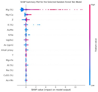
Overall, the SHAP analysis indicates that the better-performing models are responding to coherent geochemical patterns rather than arbitrary statistical relationships.
Systematic visual validation was also conducted by comparing the predicted block model values with the corresponding TIMA sample observations on representative cross sections through the East Deposit. The review considered the local agreement between observed and predicted mineral abundances, the continuity of the predicted response between sample locations, and the behavior of the model near the limits of the mineralized domains. Overall, the sections show that the model reproduces the main spatial patterns present in the TIMA data, while local differences occur mainly in areas with limited sample support and near transitional or hard-domain boundaries. Representative validation sections for primary copper sulfides, secondary copper sulfides, copper carbonates, copper wads, and talc are presented in Figure 14-15 to Figure 14-19.
|
Figure 14-15: Representative Validation Cross Section Comparing the Predicted Primary Copper Sulfide Distribution with the Corresponding Tima Observations in the East Deposit
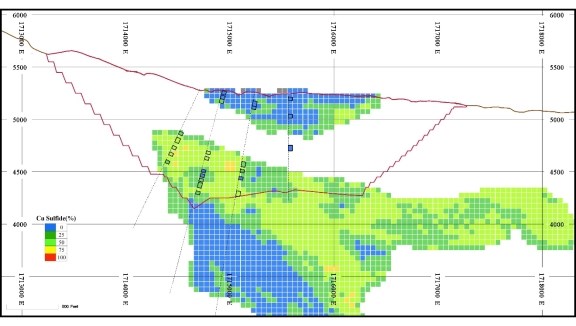
Figure 14-16: Representative Validation Cross Section Comparing the Predicted Secondary Copper Sulfide Distribution with the Corresponding Tima Observations in the East Deposit
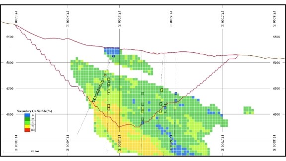
|
Figure 14-17: Representative Validation Cross Section Comparing the Predicted Copper Goethite Distribution with the Corresponding Tima Observations in the East Deposit
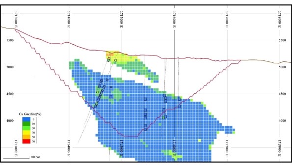
Figure 14-18: Representative Validation Cross Section Comparing the Predicted Copper WADS Distribution with the Corresponding Tima Observations in the East Deposit
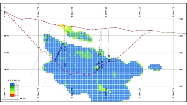
|
Figure 14-19: Representative Validation Cross Section Comparing the Predicted Talc Abundance in the Block Model with the Corresponding Tima Observations in the East Deposit
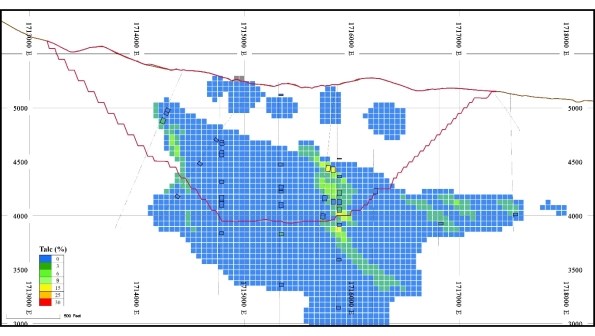
14.16 Classification of Mineral Resource
During the interpolation process, several control parameters were recorded for each block. These included the number of samples, number of holes, the distance to the nearest sample, and the average distance to all the samples used for the interpolation, as well as the number of quadrants with samples, the kriging variance, and the regression slope of kriging for each individual block estimate.
The regression slope values obtained from the kriging of copper and soluble copper grade estimates were used as the primary criteria for resource classification with 80% and 60% regression slope thresholds respectively used to separate "Measured" from "Indicated" and "Inferred" resources. From detailed reserves to mill reconciliations exercises conducted by Hudbay at its operating mines, these criteria were found to be a reliable first pass measure of quarterly and annual performance in tonnes and grade prediction.
The block-by-block coding assignation was then smoothed to remove isolated blocks of one category within another. Globally, proportions of "Measured", "Indicated" and "Inferred" category blocks were not changed significantly by this process. Figure 14-20 illustrates the classification before and after smoothing, while Table 14-14 presents the classification proportion before and after smoothing.
In some portions of the Peach-Elgin and Broadtop Butte deposits, skarn mineralization occurs as a thin, undulating shape wrapping around a porphyry, and as such, using a traditional search in a Cartesian coordinates reference system has most blocks classified as inferred based on the kriging slope of regression, while drilling density is similar to areas classified as indicated elsewhere in the same deposit. Hudbay worked jointly with WSP to confirm that the use of unfolding in such mineralized areas with an undulating shape would result in an improved kriging slope of regression without altering the mineral resource estimates. Based on the work conducted, and the drilling density in this area, there is a higher level of confidence in the resource model than initially indicated by the slope of regression without the use of unfolding, and as a result the resource classification was locally upgraded from inferred to indicated. Hudbay intends to perform grade interpolation using an unfolding algorithm in future updates of the resource model for areas with an undulating mineralized envelope.
|
Figure 14-20: WSP Model of Skarn Mineralization & Composites Broadtop Butte Zone - Plan View
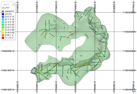
Table 14-14: Resource Classification Proportion Pre & Post Processing
| Classification | Block by Block | Smoothed |
| Measured | 58.4% | 56.3% |
| Indicated | 13.3% | 22.3% |
| Inferred | 28.3% | 21.4% |
|
Figure 14-21: Resource Classification of the Copper World Project Deposits
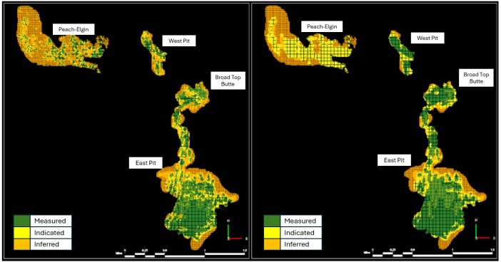
14.17 Reasonable Prospects for Economic Extraction & Mineral Resource Estimates
The component of the mineralization within the block model that meets the requirements for reasonable prospects of economic extraction was based on the application of the Lerchs-Grossman algorithm. The mineral resources are therefore contained within a computer-generated open pit geometry.
Table 14-15: Mineral Resource Statement (Inclusive of Mineral Reserves)
| Category | Metric Tonnes | Short Tons | Cu | Mo | Ag | Au | |
| (in million) | (in million) | (%) | (ppm) | (ppm) | (ppm) | ||
| INCLUSIVE | Measured | 889.5 | 980.5 | 0.42 | 124 | 4.43 | 0.022 |
| Indicated | 346.5 | 382.0 | 0.35 | 109 | 3.32 | 0.015 | |
| M+I | 1,236.0 | 1,362.5 | 0.40 | 120 | 4.12 | 0.020 | |
| Inferred | 309.3 | 341.0 | 0.30 | 103 | 2.69 | 0.012 |
Notes: 1. CIM Definition Standards (2014) were used for reporting the Mineral Resources. 2. Numbers may not compute exactly due to rounding. 3. The Qualified Person is Olivier Tavchandjian. 4. Mineral Resources are estimated as of 1st August 2026. 5. An NSR cut-off value of $6.03/st. was used to define material as ore. 6. Mineral resource estimates are inclusive of mineral reserves and have been tested using pit optimization software with the following assumptions: metal prices of US$5.00/lb Cu, US$20.00/lb Mo, US$3,600/oz Au, and US$50.00/ oz Ag; operating costs of US$1.61/st, US$5.34/st processed, G&A costs of US$0.69/st processed; metallurgical recovery rates vary according to elemental content, and are based on preliminary metallurgical test work. 7. Mineral resources are not mineral reserves as they do not have demonstrated economic viability.
|
Table 14-16 summarizes the mineral resource estimates exclusive of the measured and indicated mineral resources that were converted to mineral reserve estimates. These mineral resource estimates include resource estimates in all categories located inside a pit shell with revenue factor of 1.0 and outside of the mineral reserve pit, as well as mineral resource estimates located within the mineral reserve pit but not processed within the mine life of the Base Case presented in the Definitive Feasibility Study and as such excluded from the mineral reserve estimates but still deemed to have potential for economic extraction with additional infill drilling and/or additional metallurgical test work and/or permitting certainty.
Table 14-16: Mineral Resource Statement (Exclusive of Mineral Reserves)
| Category | Metric Tonnes | Short Tons | Cu | Mo | Ag | Au | |
| (in million) | (in million) | (%) | (ppm) | (ppm) | (ppm) | ||
| EXCLUSIVE | Measured | 559.5 | 616.8 | 0.40 | 135 | 3.94 | 0.021 |
| Indicated | 286.1 | 315.4 | 0.33 | 112 | 3.15 | 0.015 | |
| M+I | 845.7 | 932.2 | 0.37 | 127 | 3.68 | 0.019 | |
| Inferred | 309.3 | 341.0 | 0.30 | 103 | 2.69 | 0.012 |
Notes: 1. CIM Definition Standards (2014) were used for reporting the Mineral Resources. 2. Numbers may not compute exactly due to rounding. 3. The Qualified Person is Olivier Tavchandjian. 4. Mineral Resources are estimated as of 1st August 2026. 5. An NSR cut-off value of $6.03/st. was used to define material as ore. 6. Mineral resource estimates are exclusive of mineral reserves and have been tested using pit optimization software with the following assumptions: metal prices of US$5.00/lb Cu, US$20.00/lb Mo, US$3,600/oz Au, and US$50.00/ oz Ag; operating costs of US$1.61/st, US$5.34/st processed, G&A costs of US$0.69/st processed; metallurgical recovery rates vary according to elemental content, and are based on preliminary metallurgical test work. 7. Mineral resources are not mineral reserves as they do not have demonstrated economic viability.
Table 14-17 presents a comparison of the mineral resource estimates (inclusive of mineral reserve estimates) presented in the 2023 PFS and the 2026 Definitive Feasibility Study mineral resource estimates. The mineral resource estimates provided in the 2023 PFS have been superseded by those presented in this Technical Report as part of the 2026 Definitive Feasibility Study. Overall, the changes between the 2023 and 2026 mineral resource estimates inclusive of the mineral reserve estimates are essentially a function of the changes in the technical and economic criteria used to report resources, i.e., use of a NSR cut-off replacing a copper cut-off, use of a new flotation recovery formulation and removal of the leachable mineral resource estimates.
Table 14-17: Comparison of 2023 vs 2026 Mineral Resource Estimates
| Category | 2023 PFS | 2026 FS | Delta | ||||
| Million Tonnes | %Cu | Contained Cu Tonnes | Million Tonnes | %Cu | Contained Cu Tonnes | ||
| Measured + Indicated | 1,205 | 0.42 | 5,061,000 | 1,236 | 0.40 | 4,993,440 | -1% |
| Inferred | 275 | 0.32 | 880,000 | 309 | 0.30 | 927,000 | 5% |
Note: 1. Totals may not add up correctly due to rounding.
14.18 Conclusion
The mineral resource estimation is well-constrained by three-dimensional wireframes representing geologically realistic volumes of mineralization. Exploratory data analysis has demonstrated that the wireframes are suitable domains for mineral resource estimation. Grade estimation has been performed using an interpolation plan designed to minimize bias, and over-smoothing has been addressed to estimate the correct tonnes and grades of the deposits.
|
Mineral resources are constrained and reported using economic and technical criteria such that the mineral resource has reasonable prospects of economic extraction. In particular, the addition of a robust process to predict the deportment of copper amongst 7 group of minerals, the distribution of swelling clays and abundance of pyrite in the flotation concentrate has considerably improved the estimation of recoverable metal as well as providing useful indicators to optimize future mill feed blending requirements. The estimated mineral resources for the Project conform to the requirements of 2014 CIM Definition Standards for Mineral Resources and Mineral Reserves (CIM, 2014), and requirements in Form 43-101F1 of NI 43-101, Standards of Disclosure for Mineral Projects (CIM, 2011).
|
15 MINERAL RESERVE ESTIMATE
15.1 Methodology
Mineral Resources are converted to Mineral Reserves primarily by demonstrating economic viability through a comprehensive engineering assessment and consideration of other modifying factors that could affect economic viability. This assessment involves pit optimization, pit design, equipment selection, production scheduling, and economic evaluation. In accordance with CIM Definition Standards, Mineral Reserves are only estimated based on Measured and Indicated Mineral Resources. Inferred Mineral Resources are treated as waste for the purpose of pit optimization, mine planning, and economic evaluation.
The mine planning work was conducted using only measured and indicated mineral resource estimates for a base case limited to the perimeter of the project currently permitted for mining and waste and tailings deposition. To ensure compliance with the requirement for reasonable prospects of eventual economic extraction and current permitting status, only the base case mine plan was used to estimate Mineral Reserves.
To convert Mineral Resources to Mineral Reserves, the following process was applied for mine planning and is described in further detail in Section 16 (Mining Methods):
• Economic Parameters: Determination of an economic cut-off grade [Net Smelter Return] based on projected mining and processing operating costs, metallurgical recoveries, and metal prices. The economic parameters and assumptions used for preparing the mineral reserve and mineral resource estimates in this Technical Report (which are estimated as of August 1, 2026) may differ from the economic parameters and assumptions used elsewhere in this Technical Report for purposes of the economic evaluation of the Project. Please refer to the applicable estimates and assumptions provided throughout this Technical Report.
• Modifying Factors: Application of mining dilution and mining recovery parameters to the geological resource block model to create a regularized mining block model.
• Pit Optimization: Definition of ultimate pit limits and internal mining phases (pit shells) using the Lerchs-Grossmann (LG) algorithm as implemented in GEOVIA Whittle 2022 software.
• Pit Design: Development of detailed, engineered pit designs from the selected optimal pit limits. These designs incorporate geotechnical parameters (e.g., bench angles, berm widths) and practical mining constraints (e.g., minimum mining widths, access ramps).
• Mine Scheduling: Creation of a life-of-mine (LOM) production schedule that dictates waste stripping, mill feed, and product generation, constrained by equipment productivities and processing throughput capacities.
• Costing and Economic Viability: Estimation of capital and operating costs based on the scheduled LOM plan, culminating in a discounted cash flow analysis (detailed in Sections 21 & 22) to demonstrate the economic viability of the mineral reserve estimates.
|
The Measured and Indicated Mineral Resources located outside the exterior boundary of Copper World's Patented Claims have been excluded from the Mineral Reserve statement.
Section 24 details an Extension Case - an extended Life of Mine (LOM) scenario- that incorporates conceptual mining plans beyond current tenement limits.
15.2 Pit Optimization and Mine Design Basis
15.2.1 Pit Optimization
Open-pit optimizations were conducted using the Lerch-Grossmann (LG) algorithm in GEOVIA Whittle 2022 software. To evaluate the overall economic potential of the Project's four deposits, an initial combined optimization was performed to establish an indicative mining sequence that accounted for shared processing plant and waste deposition constraints. Subsequently, individual optimizations were executed for each deposit to improve local pit definition and support the development of higher-resolution ultimate pit limits and phased designs.
These results were evaluated on a pit-by-pit (nested shell) basis, generating ore and waste inventories alongside indicative discounted cash flow estimates for "best-case" and "worst-case" mining sequences:
• Best-Case Scenario: Assumes sequential mining from the smallest internal shell to the largest external shell, yielding the maximum indicative discounted value. In practice, this scenario is rarely achievable because the pushback widths between consecutive nested shells are typically too narrow to accommodate safe and efficient mining equipment operation.
• Worst-Case Scenario: Assumes the ultimate pit shell is mined continuously on a flat, bench-by-bench basis (top-down) rather than by incremental phases. This delays access to deeper ore, yielding the lowest indicative discounted value.
Several optimization iterations were completed to assess the sensitivity of the pit shells to key modifying factors and updated inputs. These iterations were primarily utilized to:
• Quantify the impact of incremental changes to the Net Smelter Return (NSR) model.
• Generate a spectrum of optimized nested shells to guide the selection of the ultimate pit limit and intermediate pushbacks (phases).
• Update in-pit tonnage and grade curves to refine the life-of-mine stockpiling strategy.
• Evaluate the spatial impact of incorporating haul road allowances within various wall sectors of the ultimate pit to finalize the access design strategy.
To generate the optimal pit geometry, which serves as the foundational basis for detailed mine design, the optimization process incorporated the following key parameters:
• Geotechnical Constraints: Wall slope angles by defined geotechnical domains.
|
• Spatial Constraints: Perimeter of the exterior boundary of Copper World's Patented Claims, bench heights, and minimum mining widths.
• Economic Criteria: Anticipated metal prices, mining costs, processing costs, and General & Administrative (G&A) expenses.
• Operational Factors: Metallurgical recoveries, mining recovery, and expected mining dilution.
It should be noted that the Net Present Value (NPV) estimates generated during this pit optimization work are indicative only and exclude capital costs. The specific inputs and assumptions utilized in this process are detailed further in the subsequent sections of this report. Section 22 (Economic Analysis) provides the definitive, fully modelled project cash flow and NPV estimates. Table 15-1 and Figure 15-1 illustrates the process followed for the combined deposits.
Table 15-1: Combined Deposit Pit Optimization
| LG Shells | Total Millfeed | Material | |||||||||
| Pit | RevFac | Life | Mill Feed | NSR | Cu | Mo | Au | Ag | Waste | Strip R | Total |
| (#) | (yrs) | M st | $/st | % | ppm | ppm | ppm | M st | (w:o) | M st | |
| Pit 1 | 0.04 | 0.0 | 0.0 | 340.36 | 0.244 | 24 | 0.009 | 2.3 | 0.0 | 0.0 | 0.0 |
| Pit 2 | 0.08 | 0.0 | 0.1 | 113.33 | 2.314 | 58 | 0.009 | 15.4 | 0.0 | 0.0 | 0.1 |
| Pit 3 | 0.10 | 0.0 | 0.4 | 95.08 | 1.868 | 85 | 0.026 | 11.8 | 0.1 | 0.1 | 0.4 |
| Pit 4 | 0.12 | 0.0 | 1.3 | 80.26 | 1.439 | 135 | 0.042 | 11.5 | 0.4 | 0.3 | 1.7 |
| Pit 5 | 0.14 | 0.1 | 4.6 | 70.48 | 1.217 | 240 | 0.028 | 6.9 | 2.6 | 0.6 | 7.2 |
| Pit 6 | 0.16 | 0.2 | 7.9 | 64.73 | 1.125 | 234 | 0.024 | 6.1 | 4.4 | 0.6 | 12.3 |
| Pit 7 | 0.18 | 0.4 | 11.6 | 61.33 | 1.050 | 223 | 0.022 | 5.5 | 8.2 | 0.7 | 19.8 |
| Pit 8 | 0.20 | 1.3 | 41.3 | 67.90 | 1.049 | 163 | 0.030 | 8.8 | 106.6 | 2.6 | 147.9 |
| Pit 9 | 0.22 | 1.6 | 52.2 | 63.41 | 0.986 | 161 | 0.030 | 8.3 | 120.4 | 2.3 | 172.6 |
| Pit 10 | 0.24 | 2.0 | 64.4 | 58.86 | 0.915 | 156 | 0.030 | 8.0 | 131.1 | 2.0 | 195.4 |
| Pit 11 | 0.26 | 2.3 | 76.3 | 55.51 | 0.870 | 153 | 0.029 | 7.7 | 143.4 | 1.9 | 219.7 |
| Pit 12 | 0.28 | 2.9 | 94.4 | 51.50 | 0.812 | 144 | 0.029 | 7.1 | 163.0 | 1.7 | 257.4 |
| Pit 13 | 0.30 | 6.3 | 207.3 | 45.54 | 0.686 | 124 | 0.032 | 7.1 | 429.7 | 2.1 | 637.0 |
| Pit 14 | 0.32 | 7.5 | 246.4 | 43.69 | 0.661 | 121 | 0.031 | 6.7 | 499.1 | 2.0 | 745.5 |
| Pit 15 | 0.34 | 8.8 | 289.5 | 41.74 | 0.639 | 116 | 0.030 | 6.4 | 558.6 | 1.9 | 848.1 |
| Pit 16 | 0.36 | 9.7 | 317.1 | 40.51 | 0.620 | 116 | 0.029 | 6.1 | 593.9 | 1.9 | 910.9 |
| Pit 17 | 0.38 | 10.2 | 334.3 | 39.63 | 0.608 | 115 | 0.028 | 6.0 | 604.7 | 1.8 | 939.1 |
| Pit 18 | 0.40 | 10.7 | 349.9 | 38.74 | 0.596 | 114 | 0.028 | 5.9 | 605.5 | 1.7 | 955.4 |
| Pit 19 | 0.42 | 11.0 | 362.3 | 38.00 | 0.586 | 113 | 0.027 | 5.8 | 601.4 | 1.7 | 963.6 |
| Pit 20 | 0.44 | 11.5 | 377.5 | 37.22 | 0.575 | 113 | 0.026 | 5.7 | 605.8 | 1.6 | 983.3 |
| Pit 21 | 0.46 | 12.3 | 404.4 | 36.70 | 0.567 | 114 | 0.026 | 5.6 | 699.0 | 1.7 | 1,103.4 |
| Pit 22 | 0.48 | 12.7 | 417.3 | 36.11 | 0.559 | 113 | 0.026 | 5.5 | 703.7 | 1.7 | 1,121.0 |
| Pit 23 | 0.50 | 13.2 | 432.2 | 35.51 | 0.552 | 113 | 0.025 | 5.4 | 718.9 | 1.7 | 1,151.1 |
|
| LG Shells | Total Millfeed | Material | |||||||||
| Pit | RevFac | Life | Mill Feed | NSR | Cu | Mo | Au | Ag | Waste | Strip R | Total |
| (#) | (yrs) | M st | $/st | % | ppm | ppm | ppm | M st | (w:o) | M st | |
| Pit 24 | 0.52 | 13.5 | 443.2 | 34.99 | 0.545 | 112 | 0.025 | 5.4 | 717.3 | 1.6 | 1,160.5 |
| Pit 25 | 0.54 | 13.8 | 454.3 | 34.47 | 0.537 | 111 | 0.024 | 5.3 | 716.8 | 1.6 | 1,171.1 |
| Pit 26 | 0.56 | 14.2 | 465.8 | 33.96 | 0.530 | 111 | 0.024 | 5.3 | 716.2 | 1.5 | 1,182.0 |
| Pit 27 | 0.58 | 14.5 | 475.6 | 33.52 | 0.524 | 110 | 0.024 | 5.2 | 715.2 | 1.5 | 1,190.8 |
| Pit 28 | 0.60 | 14.8 | 484.9 | 33.11 | 0.519 | 109 | 0.024 | 5.2 | 713.3 | 1.5 | 1,198.2 |
| Pit 29 | 0.62 | 15.1 | 495.1 | 32.67 | 0.513 | 108 | 0.023 | 5.1 | 711.4 | 1.4 | 1,206.6 |
| Pit 30 | 0.64 | 15.3 | 503.6 | 32.30 | 0.507 | 108 | 0.023 | 5.1 | 707.9 | 1.4 | 1,211.5 |
| Pit 31 | 0.66 | 15.6 | 513.1 | 31.92 | 0.502 | 107 | 0.023 | 5.0 | 708.7 | 1.4 | 1,221.9 |
| Pit 32 | 0.68 | 15.9 | 522.6 | 31.54 | 0.497 | 106 | 0.023 | 5.0 | 708.9 | 1.4 | 1,231.5 |
| Pit 33 | 0.70 | 16.2 | 532.2 | 31.20 | 0.492 | 105 | 0.023 | 4.9 | 714.3 | 1.3 | 1,246.5 |
| Pit 34 | 0.72 | 16.5 | 540.5 | 30.88 | 0.488 | 105 | 0.022 | 4.9 | 715.1 | 1.3 | 1,255.6 |
| Pit 35 | 0.74 | 16.7 | 548.0 | 30.60 | 0.484 | 104 | 0.022 | 4.9 | 714.4 | 1.3 | 1,262.4 |
| Pit 36 | 0.76 | 16.9 | 554.9 | 30.34 | 0.480 | 104 | 0.022 | 4.8 | 713.7 | 1.3 | 1,268.6 |
| Pit 37 | 0.78 | 17.1 | 562.4 | 30.06 | 0.476 | 103 | 0.022 | 4.8 | 712.3 | 1.3 | 1,274.7 |
| Pit 38 | 0.80 | 17.3 | 568.5 | 29.83 | 0.473 | 103 | 0.022 | 4.8 | 710.0 | 1.2 | 1,278.5 |
| Pit 39 | 0.82 | 17.5 | 574.6 | 29.60 | 0.469 | 102 | 0.022 | 4.7 | 706.7 | 1.2 | 1,281.3 |
| Pit 40 | 0.84 | 17.7 | 580.1 | 29.40 | 0.466 | 102 | 0.022 | 4.7 | 703.7 | 1.2 | 1,283.8 |
| Pit 41 | 0.86 | 17.9 | 586.5 | 29.17 | 0.463 | 101 | 0.021 | 4.7 | 702.4 | 1.2 | 1,288.9 |
| Pit 42 | 0.88 | 18.0 | 591.7 | 28.98 | 0.461 | 101 | 0.021 | 4.7 | 701.6 | 1.2 | 1,293.3 |
| Pit 43 | 0.90 | 18.2 | 598.2 | 28.76 | 0.457 | 100 | 0.021 | 4.6 | 701.8 | 1.2 | 1,300.0 |
| Pit 44 | 0.92 | 18.4 | 604.4 | 28.55 | 0.454 | 100 | 0.021 | 4.6 | 701.5 | 1.2 | 1,305.9 |
| Pit 45 | 0.94 | 18.6 | 609.7 | 28.37 | 0.451 | 100 | 0.021 | 4.6 | 700.5 | 1.1 | 1,310.2 |
| Pit 46 | 0.96 | 18.7 | 614.2 | 28.22 | 0.449 | 99 | 0.021 | 4.6 | 699.2 | 1.1 | 1,313.3 |
| Pit 47 | 0.98 | 18.9 | 619.3 | 28.05 | 0.447 | 99 | 0.021 | 4.6 | 701.1 | 1.1 | 1,320.4 |
| Pit 48 | 1.00 | 19.2 | 630.0 | 27.74 | 0.442 | 99 | 0.021 | 4.5 | 714.2 | 1.1 | 1,344.1 |
| Pit 49 | 1.02 | 19.3 | 635.2 | 27.58 | 0.440 | 98 | 0.020 | 4.5 | 718.0 | 1.1 | 1,353.3 |
| Pit 50 | 1.04 | 19.5 | 639.4 | 27.45 | 0.438 | 98 | 0.020 | 4.5 | 716.6 | 1.1 | 1,356.0 |
| Pit 51 | 1.06 | 19.6 | 644.1 | 27.30 | 0.436 | 98 | 0.020 | 4.5 | 718.0 | 1.1 | 1,362.1 |
| Pit 52 | 1.08 | 19.7 | 647.8 | 27.18 | 0.434 | 97 | 0.020 | 4.4 | 716.9 | 1.1 | 1,364.7 |
| Pit 53 | 1.10 | 19.9 | 652.2 | 27.05 | 0.432 | 97 | 0.020 | 4.4 | 716.1 | 1.1 | 1,368.3 |
| Pit 54 | 1.12 | 20.0 | 656.3 | 26.91 | 0.430 | 97 | 0.020 | 4.4 | 714.2 | 1.1 | 1,370.5 |
| Pit 55 | 1.14 | 20.1 | 660.1 | 26.79 | 0.428 | 96 | 0.020 | 4.4 | 713.2 | 1.1 | 1,373.3 |
| Pit 56 | 1.16 | 20.2 | 663.6 | 26.69 | 0.427 | 96 | 0.020 | 4.4 | 712.3 | 1.1 | 1,375.9 |
| Pit 57 | 1.18 | 20.3 | 668.4 | 26.54 | 0.424 | 96 | 0.020 | 4.4 | 712.9 | 1.1 | 1,381.3 |
| Pit 58 | 1.20 | 20.5 | 672.1 | 26.43 | 0.423 | 96 | 0.020 | 4.3 | 712.3 | 1.1 | 1,384.4 |
|
Figure 15-1: Pit-by-pit results for the Combined Pits Optimization
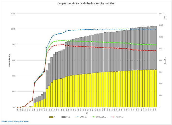
As noted in Figure 15-1, the Pit-by-Pit curve assumes mining the most profitable nested shells first. It rises sharply and plateaus around RF 0.46 to 0.50, slowly approaching 100%. The initial Shells (RF 0.04 to 0.28) are very small, capturing high-grade, near-surface ore with minimal waste stripping. There is a rapid expansion (RF 0.30 to 0.46) in both Ore (yellow) and Waste (grey) tonnages. This represents the main orebody being captured as the simulated price increases enough to justify the required waste stripping. Beyond RF 0.46, the pit continues to grow, but the proportion of waste to ore (the strip ratio) noticeably increases. The yellow ore bars grow at a much slower rate than the overall pit size.
Representing a practical mining schedule utilizing defined phases/pushbacks, the green line closely tracks the "Best" economic case initially but peaks around RF 0.46 to 0.48. After this point, adding larger shells marginally diminishes the value (NPV).
|
15.2.2 Ultimate Pit Limits selection
For the Base Case economic scenario, ultimate pit limit shells were selected to maximize resource extraction within available processing capacities without compromising incremental economic returns. These selections strictly adhere to the spatial constraints imposed by the current permits. This methodology achieves an optimal balance between resource recovery and operational practicality, providing a robust foundation for subsequent detailed mine design and life-of-mine (LOM) production scheduling (Figure 15-2).
Figure 15-2: Plan view of Lerchs-Grossmann Pit (RF=1 shell) representing the maximum economical pit size at strategic planning level- the purple outline represents the exterior boundary of Copper World's Patented Claims
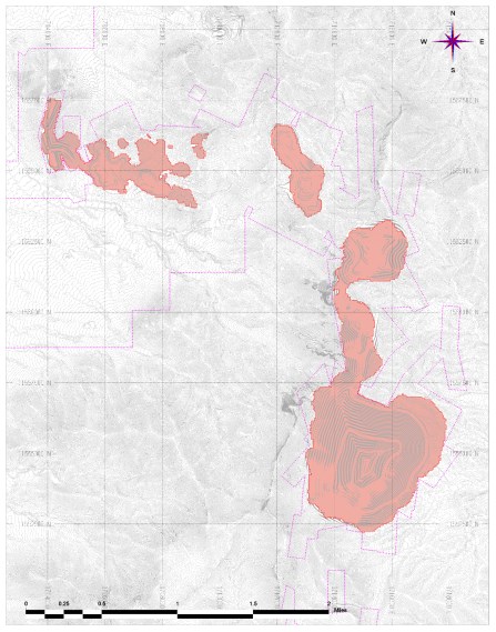
|
15.2.3 Mine Design Parameters
Open pit design parameters are driven by the project's mine operating strategy, equipment selection, and strict pit stability criteria. To constrain pushback sequencing and ensure achievable production targets, the vertical advance rate is capped at 10 benches per year. Additionally, haul road widths are optimized to minimize stripping ratios without compromising the safety of staffed or Autonomous Haulage System (AHS) operations.
15.2.3.1 Geometric Parameters
• Bench Height: 50 ft, applied consistently across all pits and mining phases, optimized for 320-t truck productivity and matched shovel capacities within geotechnical constraints.
• Vertical Advance Rate: Constrained to a maximum of 500 ft per year (equivalent to ten benches) to ensure pushback sequencing remains operationally achievable and safe.
• Slope Guidance: Detailed pit slope design parameters by geotechnical domain are summarized in Section 16.1.5.
• Property Constraints: Optimizations and pit designs incorporate an internal setback from the exterior boundary of Copper World's Patented Claims. The preliminary recommended boundary offsets, provided by Knight Piésold (KP), are detailed in Table 15-2.
Table 15-2: Preliminary Recommended Offsets from Property Boundaries
| Material Type | Buffer from Property Limits to Pit Crest (ft) | Comments |
| Competent/Rock | 25 | 1:1 slope of height of 1st bench. Mine 1/2 bench for 1st bench |
| Loose/Ovb | 75 | 3:1 slope of height of 1st bench. Mine 1/2 bench for 1st bench (East & South of East Pit) |
Road widths are selected to minimize stripping ratios while maintaining safe operations for both staffed and Autonomous Haulage System (AHS).
15.2.3.2 In-Pit Crushing & Conveying (IPCC)
The In-Pit Crushing and Conveying (IPCC) system forms a critical component of the mine plan to efficiently manage the high material tonnages commencing in Year 5 and beyond.
• East Pit Deployment: The IPCC system becomes operational in Year 4 to convey ore from the East Pit to stockpiles and the processing plant.
• Location: The IPCC system is located at the south end of the Broad Top Phase 3 pit and is not scheduled for relocation.
The IPCC system is designed with a nominal capacity of 100 kstpd.
|
15.3 Block Model
The Mineral Reserve block model (MEBM) is based on the Mineral Resource block model (MRBM) described in Section 14. To reflect anticipated mining practices and account for potential ore dilution from internal waste, the MRBM was regularized to Selective Mining Unit (SMU) dimensions of 50 ft × 50 ft × 50 ft.
Diluted mineral grades for Cu, Mo, Au, and Ag, along with Zn, Fe, Mg, Ca, As, S, and other relevant elements, were directly imported from the resource block model. Control attributes, including alteration, oxidation state, and acid potential ratios, were also retained.
An economic evaluation was then performed to compute a Net Smelter Return (NSR) value for each block (expressed in US$/st). This calculation incorporated the diluted grades, metallurgical recoveries, smelting and refining terms (including payables and deductions), and commodity prices for copper (Cu), molybdenum (Mo), gold (Au), and silver (Ag).
15.3.1 Metallurgical Recoveries
The metallurgical recovery presented in Section 13 was used to populate the NSR attribute in the mine engineering block model.
Because a diverse set of samples across multiple test programs was used to develop this model, maintaining a fixed concentrate grade target was unfeasible; the resulting concentrate grade varies as a function of feed mineralogy.
To maintain metallurgical performance in the mill, the following constraints are placed on the mill feed plan:
• Primary + Secondary Cu Sulfide Content (> 70 %)
• Talc Concentration (< 1.5 % Target, < 2 % Cap)
• Pyrite Concentration (< 1.5 % Target, < 2 % Cap)
• Swelling Clay (< 3.5 % Target, < 4.5 Cap)
• Total Clay Mineralization (< 11% Target, < 14 % Cap)
• Total Cu Sulfide Grade 
15.3.2 Economic Parameters
Revenue from production was estimated on the basis that ores will be treated on site to produce copper and molybdenum concentrates to be sold off-site. The concentrates contain payable amounts of gold and silver as well.
For the purpose of preparing a pit optimization and mine plan, revenue potential was estimated in US dollars per Ton ($/st) as an NSR value accounting for the following items:
• Metal selling price.
|
• Metallurgical recovery rates.
• Royalties payable on revenue.
• Off-site transportation costs.
• Concentrate specifications.
• Commercial terms of the buyer/smelter.
Metal prices, Foreign Exchange, and royalty rates used in the NSR calculation are presented in Table 15-3. These values were used as conservative forecast prices and are only used for the NSR calculation.
Table 15-3: Metal Pricing Assumptions
| Item | Unit | Value |
| Price - Cu | US$/lb | $5.00 |
| Price - Mo | US$/lb | $20.00 |
| Price - Au | US$/oz | $3,600 |
| Price - Ag | US$/oz | $50.00 |
| Royalties | % of NSR | 3.00% |
Off-site costs, concentrate specifications, and commercial terms used to estimate the value of concentrate products are presented in for the copper concentrate, and for the molybdenum concentrate. Like metal prices, these values shift over time and may change in the future.
Table 15-4: Copper Concentrate Specification and Commercial Terms
| Copper Concentrate | Units | Value |
| Concentrate Grade | % Cu | 30 |
| Treatment cost Cu | $/dst Cu con | 49.895 |
| Refining cost of Cu | $ / payable lb - Cu | 0.055 |
| Refining cost of Ag | $ / payable oz Ag | 0.50 |
| Refining cost of Au | $ / payable oz - Au | 5.00 |
| Payable of Cu | % | 96.5 |
| Minimum deduction in Cu | % Cu | 1.0 |
| Payable of Ag | % | 90.0 |
| Minimum Grade Ag | oz/dst | 0.029 |
| Payable of Au | % | 90.0 |
| Minimum Grade Au | oz/dst | 0.875 |
| Freight | $ / wst Cu con | 152.41 |
| Moisture content | % Cu con | 8.0 |
Table 15-5: Molybdenum Concentrate Specifications and Commercial Terms
| Molybdenum Concentrate | Units | Value |
| Concentrate Grade | % Mo | 50 |
|
| Molybdenum Concentrate | Units | Value |
| Treatment cost Mo | $ /lb Mo con | 1.300 |
| Payable of Mo | % | 99.0 |
| Freight | $ / wst Mo con | 18.144 |
| Moisture content | % Mo con | 6.0 |
15.3.3 Cut-Off Grade
The economic cut-off value is calculated based on NSR basis and is estimated at $5.80 per ton of ore processed (excluding mining). Operating cost assumptions used on pit optimizations and the determination of ultimate pit limits are shown in Table 15-6 below.
Table 15-6: Operating Cost
| Area | Unit | |
| Mining Cost | US$/st | $ 1.74 |
| Processing Cost | US$/st processed | $ 5.07 |
| General & Administrative cost | US$/st processed | $ 0.73 |
15.4 Mineral Reserves
Mineral Reserves estimates are derived from Measured and Indicated resources. Inferred resources within the ultimate pit are classified as waste, as they do not currently satisfy the economic and mining criteria required for reserve classification.
15.4.1 Mineral Reserve Definition Parameters
The Base Case commodity prices and operating cost assumptions presented in Section 15.2.2 and 15.2.3 are used to define the economic mining limits for the estimation of mineral reserves.
15.4.2 Material Densities
Bulk material densities, varying by rock type, were sources from the resource block model as described in Section 14. Rock tonnage factors range from 11.7 ft3/ton to 12.4 ft3/ton, with an average of 12.10 ft3/ton for material within the ultimate pit limits.
15.4.3 Ore loss and Dilution
The regularization of the Resource Block Model introduces internal dilution into the Mineral Reserve block model. Given the spatial continuity and distribution of the ore blocks, it has been assessed that this internal dilution fully accounts for both anticipated mining dilution and ore loss. Consequently, no additional modifying factors have been applied.
|
15.4.4 Mineral Reserves Statement
The Mineral Reserves represent the economically mineable part of Measured and Indicated Mineral Resources (see Section 14). Measured Resources have been converted to Proven Reserves and Indicated Resources to Probable Reserves. As described above, Mineral Resources have been converted to Mineral Reserves after conducting the following key steps:
• Re-blocking
• Assigning economic values to blocks
• Pit limits optimization
• Mine design
Mine scheduling, operating costs, and economic estimates were evaluated using a set of optimized mining phases, successfully demonstrating positive economics. These elements are discussed in further detail in Section 16.
To verify reasonable prospects for eventual economic extraction, pit optimizations were conducted assuming open-pit mining and the on-site production of separate copper and molybdenum concentrates. The optimization software incorporated the following parameters:
• Metal Prices: US$5.00/lb Cu, US$20.00/lb Mo, US$3,600/oz Au, and US$50.00/oz Ag.
• Operating Costs: US$1.74/st (mining), US$5.07/st (processing), and US$0.73/st (G&A).
• Metallurgical Recoveries: Variable based on elemental content, derived from preliminary metallurgical test work.
The total ore processing capacity of the project is currently constrained by the Tailings Storage Facility (TSF), which has an estimated capacity of 443.2 million short tons (Mst). To define material as ore, a base Net Smelter Return (NSR) cut-off value of US$5.80/st was applied. Furthermore, to optimize the limited TSF capacity a minimum Cu grade of 0.1% and a minimum Cu recovery of 48% were established as additional constraints.
A small portion of material with an NSR above US$5.80/st that did not meet the minimum Cu grade or recovery thresholds was processed to blend with higher-grade, higher-recovery ore. The remainder of this material was placed in stockpiles, available for potential future reclaim, provided that future TSF capacity expansions and project economics warrant it.
Table 15-7: Proven & Probable Mineral Reserves Total
| Category | Metric Tonnes (in million) |
Short Tons (in million) |
Cu (%) |
Mo (ppm) |
Ag (ppm) |
Au (ppm) |
| Proven | 330.0 | 363.7 | 0.47 | 105 | 5.25 | 0.024 |
| Probable | 60.4 | 66.6 | 0.46 | 94 | 4.14 | 0.018 |
| Total | 390.4 | 430.3 | 0.47 | 103 | 5.08 | 0.023 |
Notes: 1. CIM Definition Standards (2014) were used for reporting the Mineral Reserves. 2. Numbers may not compute exactly due to rounding. 3. The Qualified Person is Olivier Tavchandjian. 3. Mineral Reserves are estimated as of 1st August 2026. 4. Probable Mineral Reserves are based on Indicated Mineral Resources only. 5. Proven Mineral Reserves are based on Measured Mineral Resources only. 6. Mineral Reserve estimates are limited to the portion of the Measured and Indicated Resource estimates scheduled for milling and included in the financial model of this report.
|
15.4.5 Factors that may affect the Mineral Reserve Estimate
The following items could result in material changes to the estimated Mineral Reserve:
• Future reconciliations to mill credits will be conducted to validate the assumptions used in the mineral resource to mineral reserve conversion.
• The assumed recoveries are based on currently available information. As new metallurgical test work evolves, the recovery assumptions should be reviewed and updated if required.
• The geological interpretation of mineralization geometry and the continuity of mineralization zones are based on the currently available information. Any new geological information may require adjustments to the block models and thus Reserves.
• Capital and operating costs may change due to the impact of inflation and operational factors. This may change the cutoff grade and other inputs into the mine plan and Reserves.
• The assumed geotechnical and hydrogeological parameters may change, impacting the design of the pit walls, tailings storage facility, and waste rock storage facility.
• Changes in metal prices may have an impact on the Mineral Reserve estimate. The projected impact of metal price changes on the overall Project economics is highlighted in Section 22 of the report.
 |
16 MINING METHODS
The Copper World project will be developed as a high-productivity, conventional open-pit shovel and truck operation, scheduled to run 24 hours per day, 365 days per year. To enhance safety, consistency, and operating cost performance, the project incorporates a modern autonomous haulage system. The mining sequence in the Base Case assumes that, at the time of operation, the pits will require only state and local permits, with all waste, tailings, and facilities safely contained within the boundaries of Hudbay's private land (Figure 16-1).
Figure 16-1: Base Case Layout of the Mining Infrastructures
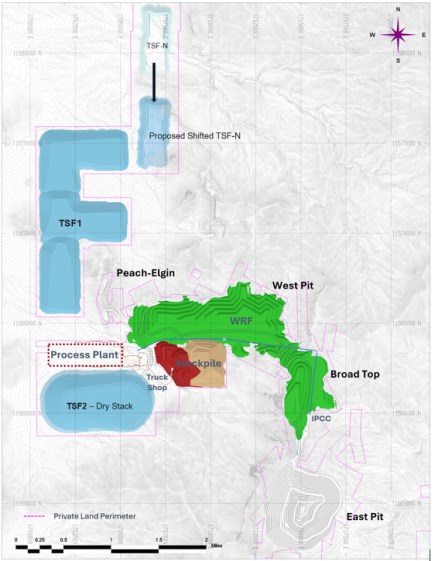
|
Economic material will be delivered to a processing flotation facility that has been optimized to treat both copper sulfides and copper-oxide mineralization to produce commercial-grade metal concentrates.
The main operational components of the project include the process plant, IPCC, waste rock facility (WRF), ore stockpiles, and the tailings storage facility (TSF).
In the Base Case, the mine operation has a 15-year life plus two years of pre-stripping. This life-of-mine (LOM) production plan accounts for 390 million tonnes of ore delivered to the mill and approximately 589 million tonnes of waste, resulting in an overall LOM stripping ratio of 1.5.
The production sequence prioritizes higher-grade ore and lower strip ratios in the early years, strengthening near-term economics and accelerating capital payback. This phased development strategy minimizes waste movement during initial production. As the mine matures, waste stripping transitions are managed smoothly to maintain adequate ore exposure, ensuring a consistent and reliable mill feed throughout the operation's life.
16.1 Mine Design
16.1.1 Mine Design Criteria
Pit designs and intermediate mining phases are developed from optimized pit limits and configured to support the deployment of large-scale equipment, ensuring efficient material movement and operational scalability. The primary equipment fleet includes:
• 10-5/8-inch diameter rotary blast hole drills
• 44-yd³ class hydraulic shovels
• 36-yd³ front-end loaders
• 320-ton capacity autonomous off-highway haul trucks.
Table 16-1: Base Pit Design Components
| Unit (ft) | ||
| Haul Road Width | ||
| Single Lane Road With | Ft | 81 |
| Base for Autonomous Double Lane Road Width | ft | 116 |
| Mining Constraints | ||
| Buffer to Property Limits - Competent/Rock | ft | 25.0 |
| Minimum Pit to Infrastructure Offset (minimum distance) | ft | 300.0 |
16.1.2 Mining Boundaries
The Base Case mine plan assumes that, during operations, the mine site will require only state and local permits, and that all mine facilities will be contained within the perimeter of Hudbay's private land holdings.
|
16.1.3 Minimum Mining Width
Minimum operating widths were established to guide pushback design, ensuring that engineered pits can be mined safely and efficiently with the selected mining fleet at the pit bottom. Table 16-2 summarizes these requirements: a minimum mining width of 120 ft at the ultimate pit bottom and a minimum operating width of 232 ft for internal mining phases (equivalent to two full double-lane road widths for 794AC trucks) to ensure optimum productivity.
Table 16-2: Minimum Mining Width
| Minimum Mining Width Parameter | Measurement (ft) |
| Target minimum mining width | 460 |
| Minimum mining width between pushbacks | 190 |
| Minimum mining width at pit bottom | 120 |
Based on the technical specifications for the primary loading unit and hauling equipment, Figure 16 2 illustrates the baseline for pit designs. Utilizing a CAT 6060 shovel paired with CAT 794 (320-ton class) haul trucks, an estimated minimum mining width of 57.6 meters (189 ft) represents a robust and well-proportioned baseline for design, serving as the reference standard for determining target distances between pushbacks.
Figure 16-2: Baseline for a pit pushbacks design utilizing a CAT 6060 shovel and CAT 794 or 795 trucks
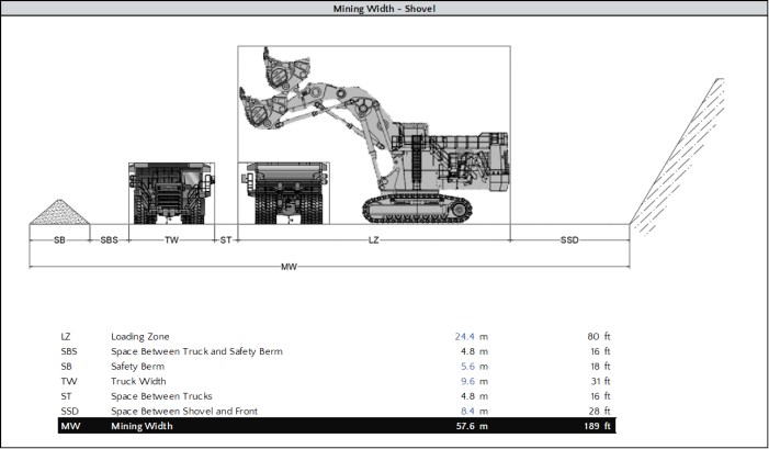
|
16.1.4 Haul Road Parameters
The mine design accommodates both staffed and autonomous haulage systems (AHS). All pit roads were designed to support either single- or dual-lane traffic for 320-ton haul trucks. Road specifications were established assuming a 320-ton haul truck equipped with a 6.1 ft tire radius.
Due to externally mounted sensor systems, AHS-equipped trucks are slightly wider (32 ft) than standard non-autonomous trucks (31 ft). Despite this wider physical profile, AHS trucks require a slightly narrower active running width for safe operation. Detailed road width specifications are presented in Table 16-3.
To maximize mineral resource recovery, particularly at the bottom of the economic pit limits, a running surface width multiplier of 2.85 times the truck width was assumed for determining the ultimate mining limits in the East Pit design. This assumption aligns directly with guidance from the manufacturer of the selected AHS equipment. For all other pit phases, a more conservative design approach was adopted, calculating dual-lane running widths at 3.0 times the truck width, and single-lane ramps at 2.0 times the truck width. Both multipliers are standard practice for North American mining operations utilizing manually operated trucks.
Typical road layouts are illustrated in Figure 16-3 for single-lane roads and Figure 16-4 for dual-lane roads. The haul roads were generally designed with a maximum gradient of 10%, which increases up to 12% at the pit bottom of the East Pit. All other pits maintain a maximum 10% gradient throughout. To further maximize ore extraction, single-lane ramps were typically utilized for the bottom three to four benches of the final pit phase.
Table 16-3: Haul Road Specifications
| Dimension | Measurements (ft) | |
| Single lane | Dual lane | |
| Safety Berm (SB) | 17 | 17 |
| Space Between Truck and Safety Berm (STB) | 8 | 8 |
| Truck Width (TW) | 31 | 31 |
| Space Between Trucks (ST) | NA | 16 |
| Space Between Truck and Ditch (STD) | 16 | 8 |
| Ditch Width (DW) | 8 | 8 |
| Ramp Width (RW) | 81 | 120 |
|
Figure 16-3: Single-Lane Road Layout
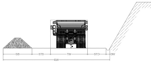
Figure 16-4: Dual-Lane Road Layout
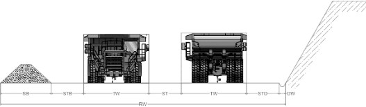
16.1.5 Pit Slope Guidance
The geotechnical firm Knight Piésold's (KP) recommended inter-ramp angles (IRA) for the East Pit are presented in Table 16-4, while the corresponding recommendations Peach-Elgin (PE), West (WP) and Broadtop Butte (BT) pits are provided in Table 16-5. The slope sector delineations for East Pit are illustrated in Figure 16-5, and the corresponding adjusted overall slope angles (OSA) are shown in Figure 16-6.
Table 16-4: East Pit IRA Recommendations with Ramp Adjustments
| Design | Rock Type | Upper- lower Boundary elevation |
Bench | Bench Height | BFA | IRA | Catch Bench | No. of | No. of | Total | Total | |
| Sector | Config | (feet) | (degrees) | (degrees) | (feet) | Ramps | Benches | Height | Width | OSA | ||
| EP_A | Upper | 4566 | Double | 100 | 75 | 53 | 49 | 0 | 10 | 975 | 686 | 54.9 |
| Lower | Double | 100 | 60 | 47 | 36 | 2 | 6 | 585 | 786 | 36.7 | ||
| EP_B | Upper | 4600 | Double | 100 | 75 | 47 | 66 | 0 | 13 | 1,280 | 1,194 | 47.0 |
| Lower | - | - | - | - | ||||||||
| EP_C | Upper | 4395 | Single | 50 | 70 | 46 | 30 | 1 | 22 | 1,090 | 1,173 | 42.9 |
| Lower | Double | 100 | 59 | 46 | 36 | 1 | 6 | 645 | 743 | 41.0 |
|
| Design | Rock Type | Upper- lower Boundary elevation |
Bench | Bench Height | BFA | IRA | Catch Bench | No. of | No. of | Total | Total | |
| Sector | Config | (feet) | (degrees) | (degrees) | (feet) | Ramps | Benches | Height | Width | OSA | ||
| EP_D | Upper | 4252 | Single | 50 | 72 | 51 | 24 | 1 | 17 | 856 | 813 | 46.5 |
| Lower | - | - | - | - | ||||||||
| EP_E | Upper | 4433 | Single | 50 | 52 | 38 | 25 | 1 | 14 | 685 | 997 | 34.5 |
| Lower | Double | 100 | 59 | 46 | 36 | 2 | 5 | 455 | 679 | 33.8 | ||
| EP_F | Upper | 4735 | Double | 100 | 63 | 49 | 36 | 1 | 9 | 880 | 885 | 44.8 |
| Lower | Double | 100 | 63 | 49 | 36 | 1 | 7 | 670 | 702 | 43.6 | ||
| EP_G | Upper | 4700 | Double | 100 | 60 | 47 | 36 | 1 | 6 | 620 | 698 | 41.6 |
| Lower | Double | 100 | 57 | 45 | 35 | 2 | 6 | 600 | 840 | 35.5 |
Table 16-5: Other Pits IRA Recommendations with Ramp Adjustments
| Design | Rock Type | Bench | Bench Height | BFA | IRA | Catch Bench | No. of | No. of | Total | Total | |
| Sector | Config | (feet) | (degrees) | (degrees) | (feet) | Ramps | Benches | Height | Width | OSA | |
| PE-A | All | Double | 100 | 75 | 58 | 36 | 1 | 3 | 300 | 156 | 51.8 |
| PE-B | All | Double | 100 | 73 | 57 | 34 | 1 | 3 | 300 | 154 | 50.6 |
| PE-C | All | Double | 100 | 74 | 58 | 34 | 1 | 4 | 400 | 188 | 52.9 |
| PE-D | All | Double | 100 | 70 | 55 | 34 | 2 | 5 | 500 | 307 | 45.6 |
| PE-E | All | Double | 100 | 66 | 52 | 34 | 2 | 2 | 200 | 240 | 31.3 |
| PE-F | All | Double | 100 | 74 | 58 | 34 | 1 | 3 | 300 | 154 | 51.4 |
| BT-A | All | Double | 100 | 50 | 40 | 35 | 1 | 5 | 500 | 226 | 37.8 |
| BT-B | All | Double | 100 | 73 | 57 | 34 | 1 | 5 | 500 | 223 | 53.1 |
| BT-C | All | Double | 100 | 70 | 55 | 34 | 1 | 5 | 500 | 221 | 51.1 |
| BT-D | All | Double | 100 | 50 | 40 | 35 | 2 | 4 | 400 | 275 | 33.2 |
| BT-E | All | Double | 100 | 56 | 44 | 36 | 1 | 6 | 600 | 264 | 41.9 |
| BT-F | All | Double | 100 | 71 | 55 | 36 | 1 | 6 | 600 | 262 | 52.0 |
| BT-G | All | Double | 100 | 50 | 40 | 35 | 1 | 3 | 300 | 155 | 36.4 |
| BT-H | All | Double | 100 | 71 | 55 | 36 | 0 | 3 | 300 | 71 | 59.8 |
| BT-J | All | Double | 100 | 70 | 55 | 34 | 1 | 5 | 500 | 221 | 51.1 |
| BT-K | All | Double | 100 | 71 | 55 | 36 | 1 | 7 | 700 | 298 | 52.4 |
| WP-A | All | Double | 100 | 75 | 58 | 36 | 1 | 3 | 300 | 156 | 51.8 |
| WP-B | All | Double | 100 | 73 | 57 | 34 | 1 | 3 | 300 | 154 | 50.6 |
| WP-C | All | Double | 100 | 74 | 58 | 34 | 1 | 4 | 400 | 188 | 52.9 |
| WP-D | All | Double | 100 | 70 | 55 | 34 | 2 | 5 | 500 | 307 | 45.6 |
| WP-E | All | Double | 100 | 66 | 52 | 34 | 2 | 2 | 200 | 240 | 31.3 |
| WP-F | All | Double | 100 | 74 | 58 | 34 | 1 | 3 | 300 | 154 | 51.4 |
|
Figure 16-5: East Pit Slope Sectors for Base Case
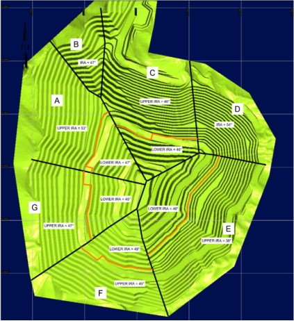
|
Figure 16-6: Overall Slope Angles by Sectors for All Pits
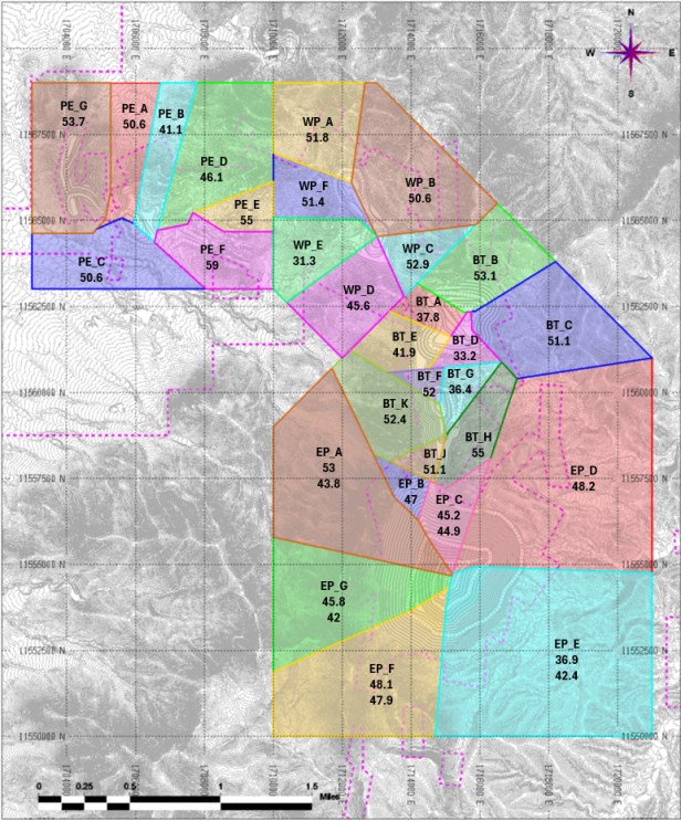
|
16.1.6 In-Pit Crushing & Conveying (IPCC)
The East Pit design incorporates an IPCC system for ore transport. As a critical component of the mine development, the IPCC system is projected to significantly reduce haul truck fleet requirements and the associated costs of transporting ore to the processing plant, and haulage emissions.
Run-of-mine (ROM) ore will be delivered by haul trucks discharging directly into the crusher dump pocket, while rehandled material from the stockpiles will be trammed to the feeder using a front-end loader. The system will utilize a 100,000 stpd (100 kstpd) gyratory crusher. Further details about the IPCC system are available in Section 18.
Once established, the system will transport ore using a combination of overland and suspended conveyors. The conveyor routing was optimized for efficiency and to minimize the impact in the capacity of the waste rock storage facilities (WRFs). As detailed in the subsequent sections, the pit mining and WRF deposition sequences were strategically developed to facilitate the construction of the IPCC system, which is scheduled for commissioning and operational readiness by Year 5 of production.
16.1.7 Ultimate Pit & Phases
Ore for the Project is sourced from four open pits: East, Broadtop Butte, West, and Peach-Elgin. The mining sequence strategy prioritizes the early extraction of higher-grade mineralization at lower strip ratios while maintaining balanced waste stripping throughout the mine life to ensure adequate ore exposure and a continuous supply of mill feed. Additionally, the strategy incorporates sequential pit backfilling to support the construction of the IPCC system.
Pit operations will be conducted on 50- and 100-foot-high benches.
In the Base Case, the extraction sequence across the four planned open pits is defined by 13 mining phases:
• The East Pit (4 Phases): This pit contains approximately 70% of the Project's mineral reserves. It is designed with an approximate diameter of 5,200 ft and a maximum depth of 1,600 ft. The East Pit is expected to expose an estimated 300 million tons of ore at an average grade of 0.49% Cu, with a corresponding strip ratio of 1.6.
• The Other Pits (9 Phases): The Peach-Elgin deposit comprises three mining phases, the Broadtop Butte consists of four, and the West Pit includes two. Reaching an average depth of 500 ft, these other deposits collectively expose approximately 150 million tons of ore, grading an average of 0.41% Cu with a highly favorable life-of-mine (LOM) strip ratio of 0.80.
|
Figure 16-7: Base Case: Plan view of the Project with Mine Phases
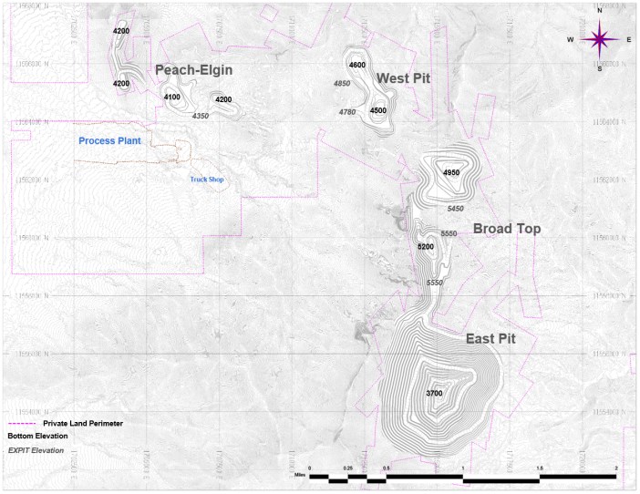
The internal mining phases were designed based on Lerchs-Grossmann (LG) analysis evaluated at various revenue factors, which generated a series of nested pit shells.
To establish the optimal mining sequence, the design prioritized rapid access to high-value ore as well as areas required for major infrastructure, such as the IPCC corridor. Furthermore, direct block scheduling outcomes generated via Deswik.GO were utilized as reference inputs to optimize the nested pit phases within the East Pit. This approach ensures expedited access to high-value ore sectors while minimizing early waste stripping requirements. The mineral grades of the final pit design, broken down by reserve category, are presented in Table 16-6.
|
Table 16-6: Base Case Mine Plan: Quantities by Mining Phases
| Phase | Ore ST (000's) | Cu (%) | CuSS(%) | Mo (ppm) | Ag (ppm) | Au (ppm) | Waste ST (000's) | SR | |
| Peach | PE-PH01 | 10,304 | 0.49 | 0.14 | 130.54 | 150.94 | 0.80 | 5,597 | 0.5 |
| PE-PH02 | 4,264 | 0.31 | 0.06 | 87.11 | 87.83 | 0.67 | 4,109 | 1.0 | |
| PE-PH03 | 2,265 | 0.52 | 0.27 | 59.78 | 138.07 | 0.62 | 6,784 | 3.0 | |
| Total | 16,833 | 0.45 | 0.14 | 110.02 | 133.22 | 0.74 | 16,490 | 1.0 | |
| West Pit | WP-PH01 | 27,276 | 0.47 | 0.16 | 147.05 | 104.10 | 0.41 | 16,200 | 0.6 |
| WP-PH02 | 11,072 | 0.34 | 0.06 | 84.46 | 71.00 | 0.34 | 6,189 | 0.6 | |
| Total | 38,349 | 0.43 | 0.13 | 128.98 | 94.54 | 0.39 | 22,389 | 0.6 | |
| Broadtop | BT-PH00 | 3,895 | 0.65 | 0.41 | 163.94 | 81.15 | 0.52 | 13,976 | 3.6 |
| BT-PH01 | 16,629 | 0.51 | 0.13 | 118.88 | 119.60 | 0.65 | 26,258 | 1.6 | |
| BT-PH02 | 46,840 | 0.28 | 0.03 | 128.45 | 89.16 | 0.33 | 29,375 | 0.6 | |
| BT-PH03 | 11,504 | 0.50 | 0.27 | 70.63 | 107.50 | 0.32 | 53,669 | 4.7 | |
| Total | 78,869 | 0.38 | 0.11 | 119.75 | 97.86 | 0.41 | 123,279 | 1.6 | |
| East Pit | EP-PH01 | 75,875 | 0.59 | 0.09 | 106.13 | 240.16 | 0.94 | 151,653 | 2.0 |
| EP-PH02 | 62,224 | 0.40 | 0.08 | 90.15 | 214.40 | 0.89 | 75,482 | 1.2 | |
| EP-PH03 | 46,125 | 0.42 | 0.07 | 77.04 | 190.68 | 0.86 | 74,198 | 1.6 | |
| EP-PH04 | 123,423 | 0.47 | 0.10 | 94.44 | 176.70 | 0.92 | 185,294 | 1.5 | |
| Total | 307,647 | 0.48 | 0.09 | 93.85 | 202.07 | 0.91 | 486,627 | 1.6 | |
| Grand Total | 441,698 | 0.46 | 0.10 | 102.14 | 171.50 | 0.77 | 648,784 | 1.5 | |
Note: CuSS refers to the sulfide-soluble copper.
16.1.7.1 East Pit Phases
In the Base Case, the East pit has been sub-divided into four internal phases, as illustrated in Figure 16-8. A representative cross-section through the phases with the Cu grade is presented in Figure 16-9. The East Pit phases are the main source of ore for the LOM plan at a strip ratio of approximately 1.6:1.
|
Figure 16-8: Overall Pits Extents - Base Case
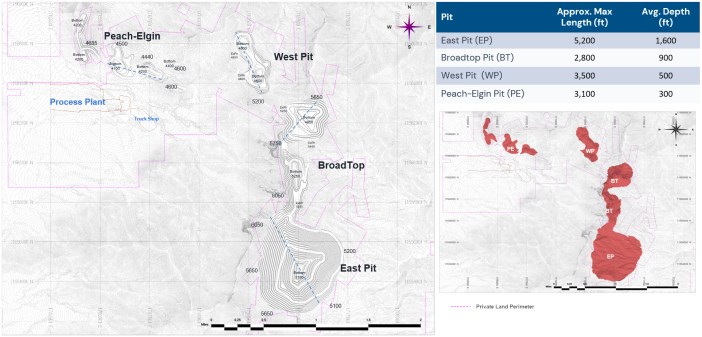
|
Figure 16-9: East Pit Section View - Mining Phases
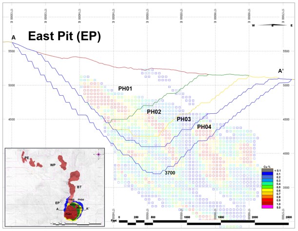
Phase 01
Representing the first major production stage, Phase 01 targets the higher-value portion of the East Pit deposit. Mining progression during this phase allows for the development of primary haul roads and establishes vital connections to the processing and waste management facilities. Phase 01 will extract approximately 75.9 million tons of ore at an average grade of 0.59% Cu, with a strip ratio of 2:1.
Phases 02 and 03
These phases expand the pit toward the southeast portion of the deposit. Phase 02 will mine approximately 62.2 million tons of ore at an average grade of 0.40% Cu, with a strip ratio of 1.2:1. Phase 03 will extract an additional 46.1 million tons of ore grading 0.42% Cu, with a strip ratio of 1.6:1. Although both phases share the same nested pit shell from the optimization stage, they were sequenced progressively, guided by outcomes from an early direct block schedule, to improve the direct mill feed profile and optimize waste stripping.
|
Phase 04
As the final stage of pit expansion, Phase 04 extends mining toward the eastern limits of the deposit. This phase will mine approximately 123.4 million tons of ore at an average grade of 0.47% Cu, with a strip ratio of 1.5:1, ultimately completing the final pit limits.
East Pit Summary
In the Base Case, the mining phases within the East Pit will extract approximately 307 million tons of ore at an average grade of 0.48% Cu, achieving an overall strip ratio of 1.6:1.
In addition to the East pit, the Base Case incorporates the Peach-Elgin, Broadtop, and West open pits as additional sources of mineral reserves (Figure 16-8).
16.1.7.2 Peach-Elgin Pit Phases
Peach-Elgin has three phases - Ph01, Ph02 and Ph03 as shown in Figure 16-10. Peach-Elgin will expose 16.9 million tons of Ore with an average grade of 0.45% Cu and a strip ratio of 1:1.
Figure 16-10: Section View - Peach-Elgin Pit Mine Phases
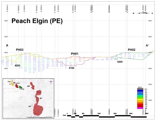
|
16.1.7.3 West Pit Phases
West Pit has two phases and is shown in Figure 16-11. West pit will expose 38.3 million tons of Ore with an average grade of 0.43% Cu and a strip ratio of 0.6:1.
Figure 16-11: Section View - West Pit Mine Phases
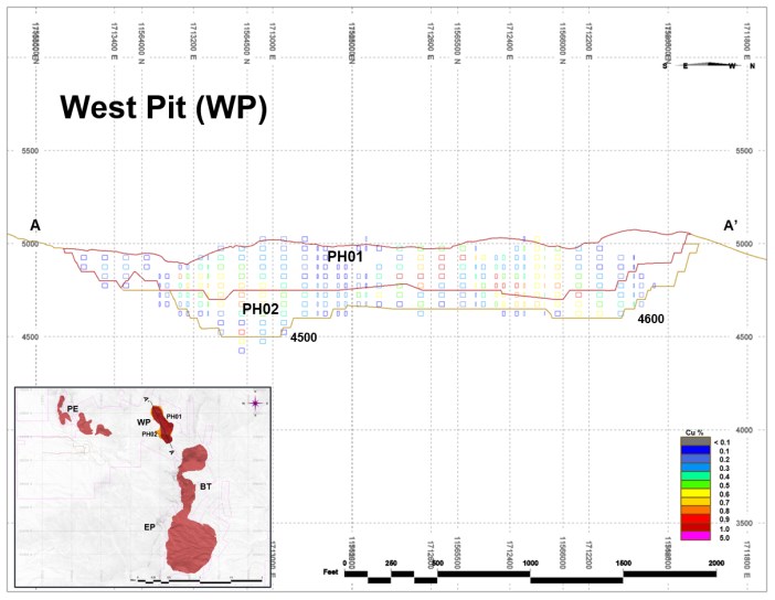
16.1.7.4 Broadtop Butte Pit Phases
The Broadtop Butte Pit is designed with four distinct mining phases, as illustrated in the figure below. In total, the pit is expected to expose 78.9 million tons of ore at an average grade of 0.38% Cu, with a strip ratio of 1.6:1.
|
Mining operations in the south pit area will commence with Phase 00. This initial, smaller phase is specifically designed to establish a primary access connection to the East Pit deposit and to support the early development of mine infrastructure. Phase 00 is projected to extract approximately 3.9 million tons of ore at an average grade of 0.65% Cu, with a corresponding strip ratio of 3.6:1.
Figure 16-12: Section View - Broadtop Butte Pit Mine Phases
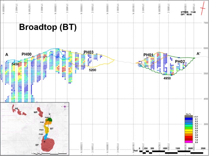
16.2 Mine Schedule & Production Plan
16.2.1 LOM Production Schedule - Base Case
The Life of Mine (LOM) production schedule was developed in detail using Hexagon's MinePlan Strategic Optimizer™ (MPSO). This detailed plan was based on an initial mining strategy established using Minemax software. Minemax was utilized to evaluate multiple scenarios and balance various operational constraints - including mine sequencing, processing, blending, waste dump scheduling, and trucking - to ultimately maximize the schedule's Net Present Value (NPV).
|
The open pit schedule consists of the following primary stages:
• Pre-Production Period (Years -2 and -1): A two-year pre-production phase is planned. During this time, the owner-operated mining fleet will execute all large fleet pre-stripping activities, supplemented by a mining contractor executing specialized pioneering pit access development.
• Steady-State Production & Expansion: Production will be sustained at 60 kstpd until Year 5, at which point the mill will be expanded to a capacity of 90 kstpd (Table 16-7).
• Stockpile Reclaiming Period (Years 13 and 15): During the final years of the LOM, operations will transition to stockpile reclaim. It is estimated that approximately 74 million tons of low-grade ore will be reclaimed and processed during this period.
Production Totals and Material Movement
The Base Case mine plan results in a total of 1,090.5 million tons of material mined from the open pit over the active mining life. This total comprises about 441.7 million tons of ore potentially economic to mine and process and 648.8 million tons of waste, resulting in an overall LOM average strip ratio of 1.47:1.
Active mining capacity ramps up over several years and is sustained at approximately 110 million tons of total material moved per year from Year 3 through Year 8. When accounting for both active pit mining and the rehandling of stockpiled material, the total material moved over the entire LOM reaches 1,236.6 million tons.
Table 16-7: Mine Schedule LOM
| Period | PP-02 | PP-01 | Y01 | Y02 | Y03 | Y04 | Y05 | Y06 | Y07 | Y08 | Y09 | Y10 | Y11 | Y12 | Y13 | Y14 | Y15 | Grand Total |
| Ore Tons ('000s) | 1,020 | 6,797 | 26,277 | 32,546 | 39,371 | 40,266 | 43,401 | 42,366 | 45,227 | 34,159 | 32,293 | 37,841 | 46,432 | 13,733 | 0 | 0 | 0 | 441,698 |
| PE | 690 | 1,116 | 13,641 | 1,386 | - | - | - | - | - | - | - | - | - | - | - | - | - | 16,833 |
| WP | 293 | 5,087 | 10,977 | 12,956 | 9,035 | - | - | - | - | - | - | - | - | - | - | - | - | 38,349 |
| BT | 37 | 563 | 1,659 | 18,204 | 29,277 | 29,129 | - | - | - | - | - | - | - | - | - | - | - | 78,869 |
| EP | - | - | - | - | 1,058 | 11,137 | 43,401 | 42,366 | 45,277 | 34,159 | 32,293 | 37,841 | 46,432 | 13,733 | - | - | - | 307,647 |
| Direct To Mill Tons ('000s) | - | - | 12,540 | 17,258 | 14,724 | 16,869 | 26,501 | 31,511 | 32,850 | 26,538 | 27,130 | 31,782 | 32,850 | 13,697 | 0 | 0 | 0 | 284,250 |
| To StockPilesTons ('000s) | 1,020 | 6,797 | 13,737 | 15,288 | 24,647 | 23,396 | 16,900 | 10,855 | 12,377 | 7,620 | 5,163 | 6,059 | 13,582 | 36 | 0 | 0 | 0 | 157,447 |
| Waste Tons ('000s) | 3,880 | 24,941 | 31,085 | 60,137 | 70,629 | 69,734 | 66,599 | 67,434 | 64,773 | 75,523 | 67,365 | 41,834 | 4,716 | 135 | 0 | 0 | 0 | 648,784 |
| PE | 1,810 | 2,749 | 11,480 | 451 | - | - | - | - | - | - | - | - | - | - | - | - | - | 16,490 |
| WP | 672 | 5,632 | 6,366 | 5,742 | 3,977 | - | - | - | - | - | - | - | - | - | - | - | - | 22,389 |
| BT | 1,398 | 16,560 | 13,239 | 53,944 | 31,772 | 6,366 | - | - | - | - | - | - | - | - | - | - | - | 123,279 |
| EP | - | - | - | - | 34,881 | 63,369 | 66,599 | 67,434 | 64,773 | 75,523 | 67,365 | 41,834 | 4,716 | 135 | - | - | - | 486,627 |
| Mined Tons ('000s) | 4,900 | 31,708 | 57,362 | 92,683 | 110,000 | 110,000 | 110,000 | 109,800 | 110,000 | 109,681 | 99,658 | 79,675 | 51,148 | 13,868 | 0 | 0 | 0 | 1,090,482 |
| PE | 2,500 | 3,865 | 25,121 | 1,837 | - | - | - | - | - | - | - | - | - | - | - | - | - | 33,323 |
| WP | 965 | 10,719 | 17,343 | 18,698 | 13,012 | - | - | - | - | - | - | - | - | - | - | - | - | 60,738 |
| BT | 1,435 | 17,124 | 14,898 | 72,148 | 61,049 | 35,494 | - | - | - | - | - | - | - | - | - | - | - | 202,148 |
| EP | - | - | - | - | 35,939 | 74,506 | 110,00 | 109,800 | 110,000 | 109,681 | 99,658 | 79,675 | 51,148 | 13,868 | - | - | - | 794,274 |
| SR (W:O) | 3.80 | 3.69 | 1.18 | 1.85 | 1.79 | 1.73 | 1.53 | 1.59 | 1.43 | 2.21 | 2.09 | 1.11 | 0.10 | 0.01 | - | - | - | 1.47 |
| Rehandle Ore Tons ('000s) | 0 | 0 | 3,948 | 4,642 | 7,176 | 5,091 | 6,349 | 1,339 | 0 | 6,402 | 5,720 | 1,068 | 0 | 19,243 | 32,850 | 32,850 | 19,401 | 146,079 |
| Material Moved Tons ('000s) | 4,900 | 31,708 | 61,310 | 97,326 | 117,176 | 115,091 | 116,349 | 111,139 | 110,000 | 116,083 | 105,378 | 80,743 | 51,148 | 33,111 | 32,850 | 32,850 | 19,401 | 1,236,561 |
| Ore Stock Tons ('000s) | 1,020 | 7,787 | 17,576 | 28,299 | 45,770 | 64,075 | 74,626 | 84,309 | 96,687 | 97,905 | 97,348 | 102,339 | 115,921 | 97,216 | 64,718 | 32,008 | 12,607 | 12,607 |
|
Figure 16-13: Mine Material Movement
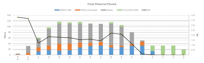
Mill Feed Strategy and Processing Deliverables
Over the 15-year operational life, the process plant will mill a total of 430.3 million tons of ore. The mill feed is sourced from 284.3 million tons of direct Run-of-Mine (ROM) ore and 146.1 million tons of reclaimed stockpile material.
The overall LOM average total copper grade (TCu) is 0.47%, with an average projected metallurgical copper recovery of 72.7%. The ore processed is predominantly copper sulfides; over the LOM, the proportion of Primary Sulfides (PSulph) and Secondary Sulfides (SSulph) averages approximately 81% of the total processed ore. Minor mineralogical contributions from geothite, carbonate, wads, and silicates are primarily encountered in the earlier years of the mine life (Pre-Production through Year 3) before the sulfide zones become heavily dominant.
Table 16-8: Mine Production Schedule Criteria
| Parameter | Year 01 | Year 02 to Year 04 | Year 05 to Year 15 |
| Annual Ore Milled Base Rate (Tons) | 16,488,000 | 21,900,000 | 32,850,000 |
| Daily Ore Milled Base Rate (Tons) | 45,000 | 60,000 | 90,000 |
| Operating Hours per Shift | 12 | 12 | 12 |
| Operating Shift per Day | 2 | 2 | 2 |
| Operating Days per Week | 7 | 7 | 7 |
| Scheduler Operating Days per Year | 365 | 365 | 365 |
| Number of Mine Crews | 4 | 4 | 4 |
Table 16-9: Mill Feed Production Schedule
| Period | YR01 | YR02 | YR03 | YR04 | YR05 | YR06 | YR07 | YR08 | YR09 | YR10 | YR11 | YR12 | YR13 | YR14 | YR15 | Grand Total |
| Mill Tons ('000s) | 16,488 | 21,900 | 21,900 | 21,960 | 32,850 | 32,850 | 32,850 | 32,940 | 32,850 | 32,850 | 32,850 | 32,940 | 32,850 | 32,850 | 19,401 | 430,329 |
| SCu (%) | 0.45% | 0.43% | 0.38% | 0.40% | 0.50% | 0.69% | 0.41% | 0.34% | 0.33% | 0.41% | 0.56% | 0.32% | 0.11% | 0.08% | 0.07% | 0.37% |
| CuSS (%) | 0.21% | 0.21% | 0.12% | 0.09% | 0.12% | 0.08% | 0.09% | 0.11% | 0.09% | 0.08% | 0.07% | 0.08% | 0.07% | 0.07% | 0.08% | 0.10% |
| Cu (%) | 0.66% | 0.64% | 0.49% | 0.49% | 0.62% | 0.78% | 0.50% | 0.45% | 0.42% | 0.49% | 0.63% | 0.40% | 0.17% | 0.15% | 0.14% | 0.47% |
| Au (Oz/Ton) | 0.0006 | 0.0005 | 0.0005 | 0.0004 | 0.0008 | 0.0011 | 0.0011 | 0.0007 | 0.007% | 0.0009 | 0.0013 | 0.0009 | 0.0004 | 0.0003 | 0.0003 | 0.0007 |
| Ag (Oz/Ton) | 0.1300 | 0.1142 | 0.1142 | 0.1566 | 0.2414 | 0.2898 | 0.1737 | 0.1391 | 0.1514 | 0.1736 | 0.2487 | 0.1634 | 0.0938 | 0.0915 | 0.0822 | 0.1632 |
| Mo (%) | 0.02% | 0.01% | 0.01% | 0.01% | 0.01% | 0.01% | 0.01% | 0.01% | 0.01% | 0.01% | 0.01% | 0.01% | 0.01% | 0.01% | 0.01% | 0.01% |
|
16.2.2 Detailed Stockpile Management and Segregation Strategy
Net Smelter Return (NSR) values are used to represent the economic value of each block in the block model and dictate the cut-off strategy used for mine planning. A marginal NSR cut-off value of US$5.80/ton was applied to cover processing costs (US$5.07/ton) and general and administrative (G&A) costs (US$0.73/ton). All blocks within the outlined pit designs that exceed this value are considered economically viable for processing. However, as noted in Section 15, an additional cut-off of 0.1% Cu and 48% flotation recovery were utilized for production scheduling due to the overall ore reserves being constrained by the available tailing's storage capacity.
To maximize near-term cash flow, a comprehensive stockpiling strategy prioritizes the processing of higher-grade material during the early years of operation. This approach guarantees a continuous, full-capacity mill feed during periods of high strip ratios while maintaining deleterious elements within acceptable plant thresholds.
Physical space restrictions imposed by the current property boundaries require the implementation of 3D block-modelled stockpiles to effectively manage the limited operational footprint. Ore is actively segregated into specific grade bins - High-Grade (HG), Medium Grade (MG), Low Grade (LG), and Very Low Grade (VLG). While the ultimate footprint can accommodate up to 130 million tons of storage, the optimized schedule dictates the following inventory dynamics:
• Total Inventory: The combined stockpile inventory reaches an absolute peak balance of 115.9 million tons in Year 11.
• HG Stockpile: Peaks early in the mine life, reaching a maximum required capacity of 9.2 million tons in Year 3 before being drawn down to feed the mill in Years 4 and 5.
• MG Stockpile: Peaks mid-mine life, reaching a maximum balance of 31.0 million tons in Year 7.
• LG Stockpile: Requires the largest containment footprint, accumulating steadily alongside waste stripping to reach a peak balance of 70.1 million tons in Year 11.
• Reclaim Only Phase: After active pit mining ceases at the end of Year 12, operations transition exclusively to reclaiming these lower-grade stockpiles. The mill reclaims over 22.0 million tons of LG material in Year 13 and 32.7 million tons in Year 14.
|
Figure 16-14: Base Case: Plant Feed Mill Tonnages by Year
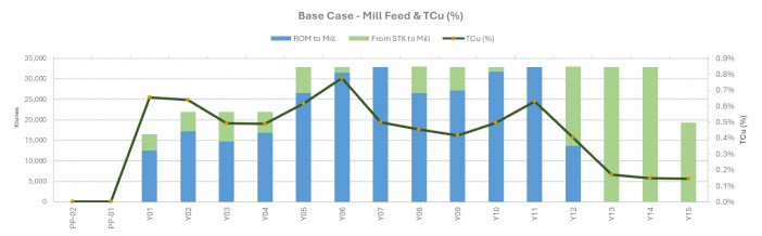
Figure 16-15: Mineral Resource Certainty by Year
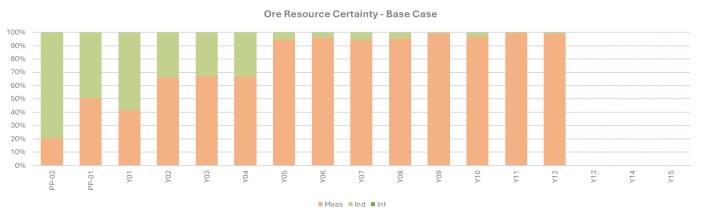
16.2.3 Waste Rock Facility Design
Overburden and other uneconomic rock exposed during ore extraction will be placed into the Waste Rock Facilities (WRFs). The design criteria for the WRFs and associated haul roads are summarized in Table 16-10.
Table 16-10: WRF Design Criteria
| Parameter | Values | Unit |
| Angle of Repose | 37 | Degrees |
| OSA | 24.4 | Degrees |
| Average Tonnage Factor with swell | 15.62 | ft3/ton |
| Lift height | 100 | ft |
| Haul Road | 120 | ft |
|
Waste will be end-dumped in 100 ft high lifts, maintaining dump faces at the natural angle of repose (37°). The WRF crests will be strategically set back to allow for simple dozing to achieve the target re-graded slope angles (24.4°), which will support reclamation efforts.
The current WRF design integrates the IPCC system into the construction sequence, providing a total nominal storage capacity of approximately 600 million tons (Mt) in the Base Case. This capacity is achieved through planned lift optimizations and careful footprint management. The mine plan also includes routing approximately 50 Mt of waste material to the secondary tailings storage facility (TSF2).
Furthermore, upon the completion of mining activities in the Peach-Elgin, Broadtop Butte, and West pits, these excavated areas will be backfilled and utilized to further expand the waste rock storage capacity.
Figure 16-16: WRF Plan View
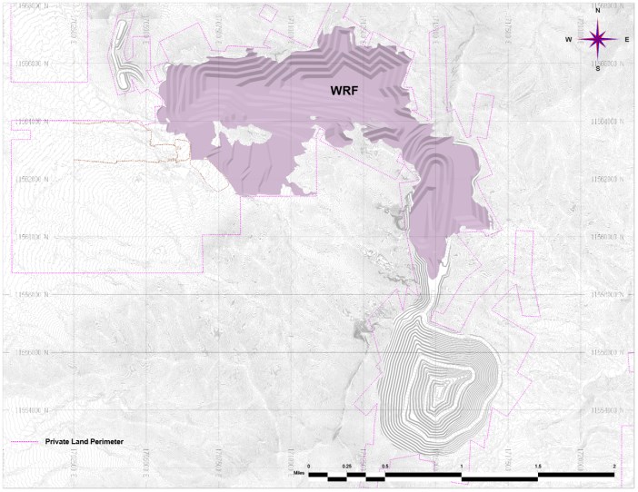
|
16.2.4 Base Case: Mining Sequence
The mine schedule was prepared using the Hexagon MinePlan Schedule Optimizer (MPSO, configured to optimize the extraction sequence for Net Present Value (NPV). Mine plan layouts, alongside detailed descriptions of the key mining activities, are presented in Figure 16-16 to Figure 16-21.
The production schedule is aligned directly with the process plant throughput profile. The initial processing rate during Year 1 to 4 is designed for an average throughput of 60 kstpd). A plant expansion will increase capacity to 90 kstpd at the beginning of Year 5, maintaining this rate for the remainder of active operations.
Throughout the life of mine (LOM), ore will be actively blended to deliver a consistent, mill feed profile that maximizes metallurgical recoveries in the concentrator. Ore is stockpiled according to NSR grade and metallurgical characteristics, then reclaimed as needed. The stockpile balance peaks at approximately 116 million short tons (Mst) at the end of Year 11.
Pre-Production: Year -2
The pre-production period begins in Year -2, targeting the extraction of 2.5 Mst from the Peach-Elgin pit, 1.4 Mst from the Broadtop Butte pit, and an initial 965 kst from the West Pit. Mining these other pits is prioritized to strip overlying waste and source the waste rock required to construct ore stockpile pads, road bases, and infrastructure, as well as to prepare the IPCC corridor for development.
Pre-Production: Year -1
Pre-production development continues throughout Year -1 (illustrated in Figure 16-16). Material extraction scales up to 3.9 Mst from Peach-Elgin, 10.7 Mst from West Pit Phase 1, and 17.1 Mst from Broadtop Butte Phases 0 and 3. Waste rock generated during this phase continues to support the construction of the IPCC corridor. As in Year -2, all ore mined during this period is stockpiled for future processing.
|
Figure 16-17: Mining and Dumping Areas - Pre-Production - YR - 1
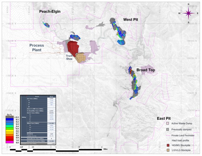
Production: Years 1 - 3
The mine officially enters the production phase in Year 1, with 16.5 Mst of ore scheduled for processing. Plant production ramps up according to the schedule outlined in Table 16-9. Most mill feed is sourced directly from run-of-mine (ROM) production, supplemented by 3.9 Mst reclaimed from pre-production stockpiles. In total, 57.4 Mst of material is scheduled to be mined in Year 1.
During the first three years, operations will expand from West Pit Phase 2, Peach-Elgin Phase 1, and Broadtop Butte Phase 0. This period marks the completion of mining in the other pits and the initiation of mining in the East Pit. Waste rock placement continues to prioritize the construction of the IPCC corridor wherever possible. Year 3 is illustrated in Figure 16-18.
|
Figure 16-18: Mining and Dumping Areas in YR - 03
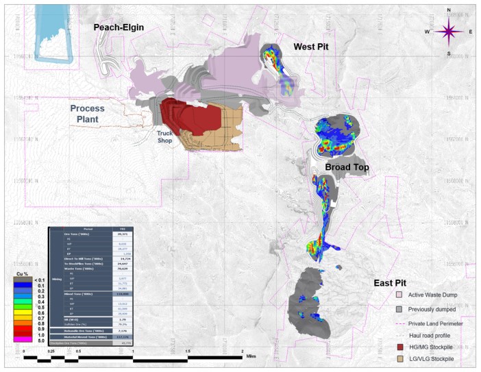
Production: Year 4 & IPCC Commissioning
Pit operations maintain a total production rate of 110 Mst in Year 4. Active pit production is primarily focused on Broadtop Butte Phase 2 and East Pit Phase 1, which collectively yield 40 Mst of ore. Mining within the IPCC corridor and the required waste rock backfilling of West Pit and Broadtop Butte Phase 3 are also completed during this year. These milestones finalize the IPCC system construction, positioning the system to begin conveying ore in Year 5.
Near the start of East Pit development, an In-Pit Crusher (IPC) will be commissioned to process East Pit ore for conveyor delivery to the plant. To cross high-relief terrain, the initial two conveyor flights from the IPC will feature an aerial conveyor system, transferring material to a conventional overland conveyor for final transport. A portion of crushed ore from the IPC circuit will also be routed to crushed ore stockpiles near the plant to support downstream mill feed blending.
|
Production: Year 5
In Year 5, production within the East Pit continues across Phases 1 through 3. The processing plant expands its capacity to 90 kstpd, equating to approximately 32.85 million short tons per annum (Mstpa). All excavated waste rock is routed north and placed within the Waste Rock Facilities (WRFs), utilizing the depleted Broadtop Butte pit for backfilling. The mine plan for Year 5 is illustrated in Figure 16-19.
Figure 16-19: Mining and Dumping Areas - YR - 05
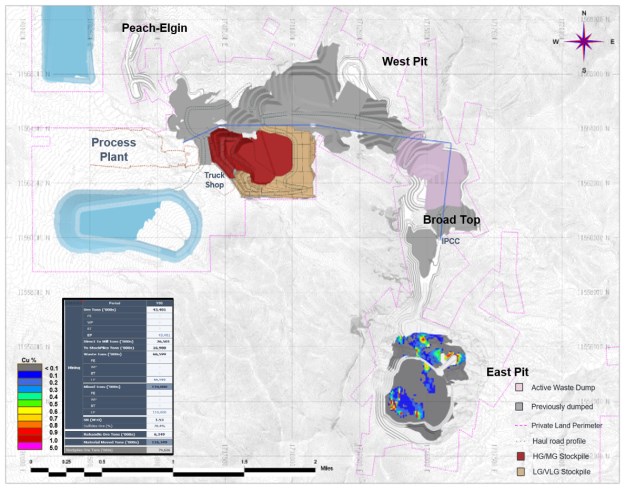
|
Production: Years 6-10
From Year 6 through Year 10, production within the East Pit continues across Phases 1 and 4. The operation maintains a steady ore processing rate of 90 kstpd, while total mining capacity begins to decrease from 110 Mstpa in Year 8 to 80 Mstpa in Year 10.
Mining operations in East Pit Phase 1 are completed in Year 7, followed by the depletion of Phase 2 in Year 8. All excavated waste rock is hauled north to the WRFs, utilizing the depleted West and Peach-Elgin pit areas for backfill. The mine plan at the end of Year 10 is illustrated in Figure 16-20.
Figure 16-20: Mining and Dumping Areas in YR - 10
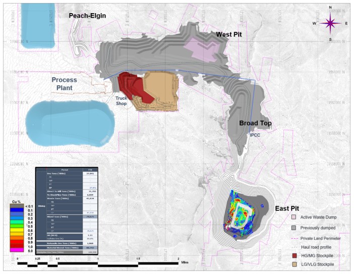
|
Years 12 - 15: Stockpile Reclaim & End of Mine Life
All active pit mining operations conclude in Year 12 following the final depletion of East Pit Phase 4 (Figure 16-21). From Year 13 through Year 15, the mill feed is sustained entirely by reclaiming 85 Mst of ore from long-term stockpiles.
At the end of the processing schedule, approximately 12 Mst of otherwise economically viable material remains in the low-grade stockpiles. This material is left unprocessed because there is insufficient capacity remaining in the Tailings Storage Facility to store the generated tailings. The ultimate mine configuration and final site layout at the end of Year 15 are illustrated in Figure 16-22.
Figure 16-21: Mining and Dumping Areas - YR - 12 (Mining Completed)
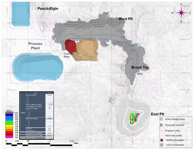
|
Figure 16-22: Pits and Rock Storage Facilities at the End of YR - 15 (End of Life of Mine)
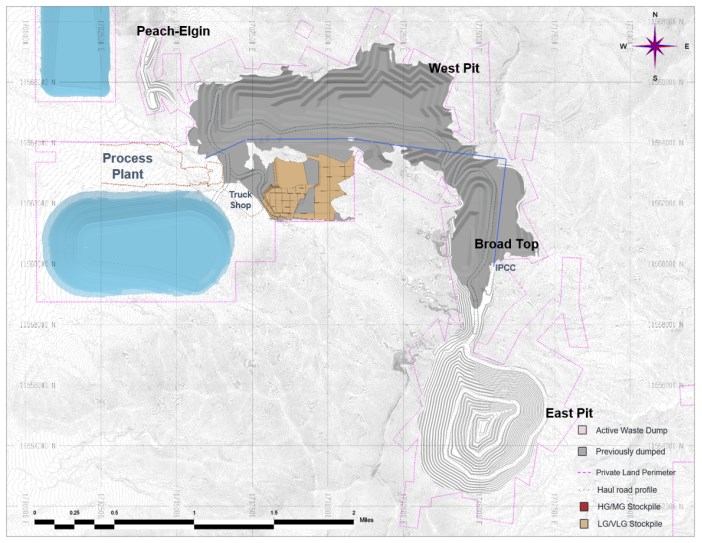
16.3 Mine Fleet
The mining fleet was selected based on annual production requirements, according to the mining schedule shown in , as well as ongoing stockpile rehandling needs.
Primary mining equipment (Shovels, Loaders, Trucks and Drills) operating hours were estimated by applying calculated expected productivities to the scheduled material movements. Ancillary mining equipment (dozers, graders, water trucks, support excavators, and service trucks) operating hours were estimated using specific support ratios relative to the primary mining fleet. Further details are discussed in Section 16.3.3.
|
The expected equipment fleet numbers were estimated by dividing the total estimated operating hours by the annual average operating hours, determined using site-specific availability and utilization assumptions. A summary of the average operating hours and expected equipment is shown in Table 16-11.
Table 16-11: Mine Equipment Operating Assumptions
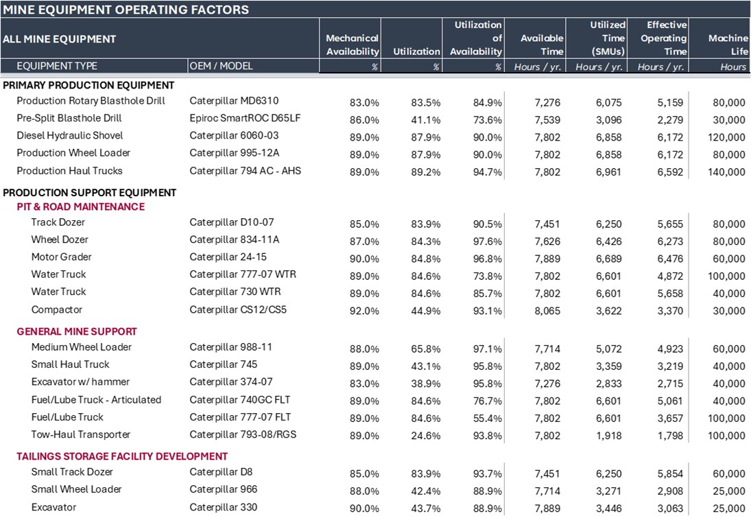
16.3.1 Loading and Hauling Fleet
The operation will utilize conventional open-pit mining methods utilizing a primary production fleet of large-diameter single-pass blasthole drills, 44 yd³ hydraulic shovels, 36 yd³ wheel loaders, and 320-ton payload haul trucks. A complete auxiliary fleet, including track and wheel dozers, motor graders, and water trucks, will support primary production. The owner's haul truck fleet will be fully integrated with an Autonomous Haulage System (AHS) from initial commissioning.
Once contractor-led pioneering work establishes initial working benches suitable for ultra-class production equipment, full-scale owner's mining will commence. The sequence prioritizes extraction from the smaller other pits during early production before transitioning primary operations to the main East Pit for the remainder of the active mining phase.
|
Mining will take place on 50-foot-high benches to optimize the digging envelopes of the production of shovels and wheel loaders. Waste rock will be routed to designated waste rock storage facilities (WRFs). Run-of-mine (ROM) ore will be hauled directly to the primary crusher at the process plant or to dedicated stockpile locations for future reclaiming and blending.
Pass matching parameters for the load and haul fleet are presented in Table 16-12.
Table 16-12: Loader and Truck Pass-Match Parameters
| Item | Unit | Shovel | Loader |
| Material Type | Waste | Ore | |
| Dry Bank Density | yd3/st | 2.26 | 2.26 |
| Swell factor (SF) | % | 40 | 35 |
| Moisture | % | 3.5 | 3.5 |
| Rated bucket capacity (lcy) | yd3 | 44.5 | 36 |
| Rated bucket capacity | m3 | 34.0 | 29.1 |
| Bucket fill factor | % | 88 | 88 |
| Tons/pass | st (dry) | 63.1 | 53 |
| st (wet) | 65.3 | 54.8 | |
| Rated truck size (payload) | st (dry) | 327.0 | 327.0 |
| st (wet) | 328.0 | 328.0 | |
| Theoretical passes | # | 5.2 | 6.2 |
| Passes | # | 5.00 | 6.00 |
| Practical truck size | st (wet) | 327.0 | 327.0 |
| Time per pass | min | 0.63 | 0.75 |
| Truck spot time | min | 0.42 | 0.67 |
| Total loading time | min | 3.17 | 4.50 |
| Average Minutes per truck | min | 3.58 | 4.50 |
| Max Trucks Loaded per hours | unit | 16.7 | 11.6 |
| Max Production | st / hr | 5,475 | 3,797 |
| Availability | % | 89.0% | 89.0% |
| UoA | % | 90.0% | 90.0% |
| Operating Efficiency | % | 87.4% | 87.4% |
| Job Efficiency | % | 91.7% | 91.7% |
| Hourly Production | st/hr | 4,386 | 3,042 |
| Hourly Effective Production | st/hr | 3,513 | 2,437 |
| Operating Hours Shift | hr | 8 | 8 |
| Shifts per year | unit | 1,095 | 1,095 |
| Annual Production | TPY x 1000 | 30,777 | 21,345 |
|
The loading equipment has been selected to operate on 50ft bench heights and to load 320-Ton class haul trucks. The loading fleet requirements by period are presented in Figure 16-23, and the haulage fleet is presented in Figure 16-24.
Figure 16-23: Primary Loading Equipment Requirement
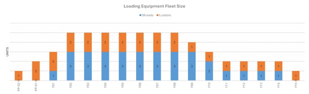
Figure 16-24: Primary Haulage Equipment Requirement
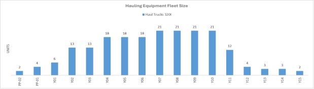
The total amount of Haul Trucks required reflects the planned integration of an IPCC system, which will transport the ore from the East Pit to the process plant starting in Year 5.
16.3.2 Drilling & Blasting
The drill and blast parameters used in the cost estimate and fleet sizing are summarized in Table 16-13. Primary drilling equipment requirements by period are presented in Figure 16-25.
Table 16-13: General Drill and Blast Design Parameters
| PARAMETERS | UNITS | PRODUCTION BLASTHOLES | PRE-SPLIT BLASTHOLES |
|||
| WASTE ROCK | ORE | |||||
| Dry | Wet | Dry | Wet | |||
| Drill | Caterpillar MD6310 | Epiroc D65LF | ||||
| Hole Diameter | inches | 10 5/8 | 10 5/8 | 10 5/8 | 10 5/8 | 6 1/2 |
|
| PARAMETERS | UNITS | PRODUCTION BLASTHOLES | PRE-SPLIT BLASTHOLES |
|||
| WASTE ROCK | ORE | |||||
| Dry | Wet | Dry | Wet | |||
| Bench | ft | 50 | 50 | 50 | 50 | 50 |
| Subdrill | ft | 7 | 7 | 5 | 5 | - |
| Wall / Hole Angle | degrees | 90 | 90 | 90 | 90 | 70 |
| Total Hole Depth | ft | 57 | 57 | 55 | 55 | 53.2 |
| Burden | ft | 29 | 29 | 25 | 25 | - |
| Spacing | ft | 33 | 33 | 29 | 29 | 7 |
| Stemming Height | ft/hole | 20 | 22 | 18 | 20 | - |
| Stemming Density (Loose) | lbs. / ft3 | 120 | 120 | 120 | 120 | - |
| Powder Factor | lbs Expl / st | 0.34 | 0.40 | 0.44 | 0.53 | - |
Figure 16-25: Primary Drilling Equipment Requirement
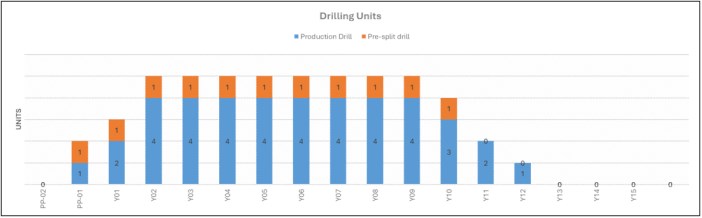
16.3.3 Support Equipment
Major support equipment consists of ancillary machines that facilitate safe and efficient primary mining operations. The equipment is scheduled to maintain in-pit and ex-pit haul roads, pit benches, waste storage facilities and tailings storage facilities.
The anticipated support equipment fleet models and categories are outlined in Table 16-14
Table 16-14: Ancillary Mining Fleet
| Operational Area | Equipment Type | Proposed Model |
| Pit & Road Maintenance | Track Dozer | Caterpillar D10-07 |
| Wheel Dozer | Caterpillar 834-11A | |
| Motor Grader | Caterpillar 24-15 | |
| Water Truck (Rigid) | Caterpillar 777-07 WTR | |
| Water Truck (Articulated) | Caterpillar 730 WTR | |
| Compactor | Caterpillar CS12 / CS5 |
|
| Operational Area | Equipment Type | Proposed Model |
| General Mine Support | Medium Wheel Loader | Caterpillar 988-11 |
| Small Haul Truck | Caterpillar 745 | |
| Excavator w/ Hammer | Caterpillar 374-07 | |
| Fuel/Lube Truck (Articulated) | Caterpillar 740GC FLT | |
| Fuel/Lube Truck (Rigid) | Caterpillar 777-07 FLT | |
| Tow-Haul Transporter | Caterpillar 793-08 / RGS | |
| Tailings Facility Dev. | Small Track Dozer | Caterpillar D8 |
| Small Wheel Loader | Caterpillar 966 | |
| Excavator | Caterpillar 330 |
Ancillary equipment hours and units were calculated using fixed ratios based on the active primary equipment:
• Track Dozers (Loading Support): 1 unit per 2 loaders/shovels (+1 for availability).
• Track Dozers (Haul Support): 1 unit per 8-12 trucks, or 1 unit per active dump tip.
• Wheel Dozers (e.g., Cat 834): 1 unit per active shovel.
• Motor Graders: 1 unit per 8-12 AHS trucks.
• Water Trucks: 2 units per pit + 1 unit for the mine, or 1 unit per 8-12 AHS trucks.
• Compactors: 1 unit per 10-15 AHS haul trucks (or 1 per 20 manual trucks).
• Large Wheel Loaders (e.g., Cat 992): 1 unit per 2-3 primary loading faces.
• Medium Wheel Loaders (Cat 988-11): 1 unit per active crusher/ROM pad.
• Small Haul Trucks (Cat 777 / 745): 1 unit per 6-8 primary haul trucks.
• Fuel/Lube Trucks: 1 unit per 12-15 major production machines.
• Service Trucks: 1 unit per 2 loaders, plus 2 additional site-wide units.
• Tow-Haul Transporter: 1 unit per site (unless the active haul fleet exceeds 60+ trucks).
• Excavator w/ Hammer: 1 unit per primary crusher.
Other miscellaneous support fleets - such as light vehicles, buses, lighting plants, cranes, HIABs, flat-bed trucks, tire handlers, and integrated tool carriers - are not individually scheduled but are accounted for in the miscellaneous operating overhead costs.
|
17 RECOVERY METHODS
17.1 Overview
This section is based on a series of engineering studies performed by DRA for Hudbay. These studies included:
• A definitive Feasibility Study (DFS) undertaken by DRA for the initial installation of a 60 kstpd concentrator.
• A Preliminary Feasibility Study (PFS) undertaken by DRA for an expansion to increase production to 90 kstpd from Year 5 onwards.
• A PFS undertaken by DRA to expand operational flexibility and capacity through the addition of an in-pit crushing and conveying circuit.
The Copper World processing facility provides an opportunity to upgrade and/or treat a suite of copper bearing minerals, reflecting the deportment of copper observed from extensive metallurgical testwork coupled with mineralogical characterization. Processing consists of flotation (concentration) to produce copper concentrate, with an option for oxidative leaching to also produce copper cathode. The current plant design has been updated from the 2023 PFS to incorporate process and flowsheet optimizations based on additional metallurgical testwork conducted at various laboratories following the previous study's publication and to defer a decision on concentrate leaching.
The concentrator features an initial installed capacity of 60 kstpd. Ore is processed through a primary crushing circuit (gyratory crusher), followed by a grinding circuit configured in a Semi-Autogenous Mill and Ball Mill (SAB) arrangement. This is followed by bulk flotation to recover a copper and molybdenum concentrate, which is subsequently separated via a molybdenum flotation stage. Flotation tailings are subjected to sand/slime separation and thickening prior to discharge at the tailings storage facility (TSF).
The facility is designed to operate on two 12-hour shifts per day, 365 days per year, with an overall plant availability of 92%.
The operation is scheduled to expand to 90 kstpd in Year 5, by transitioning the grinding circuit to a Semi-Autogenous Ball Mill Crusher (SABC) configuration. This expansion includes a second ball milling circuit, additional rougher and concentrate regrinding capacity, and expanded downstream dewatering processes. A portion of the tailings will be thickened, filtered and dry-stacked.
Through these integrated circuits, the process plant produces copper and molybdenum concentrates.
17.2 Process Flowsheet
The general flowsheets for the sulfide concentrator are illustrated in Figure 17-1. The unit operations for the sulfide concentrator are summarized below:
• Crushing and Stockpile: Primary gyratory crushing followed by discharge to a coarse ore stockpile.
|
• Comminution: Primary grinding via a semi-autogenous grinding (SAG) mill and secondary grinding through a closed-circuit ball mill. In the Year 5 expansion, a pebble crushing circuit is added to transition to a SABC configuration.
• Flotation: Bulk copper-molybdenum flotation followed by a dedicated copper and molybdenum separation stage to produce individual concentrates.
• Concentrate Handling: Thickening, filtration, and loading of final copper and molybdenum concentrates for transport.
• Tailings Management: Tailings thickening and disposal to the storage facility. The expansion phase includes the addition of tailings filtration and dry-stacking capabilities.
Figure 17-1: Process Plant Flowsheet - Sulfide Concentrator
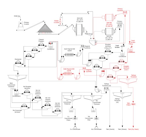
Initial Phase, Expansion Phase
|
17.3 Plant Description
17.3.1 Crushing and Material Handling
Run-of-mine (ROM) ore is delivered by rear-dump haul trucks (320 st capacity) directly to a primary crusher operating in open circuit. The trucks dump from either side of a two-sided dump pocket with a live capacity of 361 st. The crushing system operates in two distinct phases over the mine life:
• Years 1 - 4: A plant-side gyratory crusher (Sandvik CG850i) with installed power of 1300 HP handles a design feed rate of 3,333 stph.
• Year 5 onwards: An in-pit crusher (670 HP) with a nominal feed rate of 5,000 stph and a design rate of 6,500 stph will supplement the initial plant side gyratory crusher. Crushed ore will be transferred by a series of overland and aerial conveyors to the coarse ore stockpile feed conveyor.
For both arrangements, the design crusher runtime is 75%. The crushers reduce the ore from a design F80 of 15 inches (F100 of 39 inches) down to a product P80 of 6.0 inches.
17.3.1.1 Plant-Side Crusher (Years 1-4)
The plant-side crusher discharges by gravity into a surge pocket. From there, a variable speed apron feeder transfers the crushed ore directly onto the coarse ore stockpile feed conveyor, which delivers the material to the coarse ore stockpile which has a live capacity of 60,000 st, or 24 hours residence time.
17.3.1.2 In-Pit Crusher (Years 5+)
The in-pit crusher discharges into its own surge pocket, where a variable-speed apron feeder transfers the ore onto a short sacrificial conveyor. This conveyor feeds a network of overland and aerial conveyors to move the material to the plant:
The sacrificial conveyor feeds the first overland conveyor, which delivers ore to a first aerial conveyor running over Broad Top. At the northern end of the pit, material transfers through a chute to a second aerial conveyor spanning the west pit. This discharges through a chute to a second overland conveyor, which connects via another chute to a third overland conveyor. The system transfers ore to the stockpile feed conveyor.
17.3.1.3 Maintenance and Dust Control
Both crushing facilities include a rock breaker to handle oversize material. Dust suppression systems control emissions during dumping and crushing operations, and dedicated dust collectors are installed at all conveyor transfer points. Dust suppression sprays are used to minimize dust at the discharge point to the stockpile.
17.3.1.4 Major Equipment
Major equipment in the crushing and conveying circuits is summarized in Table 17-1.
|
Table 17-1: Major Equipment in the Crushing and Conveying Circuits
| Equipment | Phase | Installed Power (HP) |
| Primary Crusher 1 | Initial | 1,300 |
| Primary Crusher 1 Rock breaker | Initial | 150 |
| Primary Crusher 1 Discharge Feeder | Initial | 170 |
| Coarse Stockpile Feed Conveyor | Initial | 1,300 |
| Crusher Air Compressor | Initial | 250 |
| Coarse Stockpile Feed Conveyor | Expansion | 2,600 |
| In-pit Gyratory Crusher | Expansion | 2,000 |
| In-pit Apron Feeder | Expansion | 177 |
| In-pit Sacrificial Conveyor | Expansion | 402 |
| Overland Conveyor 1 | Expansion | 805 |
| Overland Conveyor 2 | Expansion | 402 |
| Overland Conveyor 3 | Expansion | 2,602 |
| Overland Conveyor 4 | Expansion | 805 |
| Aerial Conveyor 1 | Expansion | 2,124 |
| Aerial Conveyor 2 | Expansion | 2,124 |
| Process Plant Feed Conveyor | Expansion | 402 |
| Low-Grade Transfer Conveyor | Expansion | 402 |
| Low-Grade Tripper Conveyor | Expansion | 101 |
| Low-Grade Bypass Conveyor | Expansion | 248 |
17.3.2 Coarse Ore Stockpile
The stockpile feed conveyor transports the crushed ore to the coarse ore stockpile. The conveyor is fitted with a belt scale and belt monitoring systems. The coarse ore stockpile has a total capacity of 150,000 st and a live capacity of 60 kstpd. Prior to the plant expansion, crushed ore is withdrawn from the stockpile using two operating feeders and one standby reclaim apron feeder. During the expansion, a fourth feeder will be added to the circuit, bringing the configuration to three operating feeders and one standby feeder.
The reclaim feeders transfer the crushed ore onto the SAG mill feed conveyor, which is equipped with two belt scales and an integrated belt monitoring system.
17.3.2.1 Maintenance and Dust Control
The reclaim tunnel is equipped with a dust suppression system and a dust collector to mitigate airborne dust at the feeder discharge points. Additionally, the tunnel features an overhead trolley hoist to facilitate the servicing and removal of heavy apron feeder components.
17.3.2.2 Major Equipment
Major Equipment in the coarse ore stockpile area is summarized in Table 17-2.
|
Table 17-2: Major Equipment in the Coarse Ore Stockpile Area
| Equipment | Phase | Installed Power (HP) |
| Reclaim apron feeders 1 - 3 | Initial | 82 |
| Reclaim apron feeder 4 | Expansion | 82 |
17.3.3 Grinding and Classification
The initial grinding circuit consists of a 40 ft x 28 ft semi-autogenous grinding (SAG) mill, followed by a 40 ft x 26 ft ball mill arranged in a closed circuit with a cyclone cluster (SAB circuit). The nominal throughput of the grinding circuit is 2,720 st/h. The circuit reduces the reclaimed ore from an F80 of 6.0 inches to a final product P80 of 150 µm. To expand the plant throughput to 90 kstpd, a pebble crusher (converting the configuration to an SABC circuit) and a second 48 ft x 28 ft ball mill (also operating in closed circuit with a cyclone cluster) will be added during in the expansion phase, maintaining a target P80 of 150 µm.
The SAG mill utilizes a grate discharge configuration with pebble ports. The SAG mill product discharges onto a trommel and a vibrating screen deck, both with apertures of 0.6 inches. Steel grinding media is added to the SAG mill as required to maintain target throughput. The vibrating screen undersize gravitates directly to the cyclone feed pumpbox. In the initial phase, the vibrating screen oversize is conveyed directly back to the SAG mill feed conveyor. Following the expansion, this oversize material will be routed to the pebble crusher before returning to the circuit. The pebble crushing circuit will comprise two vibrating feeders, each feeding an 1100 HP cone crusher. The pebble stream can bypass the crushers to the SAG mill feed conveyor (or bypass bunker) if required via a diverter gate located ahead of the surge bin. In normal operation, pebbles pass through the diverter gate to the surge bin. Vibrating feeders are used to transfer pebbles from the surge bin to the pebble crushers. The pebble crusher discharge is transferred by conveyor to the SAG mill feed conveyor. A scale located on the transfer conveyor will monitor the SAG mill pebble recycle rate.
The SAG mill screen undersize constitutes fresh feed to the secondary grinding circuit. It discharges into a cyclone feed hopper where it combines with ball mill discharge prior to being pumped to the cyclone cluster(s). Process water is introduced to the cyclone feed hopper to control and maintain target slurry densities.
The cyclone underflow gravitates to the ball mill feed chute(s), while the cyclone overflow (P80 150 µm) passes through a linear trash screen and gravitates to the flotation feed conditioning tank. The overflow streams are sampled and analyzed by an inline analyzer and a particle size analyzer. During the initial phase of the project, the circuit is configured to allow a portion of the cyclone underflow to be diverted back to the SAG mill feed chute to balance power distribution between the mills. The ball mill circuit is designed for a nominal circulating load of 250% and a design maximum of 350%.
17.3.3.1 Maintenance and Operability
The circuit includes provisions for tramp metal removal, pebble bypass, and recycle rate monitoring. Dedicated instrumentation supports continuous particle size measurement and metallurgical sampling. System stability is maintained through coordinated mill and classification operations utilizing variable-speed drives, controlled slurry pumping, and flexible pipe routing. The initial layout accounts for the future expansion phase, and all maintenance systems are configured to minimize operational downtime.
|
17.3.3.2 Major Equipment
Major Equipment in the grinding and classification area is summarized in Table 17-3.
Table 17-3: Major Equipment in the Crushing and Conveying Circuits
| Equipment | Phase | Installed Power (HP) |
| SAG Mill: 40 ft diameter by 28 ft EGL | Initial | 37,550 |
| SAG Mill Feed Conveyor | Initial | 400 |
| SAG Mill Discharge Screen | Initial | 40 |
| SAG Mill Discharge Pump | Initial | 1,000 |
| Ball Mill 1 Cyclone Feed Pump | Initial | 4,000 |
| Ball Mill 1: 26 ft Diameter by 40 ft EGL | Initial | 22,000 |
| Pebble Conveyor 1 | Initial | 30 |
| Pebble Conveyor 2 | Initial | 250 |
| Ball Mill 2 Cyclone Feed Pump | Expansion | 5,360 |
| Ball Mill 2: 28 ft Diameter by 48 ft EGL | Expansion | 32,200 |
| Pebble Crusher 1 & 2 | Expansion | 1,100 |
| Pebble Conveyor 2 Expansion | Expansion | 250 |
| Primary Grinding Cyclone Cluster 2 O/F Pump 1 & 2, per unit | Expansion | 900 |
| Primary Grinding Cyclone Cluster 2 O/F Pump 2 | Expansion | 800 |
17.3.4 Bulk Flotation
The cyclone overflow will gravitate to the rougher flotation feed diverter box that splits the stream to two rougher flotation lines. The split streams will pass through dewatering trash screens and report to the bulk rougher conditioning tanks (one per line) where collector, frother and sulfurization reagents (NaHS) will be added. During the processing of high pyrite content ore, lime may also be added to the rougher conditioning tanks as a depressant. Reagent addition points are also included in the pump boxes of the rougher flotation cells. The conditioned slurry is then pumped to the Jameson Cells to undergo flotation to concentrate molybdenum and copper with silver and gold in the bulk concentrate. Initially, the bulk rougher flotation circuit consists of two trains of three Jameson Cells (Model B8500/12, 27.9 ft diameter). The expansion will require an additional conditioning tank and a third train of three Jameson rougher flotation cells (Model B8500/12), expanding the capacity of the circuit to 90 kstpd. Concentrate from all lines will be combined inline and will report to the bulk rougher concentrate hopper via a metallurgical sampler and analyzer. Flexible valve and piping arrangements will allow for the first cell in the roughing circuit to act as a scalping cell. Concentrate from the rougher scalper will report to either a) the first cleaner cell (enabling it to act as a 'coarse cleaner', with tails fed back to the regrind mill), or b) directly to final concentrate.
The combined rougher concentrate is pumped to a regrind mill (M20000 IsaMill, 6,700 HP) configured in an open circuit with cyclones ahead of the mill to remove minus 32 µm particles, with the cyclone underflow discharging to the IsaMill feed hopper. Water will be added to the IsaMill feed hopper to maintain the feed below 20 % solids w/v. The bulk concentrate regrind circuit will produce a product P80 32 µm prior to upgrading in the cleaner circuit. In the Extension Case, an additional fine grinding mill (M10000 IsaMill, 4,020 HP) will be added to the circuit.
|
The bulk regrind product is combined with bulk regrind cyclone overflow and is pumped to the cleaner flotation conditioning tank for the addition of collector, pH modifiers, and frother. During the processing of high pyrite content ore, lime and cyanide may be added to the cleaner conditioning tank as depressants. The bulk cleaner flotation circuit consists of four (4) Jameson flotation cells (Model B6500/24, 21.3 ft diameter), comprising three cleaner cells in series and a recleaner. Cleaner 1 will be configured to run as the first cleaner, or as a cleaner scalper.
When in scalping mode the concentrate from the first cleaning cell will report to final concentrate via an inline metallurgical sampler, with tails reporting to the Cleaner 2 feed pump hopper. The concentrate from Cleaner 2 will report to the recleaner, while the tails report to the cleaner scavenger for scavenging of the residual copper, molybdenum, silver, and gold. The concentrate from the cleaner scavenger will report back to Cleaner 2. The recleaner will produce final concentrate, targeting a grade of 25 % w/w copper, with the tails also returning to Cleaner 2.
When configured as the first cleaning stage the Cleaner 1 concentrate will report to the recleaner, and tails to Cleaner 2. Cleaner 2 concentrate will also report to the recleaner, with tails reporting to the cleaner scavenger. The cleaner scavenger concentrate will report to the cleaner conditioning tank. Similarly to above, the recleaner will produce final concentrate, targeting a grade of 25 % w/w copper, with the tails returned to Cleaner 2.
Cleaner scavenger tails piping will allow the circuit to be reconfigured to direct cleaner tails back to the second rougher cell (instead of final tails) when conditions may require improved recovery of slower floating minerals.
The bulk rougher tailings streams from each rougher line are combined with bulk cleaner circuit final tailings and gravitate to the final tailings tank through a metallurgical sampler.
17.3.4.1 Major Equipment
The major equipment in the Bulk Flotation area is summarized in Table 17-4.
Table 17-4: Major Equipment in Bulk Flotation Area
| Equipment | Phase | Installed Power (HP) |
| Roughing Circuit | ||
| Bulk Rougher Flotation Conditioning Tank 1 & 2, per unit | Initial | 50 |
| Jameson Cell 1 - 3 (model B8500/12), Line 1 | Initial | - |
| Jameson Cell 1 - 3 (model B8500/12), Line 2 | Initial | - |
| Jameson Cell Feed Pump 1, Lines 1 & 2, per unit | Initial | 1250 |
| Jameson Cell Feed Pump 2, Lines 1 & 2, per unit | Initial | 1000 |
| Jameson Cell Feed Pump 3, Lines 1 & 2, per unit | Initial | 900 |
| Bulk Rougher Concentrate Pump | Initial | 600 |
| Flotation Tailings Pump 1 - 3, per unit | Initial | 1000 |
| Bulk Rougher Flotation Conditioning Tank 3 | Expansion | 74 |
| Jameson Cell 1 - 3 (model B8500/12), Line 3 | Expansion | - |
| Jameson Cell Feed Pump 1, Line 3 | Expansion | 900 |
| Jameson Cell Feed Pump 2, Line 3 | Expansion | 900 |
| Jameson Cell Feed Pump 3, Line 3 | Expansion | 800 |
| Bulk Rougher Concentrate Pump, Line 3 | Expansion | 200 |
|
| Equipment | Phase | Installed Power (HP) |
| Bulk Rougher Tailings Pump, Line 3 | Expansion | 900 |
| Regrind | ||
| Regrind IsaMill 1 (M20000) | Initial | 6700 |
| Regrind IsaMill 2 (M10000) | Expansion | 4020 |
| Cleaning Circuit | ||
| Cleaner Conditioning Tank | Initial | 15 |
| Jameson Cleaner Cells 1 - 4, | Initial | - |
| Cleaner Scalper Flotation Cell feed Pump | Initial | 500 |
| Cleaner Flotation Cell 2 Feed Pump | Initial | 700 |
| Cleaner Flotation Cell 2 Feed Pump | Initial | 150 |
| Cleaner Scavenger Flotation Cell feed Pump | Initial | 700 |
| Bulk Cu-Mo Concentrate Pump | Initial | 75 |
| Cleaner Tailings Pump | Initial | 250 |
| Cleaner Scalper Tailings Pump | Initial | 400 |
17.3.5 Bulk Concentrate Thickening
The bulk concentrate is pumped to the Cu-Mo concentrate thickener feed box, through a trash screen and deaeration tank. The bulk concentrate is thickened in a single 79 ft diameter high-rate thickener with the aid of flocculant. The underflow from the bulk concentrate thickener will be approximately 60% solids w/w. Clarified thickener overflow from the Cu-Mo concentrate thickener reports to the thickener overflow tank and is pumped to the process water tank. The underflow of the Cu-Mo concentrate thickener is pumped to the molybdenum flotation circuit.
17.3.5.1 Major Equipment
The major equipment in the Bulk Concentrate Thickening area is summarized in Table 17-5.
Table 17-5: Major Equipment in Bulk Thickening Area
| Equipment | Phase | Installed Power (HP) |
| Cu-Mo Concentrate Thickener | Initial | 17 |
| Cu-Mo Thickener Underflow, Pumps 1 & 2, each | Initial | 15 |
17.3.6 Molybdenum Flotation
The bulk concentrate thickener underflow will be pumped to the molybdenum rougher conditioning tanks (two tanks in series), where sodium hydrosulfide and carbon dioxide will be added to suppress the copper minerals. Fuel Oil (as a collector), dispersant and frother will also be added.
The conditioned slurry will undergo flotation for selective recovery of molybdenum from the bulk concentrate. All flotation cells in the molybdenum circuit are Jameson flotation cells. The molybdenum flotation circuit consists of a single train with one rougher and one scavenger flotation cell (Jameson Cell Model E2514/3). After rougher flotation, the molybdenum concentrate passes through a scrubber to remove the gases before going to the molybdenum cleaner conditioning tank where fuel oil (collector), dispersant, CO2 and sodium hydrosulfide are added. The conditioned rougher concentrate then progresses to three stages of cleaner flotation. The cleaning flotation circuit comprises one Jameson Cell per cleaning stage (Jameson Cell Model Z1200/1) to produce a molybdenum concentrate that is 50 % Mo by weight. The rougher products, and products from each stage of cleaning, will be sampled and analysed in a multi-stream slurry analyzer. The final molybdenum concentrate reports to the molybdenum thickener. The tailings from the molybdenum roughers will be pumped to the copper thickener. The overflow from the molybdenum thickener reports to the molybdenum process water tank for return to the molybdenum flotation circuit.
|
17.3.6.1 Major Equipment
Major Equipment in the Molybdenum Flotation area is summarized in Table 17-6.
Table 17-6: Major Equipment in Molybdenum Flotation Area
| Equipment | Phase | Installed Power (HP) |
| Roughing Circuit | ||
| Molybdenum Rougher Conditioning Tanks 1 & 2, per unit | Initial | 8 |
| Molybdenum Rougher Circuit Jameson Cells 1 - 2 (Model E2514/3) | Initial | - |
| Molybdenum Rougher Cell Feed Pumps 1 & 2, per unit | Initial | 60 |
| Cleaning Circuit | ||
| Molybdenum Cleaner Conditioning Tank | Initial | 3 |
| Molybdenum Cleaner Jameson Cells 1 - 3 (Model Z1200/1) | Initial | - |
| Molybdenum Cleaner Cell 1 Feed Pump | Initial | 25 |
| Molybdenum Cleaner Cell 2 Feed Pump | Initial | 20 |
| Molybdenum Cleaner Cell 3 Feed Pump | Initial | 15 |
| Molybdenum Cleaner Tails Pump | Initial | 20 |
17.3.7 Copper Concentrate Dewatering
The copper concentrate (tailings from the molybdenum flotation circuit) will be pumped to a single high-rate thickener 79 ft in diameter, via a metallurgical sampler. The thickener overflow water will be recycled to the bulk and molybdenum flotation circuits. The copper concentrate thickener underflow will be pumped to an agitated concentrate stock tank, via a trash screen, prior to filtration. The initial installation will include two copper concentrate pressure filters, with a third pressure filter added during the expansion. The final filtration cake design moisture is 10%. Raw water is used for filter cloth washing. Process water is used to flush the filter manifolds. Filtrate reports to the copper filtrate tank and is then pumped back to the copper concentrate thickener. The copper concentrate will be discharged by gravity into a stockpile, from which front-end loaders will load into concentrate storage bays ahead of the concentrate leach process, or prior to sale to a third party. Copper concentrate sold to a third party will be loaded by FEL into covered containers on highway haulage trucks for transport from the mine site to the storage terminal at the Tucson rail facility.
17.3.7.1 Major Equipment
Major Equipment in the Copper Concentrate Dewatering area is summarized in Table 17-7.
|
Table 17-7: Major Equipment in Copper Concentrate Dewatering Area
| Equipment | Phase | Installed Power (HP) |
| Copper Concentrate Thickener | Initial | 17 |
| Copper Thickener Overflow Transfer Pump 1 & 2 | Initial | 125 |
| Copper Filter Feed Tank 1 & 2, per unit | Initial | 61 |
| Copper Filter Pressing Air Compressor 1 & 2, per unit | Initial | 200 |
| Copper Filter Drying Air Compressor 1 & 2, per unit | Initial | 200 |
| Copper Filter Feed Pump 1 - 3, per unit | Initial | 215 |
| Copper Concentrate Filter 1 & 2 | Initial | 40 |
| Copper Filtrate Pump 1 & 2, per unit | Initial | 215 |
| Copper Filter Pressing Air Compressor 3 | Expansion | 150 |
| Copper Filter Drying Air Compressor 3 | Expansion | 430 |
| Copper Filter Feed Tank 3 | Expansion | 60 |
| Copper Filter Feed Pump 4 | Expansion | 215 |
| Copper Concentrate Filter 3 | Expansion | 40 |
| Copper Filtrate Pump 3 | Expansion | 215 |
17.3.8 Molybdenum Concentrate Dewatering
The molybdenum concentrate will be pumped from the third molybdenum cleaner cell to the molybdenum concentrate thickener feed box, through a metallurgical sampler and analyzer, before progressing to a 20 ft diameter high-rate thickener. The thickener overflow water will be returned as process water to the molybdenum flotation circuit. The molybdenum concentrate thickener underflow will be pumped to an agitated filter feed tank via a trash screen prior to the filtration process. The concentrate will be filtered in a pressure filter, targeting a cake design moisture of 15%. Raw water is used for filter cloth washing, filter manifold flushing, and plate membrane inflation. Filtrate, cloth wash, plate membrane water and manifold flushing waters are collected and pumped back to the molybdenum concentrate thickener. The molybdenum filter cake is discharged from the filter through a cake breaker onto the drier belt feeder and directed to the dryer feedbox. The concentrate is then further dried in a dryer, which is equipped with a thermal oil heater, off-gas scrubber, electrostatic precipitator and vent stack, to a final cake moisture of 5%. Dried concentrate is stored in a bin before being bagged in 2 st bulk bags in the bagging station. Bagged concentrate is then weighed and labelled prior to being loaded onto trucks by forklift for transport, to be sold to a third party.
17.3.8.1 Major Equipment
The major equipment in the Molybdenum Concentrate Dewatering area is summarized in Table 17-8.
Table 17-8: Major Equipment in Molybdenum Concentrate Dewatering Area
| Equipment | Phase | Installed Power (HP) |
| Molybdenum Concentrate Thickener (20 ft diameter) | Initial | 4 |
| Molybdenum Filter Feed Tank | Initial | 8 |
| Molybdenum Concentrate Filter | Initial | 31 |
| Molybdenum Filter Drying Air Compressor 1 & 2, per unit | Initial | 40 |
| Molybdenum Dryer | Initial | 3 |
| Molybdenum Bagging System | Initial | 15 |
|
17.3.9 Tailings
The combined tailings from the concentrator are pumped to the tailings hydrocyclones for sands slime separation, where the flotation tailings will undergo cyclone classification to generate a fines deficient sands stream suitable for constructing the tailings storage facility embankments. The fines deficient cyclone underflow (sands) is pumped to the cyclone sands distribution box prior to being pumped for placement on the tailing's storage facility embankments. The tailings cyclone underflow from cyclones 1 and 2 are collected in a hopper while the underflow from cyclone 3 is collected in a transfer pump box and then both report to the distribution box. A cyclone sands distribution box will redirect one third of the sands to tailings filtration (further described below).
The fine tailings hydrocyclone overflow reports to a thickener feed distributor, which splits the slurry among multiple thickeners for further dewatering. If the concentrate leaching facility is installed, residue from the iron control stage in the concentrate leach plant will be combined with the hydrocyclone overflow and report to the thickener feed distributor. Initially the circuit will include three 164 ft diameter high-density thickeners, each with a dedicated cyclone cluster. The thickener overflow reports to the process water tank. The underflow from each thickener will be pumped to the tailings thickener underflow distribution box from which it will be pumped to the tailings storage facility by two trains of centrifugal pumps (three pumps operating in series initially, five pumps operating in series after the expansion).
The expansion to 90 kstpd will include filtration of a portion of thickened tails, with an additional 164 ft thickener and four filters added to accommodate this. Underflow from the original three thickeners will be pumped to a tailings slime diverter box, which will direct one third of the slimes to a tailings filter feed plant tank. The sands from the four tailings cyclones underflow streams will report to a tailings sand diverter box where they will be combined, and one third of the tailings sands also sent to the tailings filter feed plant tank to be combined with the tailings slimes. The combined tailings sands and slimes will then be pumped to the fourth 164 ft diameter tailings filter plant thickener. The underflow from this thickener is pumped to an agitated tailings slurry feed tank, before being pumped to four filter presses (3 duty, 1 standby) to produce a filter cake targeting 14 % moisture. The filtrate is recovered and pumped back to the thickener with the thickener overflow gravitating into an overflow tank before being pumped back to the process water tank at the concentrator. The filter cake is conveyed out of the filtration building onto grasshopper conveyors before it is stacked using radial stackers.
17.3.9.1 Major Equipment
The major equipment in the tailings area is summarized in Table 17-9.
Table 17-9: Major Equipment in Tailings Area
| Equipment | Phase | Installed Power (HP) |
| Tailings Cyclone Clusters 1 - 3 | Initial | - |
| Tailings Thickeners 1 - 3, 50 m diameter, per unit | Initial | 172 |
| Thickener 1 - 3 Underflow Pumps 1 and 2, per unit | Initial | 300 |
| Slimes Tailings Pumps, Train A and B, Pumps 1 - 4, per unit | Initial | 900 |
| Cyclone Sand Pumps 1 - 3 | Initial | 2680 |
| Cyclone Sands Charge Pumps | Initial | 100 |
| Tailings Reclaim Water Pumps 1 - 3, per unit | Initial | 1250 |
| Tailings Reclaim Water Pumps 4 & 5, per unit | Initial | 800 |
|
| Equipment | Phase | Installed Power (HP) |
| Process Water Pumps 1 - 3, per unit | Initial | 1250 |
| Slimes Tailings Pumps, Train A and B, Pumps 5, per unit | Expansion | 900 |
| Tailings Filter Plant Thickener, 50 m diameter | Expansion | 172 |
| Tailings Filter Plant Thickener Underflow Pump | Expansion | 300 |
| Tailings Slurry Feed Pump 1 - 4 | Expansion | 845 |
| Tailings Filter Press + Hydraulic Unit 1 - 4, per unit | Expansion | 207 |
| Tailings Filter Press Discharge Unit 1 - 4, per unit | Expansion | 201 |
| Process Water Pump 4 | Expansion | 1250 |
17.3.10 Reagents and Consumables
Various chemical reagents will be added to the processing circuit to modify the mineral particle, to either enhance mineral floatability or chemically break them down and extract the contained elements to the solution phase. The reagents onsite will be prepared and stored in separate, self-contained areas inside the process plant.
17.3.10.1 Concentrator
17.3.10.1.1 Collectors
Collectors will be delivered to site as liquids in bulk 20-ton road tankers at a concentration of 30% w/w and pumped into an insulated storage tank. The concentrated collectors are then transferred from the bulk storage tank in batches to a mixing tank where they are diluted to 10% w/w with fresh water. A second transfer pump is used to transfer the collectors to the day tank, from where they are dosed to the bulk flotation circuit via metering pumps with flow measuring units.
Fuel Oil in liquid form will be delivered to site in bulk 20-ton road tankers and transferred into a bulk storage tank. Fuel Oil is transferred from the bulk storage tank in batches to two tanks, each with two days residence time, one tank will feed the bulk flotation circuit and the other will feed the molybdenum flotation circuit. Fuel Oil will be dosed to the flotation circuits via metering pumps with flow measuring units.
During the expansion additional metering pumps will be added to deliver SIBX and thionocarbamate to the third line of rougher flotation cells.
17.3.10.1.2 Frothers
Frothers will be received as a liquid and transferred to a bulk storage tank and used at the supplied solution strength and dosed to the flotation circuits (bulk flotation and molybdenum flotation) via metering pumps with flow measuring units.
During the expansion additional metering pumps will be added to deliver frother to the third line of rougher flotation cells.
|
17.3.10.1.3 Sodium Hydrosulfide
Sodium hydrosulfide (NaHS) will be delivered to site in bulk 24-ton road tankers at a concentration of 45% w/w and transferred to a bulk storage tank. The bulk storage tank is insulated to prevent the concentrated solution from freezing. NaHS solution is transferred from the bulk storage tank to a holding tank via an in-line mixer where it is diluted to 15% w/w with fresh water. Vapor from NaHS storage tank is vented to the atmosphere via a caustic scrubber to remove hydrogen sulfide (H2S). Metering pumps complete with flow measuring units will deliver the NaHS to the bulk and molybdenum flotation circuits. During the expansion additional metering pumps will be added to deliver NaHS to the third line of rougher flotation cells.
17.3.10.1.4 Dispersant
Dispersant (NS1162) will be delivered as a liquid in bulk 22.5-ton road tankers and pumped into the bulk storage tank. The dispersant will be used at the supplied solution strength. The dispersant will be transferred to a distribution day tank from which it will be dosed to the bulk cleaner and molybdenum flotation circuits via metering pumps complete with flow measuring units.
17.3.10.1.5 Depressant
Depressant (sodium cyanide) is delivered to site as solid briquettes in one-ton bulk bags. The briquettes are dissolved in fresh water in a dedicated storage tank to produce a dilute solution suitable for dosing. The prepared solution is transferred to a holding tank from which metering pumps deliver the required dosage to the bulk cleaning circuit.
17.3.10.1.6 Flocculant
Flocculant will be delivered as a dry powder in one-ton bags and stored in a covered building. The flocculant powder is transferred to a heated hopper and blown into the wetting head to produce a 0.25% w/w flocculant solution. The flocculant solution is mixed in an agitated tank and transferred to a storage tank prior. The solution is then dosed by dedicated dosing pumps to respective thickener feed boxes through inline mixers. Individual flocculant mixing systems are used to provide flocculant for the flotation tailings thickeners, concentrate thickeners, sulfur removal and iron removal thickener. During the expansion additional metering pumps will be added to deliver flocculant to the fourth thickener.
17.3.10.1.7 Quicklime
The quicklime will be delivered as a coarse powder in standard 26-ton bulk road transport carriers, and unloaded pneumatically into a storage silo at the lime slaking plant. Quicklime is slaked with fresh water in a ball mill to produce milk of lime slurry. The discharged slurry is pumped to a cyclone to remove grit. Cyclone underflow returns to the mill, while the overflow at 20% w/w solids gravitates to an agitated storage tank. A lime circulating pump and pressurized ring main delivers lime slurry to the bulk rougher and cleaner circuit conditioning tanks and dosing points in the lime boil and bleed treatment circuits of the concentrate leach plant. Pinch valves are used to control lime addition at each dosing point.
|
17.3.11 Water Supply
Fresh water will be sourced from wells located on the western side of the Santa Rita Mountains and will be pumped through a series of pumps to the freshwater tank. From the storage tank, water will be pumped around the plant for use in reagent mixing, slurry pump gland seals and as required for mill lubrication system cooling.
Process water will be sourced from the tailings and concentrate thickener overflows, tailings storage facility reclaim and seepage ponds, and from the freshwater tank as required. Process water will be stored in the process water pond. Process water pond pumps transfer water from the storage pond to the process water tank. Excess water in the process water tank overflows back to the process water pond.
The tailings thickener overflow streams will discharge directly to the process water tank for immediate distribution and use.
Water supply is discussed in greater detail in section 18.
17.3.12 Air Supply
Three separate plant air compressors will provide air service throughout the process plant. The instrument air will be dried using a refrigeration drier and stored in a dedicated receivers distributed throughout the plant. The plant air will be fed directly to dedicated plant air receivers distributed throughout the plant.
Each filtration stage in the processing plant will come with a dedicated high pressure air supply and receiver.
All flotation cells in the process plant are self-aspirated and no air is required for this duty.
17.3.13 Assay Laboratory
The assay laboratory will be provided by a third party onsite under contract to provide all required assay analytical services required by both mine and process plant.
17.4 Process Design Criteria
The Copper World flowsheet produces copper concentrate and molybdenum concentrate. Where economically justified, future expansion capabilities from 60 kstpd to 90 kstpd are incorporated into the initial design (Table 14-10). Although this increases upfront CAPEX beyond what is strictly required for the processing of 60 kstpd of ore, it maximises economic performance of the project over the life of the mine.
Table 17-11 provides a summary of the planned comminution (crushing and grinding) circuit). The sulfide concentrator and concentrate dewatering design summary are provided in Table 17-12 and Table 17-13, respectively.
|
Table 17-10: Process Design Criteria Overview - Concentrator
| Criteria | Unit | Initial | Expansion |
| Plant Design Capacity | st/a | 21,900,000 | 32,850,000 |
| st/d | 60,000 | 90,000 | |
| st/h | 2,720 | 4,076 | |
| Operating Availability | |||
| Crushing | % | 75 | 75 |
| Grinding | % | 92 | 92 |
| Copper and Molybdenum Flotation | % | 92 | 92 |
| Tailings | % | 92 | 92 |
| Concentrate Dewatering | % | 85 | 85 |
| ROM Specific Gravity | |||
| Range | - | 2.7 - 2.9 | 2.7 - 2.9 |
| Nominal for Design | - | 2.84 | 2.84 |
| ROM Moisture, % H2O | |||
| Range | % w/w | 2 - 5 | 2 - 5 |
| Nominal for Design | % w/w | 4 | 4 |
| Bulk Density | t/m3 | 1.84 | 1.84 |
| Plant Ore Feed Grades - Design Max | |||
| Copper - Total | % w/w | 0.89 | 0.89 |
| Copper - Acid Soluble | % w/w | 0.20 | 0.20 |
| Copper - Sulfide | % w/w | 0.84 | 0.84 |
| Molybdenum | % w/w | 0.14 | 0.14 |
| Plant Ore Feed Grades - LOM Average | |||
| Copper - Total | % w/w | 0.50 | 0.50 |
| Copper - Acid Soluble | % w/w | 0.12 | 0.12 |
| Copper - Sulfide | % w/w | 0.39 | 0.39 |
| Molybdenum | % w/w | 0.01 | 0.01 |
Table 17-11: Sulfide Concentrator Comminution Design Criteria
| Criteria | Unit | Peach-Elgin | West | Broad Top | East |
| Ore Hardness Characteristics | |||||
| SPI / SGI | |||||
| Mean | Min | 48 | 51 | 97 | 97 |
| 75th Percentile | Min | 65 | 69 | 113 | 141 |
| Axb | |||||
| Mean | - | 65.6 | 63.0 | 41.2 | 41 |
| 75th Percentile | - | 69 | 51.6 | 37.3 | 32 |
| BWi | |||||
| Mean | kWh/st | 10.9 | 12.6 | 11.6 | 11.7 |
| 75th Percentile | kWh/st | 12.2 | 13.3 | 12.3 | 13.6 |
| Ai | |||||
| Mean | g | 0.19 | 0.11 | 0.38 | 0.20 |
| 75th Percentile | g | 0.24 | 0.32 | 0.45 | 0.35 |
| Criteria | Unit | Value | |||
| Crushing (Single Stage) | |||||
| Primary Crusher | Type | Gyratory Crusher | |||
| Crushing Feed Size, F80 | Inch | 15 | |||
| Crushing Circuit Product, P80 | Inch | 6 | |||
| Grinding Plant Capacity | |||||
|
| Circuit Configuration | Type | SAB (SABC Year 5 onwards) |
| Circuit Capacity, Design (dry) | st/h | 60,000 stpa Initial 90,000 stpa Expansion |
| Feed Particle Size, F80 | inch | 2.5 - 4.0 |
| Product Particle Size, P80 | µm | 150 |
| Semi-Autogenous Mill (SAG) | ||
| SAG mill size | ft | 40 x 28 |
| Discharge Solids density | % w/w | 70 |
| SAG Power Index, Design | Min | 121 |
| SAG Mill Speed, % of Critical | ||
| Maximum | % | 80 |
| Typical | % | 75 |
| Minimum | % | 62 |
| SAG Mill Total Charge (max) | % | 35 |
| Pebble Crusher (Expansion) | ||
| Type | - | Cone Crusher |
| Number | # | 2 |
| Pebble Recycle Rate, Design | % | 20 |
| Crusher Feed Size, F100 | inch | 1.97 |
| Crusher Feed Size, F80 | inch | 1.91 |
| Crusher Product Size, P80 | inch | 0.50 |
| Ball Mill 1 (Initial) | ||
| Type | - | Overflow |
| Ball Mill Size | ft | 26 x 40 |
| Circuit Configuration | - | Closed |
| Ball Mill Circuit P80 | µm | 150 |
| Ball Mill Discharge Solids Density | % solids (w/w) | 70 - 75 |
| Circulating Load, nominal | % | 270 |
| Circulating Load, design | % | 350 |
| Ball Mill Speed, % of Critical | % | 75 |
| Ball Mill Charge | ||
| Normal Operating | % v/v | 27 - 31 |
| Maximum | % v/v | 32 |
| Ball Mill Discharge Screen | ||
| Screen Type | - | Trommel |
| Aperture Type | - | Slotted |
| Aperture Size | inch | 5/16 |
| Ball Mill 2 (Expansion) | ||
| Type | - | Overflow |
| Ball Mill Size | ft | 28 x 48 |
| Circuit Configuration | - | Closed |
| Ball Mill Circuit P80 | µm | 150 |
| Ball Mill Discharge Solids Density | % solids (w/w) | 70 - 75 |
| Circulating Load, nominal | % | 270 |
| Circulating Load, design | % | 350 |
| Ball Mill Speed, % of Critical | % | 75 |
| Ball Mill Charge | ||
| Normal Operating | % v/v | 27 - 31 |
| Maximum | % v/v | 32 |
| Ball Mill Discharge Screen | ||
| Screen Type | - | Trommel |
|
| Aperture Type | - | Slotted |
| Aperture Size | inch | 5/16 |
| Classification Cyclones | ||
| Hydrocyclone, Cluster per Ball Mill | - | 1 |
| Feed Solids Density | % solids (w/w) | 55 |
| Overflow Density | % solids (w/w) | 30 |
| Underflow Density | % solids (w/w) | 72 |
Table 17-12: Sulfide Concentrator Flotation Design Criteria
| Criteria | Unit | Initial | Expansion |
| Bulk Flotation - Rougher | |||
| Feed | |||
| Feed Rate | st/hr | 2,720 | 4,076 |
| Solids Density | % solids (w/w) | 30 | 30 |
| Solids pH | 8 | 8 | |
| Cells | |||
| Cell Type | Type | Jameson Cells | Jameson Cells |
| # of Lines | # | 2 | 3 |
| Number of Cells per Line | # | 3 | 3 |
| Flotation Cell Size | - | B8500/12 | B8500/12 |
| Stage Recovery to Rougher Concentrate | |||
| Mass, design | % | 12 | 8 |
| Concentrate Solids Density, nominal | % solids (w/w) | 25 | 25 |
| Bulk Regrind Mill | |||
| Mill Type | Type | IsaMill | IsaMill |
| # of Mills | # | 1 | 2 |
| Mill - Size | - | M20 000 | M20000 M10000 |
| Mill - Installed Power | HP | 5,500 | 5,500 3,000 |
| Feed Particle Size, F80 | µm | 70 | 70 |
| Product Particle Size, P80 | µm | 32 | 32 |
| Specific Grinding Energy | kWh/st | 6.6 | 6.6 |
| Bulk Cleaner Flotation | |||
| Feed | |||
| Feed Rate | st/hr | 326 | 326 |
| Solids Density | % solids (w/w) | 25 | 25 |
| Solids pH | 8 - 11 | 8 | |
| Global Recovery to Bulk Concentrate | |||
| Mass | % | 1.0 | 1.0 |
| Copper (Total) | % | 72 | 72 |
| Copper (Sulfide) | % | 88 | 88 |
| Copper (Acid Soluble) | % | 27 | 27 |
| Silver | % | 55 | 55 |
| Molybdenum | % | 42 | 42 |
| Cleaner Scalper | |||
| Solids Density | % solids (w/w) | 20 | 20 |
| Solids pH | - | 8 - 11 | 8 |
| Cells | |||
| Cell Type | Type | Jameson Cells | Jameson Cells |
| Number of Cells | # | 1 | 1 |
|
| Flotation Cell Size | - | B6500/24 | B6500/24 |
| Stage Mass Recovery, design | % | 1.5 | 1.5 |
| Concentrate Grade, Copper | % | 24 | 24 |
| Concentrate SG | 4.1 | 4.1 | |
| Concentrate Solids Density, nominal | % solids (w/w) | 25 | 25 |
| Cleaner 1 | |||
| Cell Type | Type | Jameson Cells | Jameson Cells |
| Number of Cells | # | 1 | 1 |
| Cell Size | - | B6500/24 | B6500/24 |
| Stage Mass Recovery, design | % | 15 | 15 |
| Concentrate Grade, Copper | % | 12 - 15 | 12 - 15 |
| Concentrate SG | 3.9 | 3.9 | |
| Concentrate Solids Density, nominal | % solids (w/w) | 25 | 25 |
| Cleaner 2 | |||
| Cells | |||
| Cell Type | Type | Jameson Cells | Jameson Cells |
| Number of Cells | # | 1 | 1 |
| Cell Size | - | B6500/24 | B6500/24 |
| Stage Mass Recovery, design | % | 16 | 16 |
| Concentrate Grade, Copper | % | 24 | 24 |
| Concentrate SG | 4.1 | 4.1 | |
| Concentrate Solids Density, nominal | % solids (w/w) | 25 | 25 |
| Cleaner Scavenger | |||
| Cells | |||
| Cell Type | Type | Jameson Cells | Jameson Cells |
| Number of Cells | # | 1 | 1 |
| Cell Size | - | B6500/24 | B6500/24 |
| Stage Mass Recovery, design | % | 4.0 | 4.0 |
| Concentrate Grade, Copper | % | 4.0 | 4.0 |
| Concentrate SG | 3.9 | 3.9 | |
| Concentrate Solids Density, nominal | % solids (w/w) | 18 | 18 |
| Molybdenum Flotation | |||
| Feed | |||
| Solids pH | - | 9 - 10 | 9 - 10 |
| Mo Recovery to Concentrate, Design | % | 92 | 92 |
| Rougher | |||
| Feed Solids Density, Design | % | 28 | 28 |
| Cells | |||
| Cell Type | Type | Jameson Cells | Jameson Cells |
| Number of Cells | # | 1 | 1 |
| Cell Size | - | E2514/3 | E2514/3 |
| Stage Mass Recovery, design | % | 6.7 | 6.7 |
| Concentrate SG | 4 | 4 | |
| Concentrate Solids Density, nominal | % solids (w/w) | 26 | 26 |
| Scavenger | |||
| Feed Solids Density, Design | % solids (w/w) | 25 | 25 |
| Cells | |||
| Cell Type | Type | Jameson Cells | Jameson Cells |
| Number of Cells | # | 1 | 1 |
| Cell Size | - | E2514/3 | E2514/3 |
| Stage Mass Recovery, design | % | 5 | 5 |
|
| Concentrate SG | 4.0 | 4.0 | |
| Concentrate Solids Density, nominal | % solids (w/w) | 25 | 25 |
| Cleaner 1 | |||
| Feed Solids Density, Design | % solids (w/w) | 25 | 25 |
| Cells | |||
| Cell Type | Type | Jameson Cells | Jameson Cells |
| Number of Cells | # | 1 | 1 |
| Cell Size | - | Z1200/1 | Z1200/1 |
| Stage Mass Recovery, design | % | 34 | 34 |
| Concentrate SG | 4.0 | 4.0 | |
| Concentrate Solids Density, nominal | % solids (w/w) | 25 | 25 |
| Cleaner 2 | |||
| Cells | |||
| Cell Type | Type | Jameson Cells | Jameson Cells |
| Number of Cells | # | 1 | 1 |
| Cell Size | - | Z1200/1 | Z1200/1 |
| Stage Mass Recovery, design | % | 38 | 38 |
| Concentrate SG | 4.0 | 4.0 | |
| Concentrate Solids Density, nominal | % solids (w/w) | 25 | 25 |
| Cleaner 3 | |||
| Cells | |||
| Cell Type | Type | Jameson Cells | Jameson Cells |
| Number of Cells | # | 1 | 1 |
| Cell Size | - | Z1200/1 | Z1200/1 |
| Stage Mass Recovery, design | % | 53 | 53 |
| Concentrate Grade, Molybdenum | % | 50 | 50 |
| Concentrate SG | - | 4.0 | 4.0 |
| Concentrate Solids Density, nominal | % solids (w/w) | 25 | 25 |
Table 17-13: Sulfide Concentrator Concentrate Dewatering Design Criteria
| Criteria | Unit | Initial | Expansion |
| Bulk Concentrate Thickener | |||
| Number of Units | # | 1 | 1 |
| Type | - | High-Rate | High-Rate |
| Diameter | ft | 79 | 79 |
| Unit Area for Thickening Rate, Design | st/ft2/hr | 0.03 | 0.03 |
| Thickener Underflow Density, Design | % Solids (w/w) | 60 | 60 |
| Copper Concentrate Thickener | |||
| Number of Units | # | 1 | 1 |
| Type | - | High-Rate | High-Rate |
| Diameter | ft | 79 | 79 |
| Unit Area for Thickening Rate, Design | st/ft2/hr | 0.03 | 0.03 |
| Thickener Underflow Density, Design | % Solids (w/w) | 60 | 60 |
| Copper Concentrate Filtration | |||
| Number of Units | # | 2 | 3 |
| Type | - | Pressure | Pressure |
| Filtration Rate, Design | lb/ft2/h | 82 | 82 |
| Nominal Filter Cake Moisture | % (w/w) | 10 | 10 |
| Specific Gravity | - | 4.1 | 4.1 |
| Molybdenum Concentrate Thickener | |||
| Number of Units | # | 1 | 1 |
|
| Type | High-Rate | High-Rate | |
| Diameter | ft | 13 | 13 |
| Unit Area for Thickening Rate, Design | st/ft2/hr | 0.25 | 0.25 |
| Feed Solids Density, Design | % Solids (w/w) | 15 | 15 |
| Thickener Underflow Density, Design | % Solids (w/w) | 60 | 60 |
| Molybdenum Concentrate Filtration | |||
| Number of Units | # | 1 | 1 |
| Type | Pressure | Pressure | |
| Filtration Rate, Design | lb/ft2/h | 72 | 72 |
| Nominal Filter Cake Moisture | % (w/w) | < 15 | <15 |
| Molybdenum Concentrate Dryer | |||
| Number of Units | # | 1 | 1 |
| Type | - | Paddle | Paddle |
| Nominal Filter Cake Moisture | % (w/w) | 5 | 5 |
|
18 PROJECT INFRASTRUCTURE
This section addresses the infrastructure facilities that will support the Project and its associated processing facilities. The infrastructure will include the access roads into the plant site, electrical power source and distribution, fresh water and water distribution, tailings storage, transportation and shipping, communications, and mobile equipment.
18.1 Access Roads, Plants Roads, & Haul Roads
Access to the Project area is provided via South Santa Rita Road, at the intersection with East Sahuarita Road, located between South Nogales Highway to the west and South Country Club Road to the east, within the Town of Sahuarita, Pima County, Arizona (see Figure 18-1).
The Project's Primary Access Road will intersect Santa Rita Road and give entrance to the in-plant roads which extend from the plant entrance both through and around the perimeter of the process facilities. A Utility Maintenance Road will be built which parallels Santa Rita Road; Right-of-Way easements have been obtained. The Utility Maintenance Road will be used as access to the transmission powerline and the water line pipeline.
Figure 18-1: Project Area Access
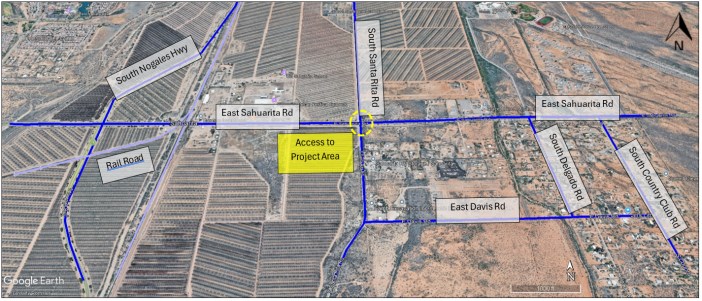
Source: Google Earth, June 2026.
In the Process Plant and surroundings, main access roads referred to the primary site entrance routes and all areas that were required to accommodate heavy-duty traffic, including concentrate trucks and fuel tankers, with a minimum lane of 16 ft and two travel lanes. Internal or secondary access roads supported localized in-plant traffic, typically serving maintenance activities, smaller service vehicles that did not require the capacity of the primary routes and reduced geometric requirements, with a minimum lane of 12 ft and two travel lanes. Service roads consisted of minor routes within independent or isolated areas of the site and were intended for light maintenance access where only small vehicles were required.
|
Road design considers phased construction and operations, dust control requirements, safety and maintainability. Traffic management and access coordination have been identified as key focus areas, particularly during peak construction periods, to avoid conflicts between construction traffic, operational vehicles, and concentrate hauling (see Figure 18-2). Where required, road alignments and standards will be further refined during detailed design to satisfy permit conditions and county requirements.
Figure 18-2: Plant Site Infrastructure - Road Arrangements
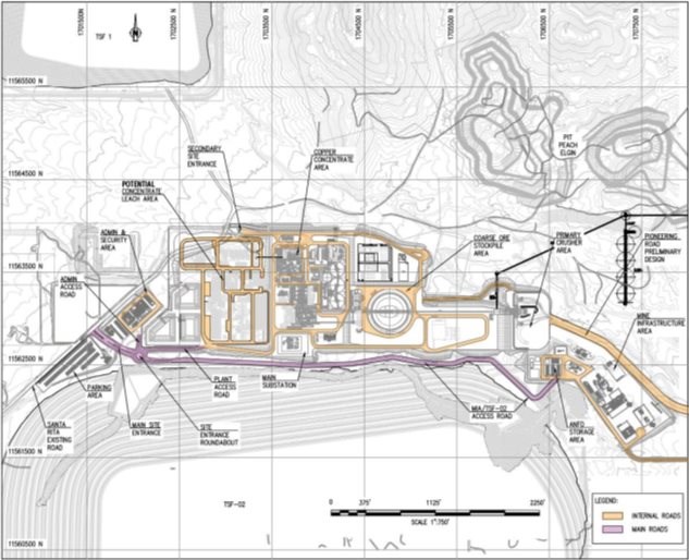
Source: DRA, March 2026.
|
18.2 Processing Plant
The Concentrator Plant has a capacity of 60 kstpd and will process mineralization through conventional crushing, grinding, flotation, molybdenum separation, concentrate dewatering and tailings thickening. The facility also includes a two-stage cyclone station used to produce the sand for dam construction of the TSF.
The Project includes two future development initiatives:
1. In-pit Crushing and Conveying (IPCC) installation
2. Process plant throughput increase from 60k stpd to 90k stpd
The General Plant Site Arrangement is shown in Figure 18-3.
Figure 18-3: General Plant Site Arrangement
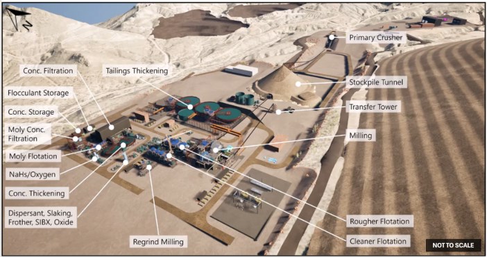
Source, DRA, May 2026.
18.2.1 In-Pit Crushing & Conveying (IPCC) Installation
The In-Pit Crushing & Conveying (IPCC) system has been developed as a strategic materials handling solution to support the planned increase in mining and processing rates while reducing reliance on long-distance truck haulage. The system is designed to provide a continuous, high-capacity ore transport pathway from the East Pit area to the process plant through the integration of primary crushing, conventional overland conveyors, and RopeCon® aerial conveyor technology. The IPCC configuration has been aligned with the life-of-mine plan and developed to minimize surface disturbance, reduce haulage requirements, and maintain operational flexibility.
|
The selected configuration utilizes a hybrid conveying network that combines conventional overland conveyors with aerial conveyor sections to efficiently traverse complex terrain, future mining areas, waste rock storage facilities, and other site constraints. The system has been designed to integrate with future mine development while preserving access to mineral reserves and minimizing interaction with planned infrastructure.
The key IPCC components include:
• Primary Crushing Facility: Installation of a primary gyratory crushing station comprising a truck dump pocket, crusher, discharge systems, rock breaker, dust control systems, and supporting infrastructure. The crushing station provides the initial size reduction stage and establishes the throughput basis for the IPCC system.
• Material Extraction and Feed Regulation: Use of apron feeders beneath the crusher discharge vault to provide controlled and consistent ore flow to the downstream conveying network, protecting conveyor systems from surge loading and ensuring stable operation.
• Hybrid Conveying System: Development of an integrated conveyor network consisting of conventional overland conveyors and two RopeCon® aerial conveyor sections. The aerial conveyor segments span topographic and operational constraints that would otherwise require extensive civil works, additional haulage infrastructure, or significant environmental disturbance.
• Process Plant Ore Delivery: Installation of downstream overland conveyors and plant feed conveyors to transport crushed ore directly to the coarse ore stockpile feed system, providing a continuous and automated feed source to the concentrator.
• Low-Grade Ore Management System: Incorporation of a diverter arrangement, bypass conveyor, transfer conveyor, and tripper conveyor to allow ore routing either to the process plant or to dedicated low-grade stockpiles. This arrangement supports grade control, mine scheduling flexibility, and future processing strategies.
• Power, Controls, and Supporting Infrastructure: Integration of electrical distribution, process control systems, dust suppression, fire protection, communication networks, conveyor stations, transfer towers, and structural support facilities required for reliable long-term operation of the IPCC corridor.
The IPCC strategy replaces a significant portion of conventional truck haulage with continuous conveying, providing operational benefits through reduced haul distances, lower diesel consumption, reduced greenhouse gas emissions, and improved material handling efficiency. By utilizing proven crushing and conveying technologies combined with RopeCon® aerial conveyor systems, the design minimizes technical risk while providing a scalable and constructible solution that can be integrated with future mine expansion plans.
|
Figure 18-4: IPCC Arrangement
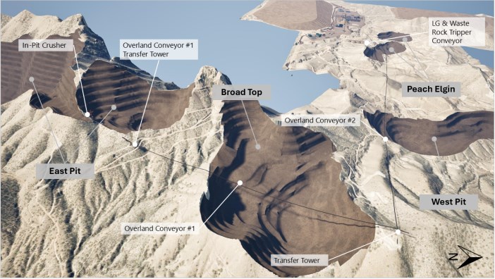
18.2.2 Process Plant Throughput Increase from 60k stpd to 90k stpd
The proposed expansion of the Copper World concentrator from 60k stpd to 90k stpd has been developed as a phased brownfield expansion that builds upon the initial feasibility level development described herein. The expansion strategy is centered on increasing installed processing capacity through the addition of parallel process circuits and targeted debottlenecking of key plant areas while maintaining operational continuity and minimizing disruptions to ongoing production. This approach preserves the established process flowsheet, leverages existing infrastructure, and allows future expansion works to be executed with limited modification to the operating plant.
The expansion has been incorporated into the conceptual plant layout through provisions for additional equipment, utility connections, access routes, and tie-in locations. New facilities are positioned adjacent to existing process areas to maintain operational efficiency, simplify construction staging, and facilitate phased implementation.
The principal process plant modifications include:
• Comminution Circuit Expansion: Installation of a second ball mill and additional pebble crushing capacity to increase grinding throughput and maintain comminution performance at the expanded processing rate. The expansion retains the existing SABC grinding configuration and utilizes parallel equipment to provide additional capacity and operational flexibility.
|
• Flotation and Regrind Expansion: Addition of a third bulk rougher flotation line and a second regrind mill to maintain flotation residence time, froth carrying capacity, and metallurgical performance at higher throughput rates. The expanded flotation arrangement preserves the existing process philosophy while increasing circuit capacity through duplication of proven equipment.
• Concentrate Dewatering Upgrades: Installation of an additional copper concentrate filter and associated ancillary equipment to accommodate increased concentrate production while maintaining dewatering performance and operational redundancy.
• Tailings Management and Dewatering Expansion: Expansion of the tailings thickening and filtration systems through additional thickening capacity and staged tailings filtration facilities to support the increased solids throughput and maintain the filtered tailings management strategy.
• Supporting Infrastructure and Control Systems: Expansion of utilities, materials handling systems, operational technology infrastructure, and selected site facilities to support higher processing rates. The existing process control system architecture is designed to accommodate the additional equipment through integration of new remote I/O, network infrastructure, and supporting control system components.
The expansion philosophy avoids a wholesale replacement or resizing of operating equipment. Instead, capacity is achieved primarily through parallelization and modular additions of proven technologies. This approach significantly mitigates technical and execution risk, simplifies constructability, minimizes operational interruptions during implementation, and provides a practical pathway for staged future development.
Figure 18-5: Throughput Expansion Arrangement
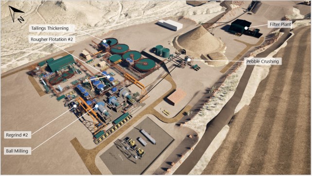
|
18.3 Power Supply & Distribution
Tucson Electric Power (TEP) will provide the electrical power supply for the Project, including the process facilities. TEP will provide service via a 138 kV transmission line connected at the proposed Toro Switchyard which will be located near a private land parcel (Sanrita South), approximately 3 miles (5 km) south of Sahuarita Road and 3.5 miles (5.6 km) east of I-19 near the Country Club Road and Corto Road alignments.
The system will be designed for both the Concentrator Plant base throughput of 60k stpd, an expansion from 60k stpd to 90k stpd, the IPCC System expansion for 90k stpd throughput, and the potential addition of a Concentrate Leach Facility (CLF), as well as potential future tailings expansions for the mine life extension case. Table 18-1 provides a breakdown of installed and operating power per area and includes provisions for the planned expansions.
Table 18-1: Summary of Power Supply by Area
| Phase | Area | Installed (MW) | Demanding (MW) |
| Base Case (60k stpd) | Process Plant | 113.59 | 74.15 |
| Expansion to 90k stpd | Process Plant | 42.04 | 31.74 |
| IPCC Expansion | IPCC | 7.03 | 4.32 |
| CLF Expansion | CLF | 45.64 | 16.31 |
| Tailings Expansion | Tailings Filter Plant | 10.56 | 8.07 |
| Total | 218.86 | 134.59 | |
18.4 Water Supply & Distribution
The primary source of water supply identified for the Project is groundwater in the basin-fill deposits of the upper Santa Cruz Basin, which lies west of the Project and the Santa Rita Mountains. Copper World has a state permit to withdraw groundwater for mineral extraction and metallurgical processing in the amount of 6,000 acre-feet per year which is currently set to expire in January 2028 but renewable for successive terms of 20 years. Water will be provided to a potable water system, freshwater system, process water system, and fire water system.
The mass and water balance for the proposed process flows is based on a design plant throughput of 60k stpd for the sulfide concentrator.
The fresh water and makeup water required for operation of the sulfide concentrator is on average 5,100 acre-feet per year (variable through the years).
The freshwater tank contains a dedicated firewater reserve with a minimum capacity of 186,000 gallons (704 m3). Fire water is pumped from the fresh/fire water storage to fire hydrants, hose reels and fire suppression sprinklers via a dedicated fire water ring main.
Fresh water is transferred to a dedicated gland seal water and distributed where needed. Additionally, fresh water is treated in a water treatment facility to produce potable water for the site buildings, process plant, and mine infrastructure areas. A potable water tank provides storage capacity of 48 hours at average consumption. Potable water is pumped around the site and supplies the plant safety shower system.
|
Process Water stored in the process water tank is for general use and is sourced from tailings thickener overflow and supplemented with plant site run-off collected in stormwater and/or process pond.
Cooling water is used in the SAG mill and ball mill. Chilled water is supplied from a closed-loop chiller system. Water from the cooling water tank is pumped through the chiller to the heat exchangers in the grinding circuits. Warm water is returned to the cooling water tank and recirculated.
Hudbay has made a commitment to recharge 105% of the water it pumps from two primary well fields. Nearly half of the projected Base Case water demand has been acquired and is stored in the Tucson Active Management Area in Marana for this mitigation. Hudbay does not anticipate any significant challenge to satisfying this commitment for the Base Case or Extended Case. This commitment does not impede use of the water subject to the state water right permit.
18.5 Communications
High bandwidth routers and switches will be used to segment the ethernet network and to provide the ability to monitor and control traffic over the network. A voice-over Internet Protocol (VoIP) phone system will be part of the office network, and VoIP handsets will be used for voice communication. Mobile radios will be used by the mine and plant operation personnel for daily control and communications while outside the offices.
The process control system (PCS) is an integrated plant-wide design, enabling the start-up, monitoring and control and shutdown of equipment from the plant control rooms.
The process plant is monitored and controlled from one main control room located in the plant administration and change house building.
A closed-circuit television (CCTV) system is used to assist control room operators in monitoring the operation of the plant and equipment. The CCTV system provides real-time monitoring with archived recording for a nominal period. Camera types include fixed cameras and cameras with remote pan-tilt and/or zoom (PTZ) functions accessible by the control room operators.
18.6 Air Services
Plant air service for use in the process areas will be supplied by two main compressors in the grinding area, and two main compressors in the concentrate handling area. These compressors will provide filtered compressed air to individual plant air receivers in each area where compressed plant air is required.
These four main compressors will also be the source for the instrument air systems. This air will be dried prior to entering the distribution network. Each area will have its own dedicated instrument air receiver to ensure reliable operation of all local area instruments.
|
In addition to these four air compressors, the copper and molybdenum concentrate filters will have their own dedicated air systems which will include compressors and receivers. These air systems will be sized to accommodate only the needs of these specific pieces of equipment.
18.7 Tailings Storage Facility
The Base Case includes the construction of three Tailings Storage Facilities: TSF-1, TSF-2, and the southern portion of TSF-N. Tailings deposition will include both conventional (i.e., hydraulic) deposition and filtered tailings stacking (Figure 18-6).
Figure 18-6: Infrastructure Arrangements
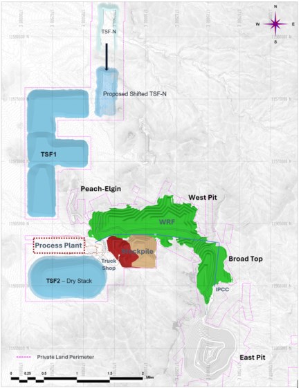
|
18.7.1 Tailings Storage Facility Designs
The Tailings Storage Facilities (TSFs) have been designed to receive tailings from the processing plant at a nominal rate of 60 kstpd from Year 1 through Year 4 and 90 kstpd from Year 5 onward. The tailings generated from the 30,000 stpd expansion in Year 5 will be filtered and stacked, while the remaining 60 kstpd will be cyclone-separated and deposited hydraulically. The design criteria and objectives include:
• Provisions storage of a minimum of 435 million tons, including TSF-1 (235 million tons), TSF-2 (162 million tons), and the southern portion of TSF-N (38 million tons), which is sufficient for the material to be mined during the 15 years of processing life for the base case
• Designs in accordance with the requirements of the Arizona Department of Environmental Quality (ADEQ) and Arizona Mining Best Available Demonstrated Control Technology ("BADCT") Guidance Manual, and accordance with TSM Tailings Standard.
• Site-specific design criteria and design bases based on hydrological and geotechnical studies that included regional climate data, drilling and testing programs, and laboratory characterization of subsurface and tailings samples.
• Establishment of an effective and efficient reclamation program.
The tailings facility in the southern portion of TSF-N is considered a tailings facility in the mine plan described in this Technical Report and supporting financial models. However, its location considered optional at this time and noted as such on Figure 18-6. In the current mine plan, this location would not be utilized for tailings storage until Year 11 of operations. Hudbay has recently acquired land south of TSF-N and intends to conduct a design update to utilize this land, as shown in the proposed shifted TSF-N (Figure 18-6).
The tailings facilities will consist of multiple cells. For each cell, a TSF starter dam (start phase) will first be constructed using locally borrowed soil and waste rock; the main starter dam along the downgradient edge of each cell will be raised by centerline construction methods.
The subgrade areas of the TSF starter dam embankments, and the area of impoundment for the discharge control treatment, will be stripped of existing vegetation, debris, and other deleterious materials. Areas designated to receive embankment fill will be further prepared by the removal of any loose alluvial or colluvial soils. Benches will be wide enough to accommodate compaction and earth moving equipment, and to allow the placement of horizontal lifts of fill.
18.7.2 Stability Analysis
Geotechnical site investigations and laboratory testing were completed by WSP as prior to commencing Feasibility Study level design by Knight Piésold. Recent site investigation work was supplemented with historical data to form the basis of the design. In addition to the field and laboratory investigation, samples of potential borrow materials were collected and tested from within the Project area for the construction of the TSFs. Knight Piésold conducted additional laboratory testing to address data gaps associated with TSF foundation strength and waste rock material strength.
|
The slope stability analyses performed by Knight Piésold to assess the slope stability of the TSFs designed to support the Project included both static (drained and undrained), pseudo-static, and post-earthquake analyses were performed using the SLOPE/W Version 11.3 (Geo-Slope, 2021) computer program to perform limit equilibrium slope stability tests using the Spencer's method of slices (Spencer, 1967).
Site characteristics were assessed during geotechnical investigations in 2021, 2022, and 2025 using test pits, drill holes, and laboratory and in-situ testing completed by WSP. A total of 34 borings and 117 test pits were performed within the footprints of TSF-1 and TSF-2. In 2022, an additional 9 test pits were performed in the footprint of TSF-N.
Critical cross sections were selected to evaluate the stability of TSF-1, TSF-2, and TSF-N. The selected sections are along the maximum heights and representative configurations of the tailings dams at different cells in different locations. Stability analyses were performed for these sections to evaluate the slope stability of the TSFs during and after construction. The stability analyses included construction stage analyses with both static and pseudo-static analyses performed.
The foundation material consists, in general, of alluvium (including GP, SP, and SW soil types), highly to completely weathered rock, and moderately to slightly weathered rock. All factors of safety meet or exceed the minimum design criteria for static and pseudo-static loading conditions per ADEQ - BADCT guidance manual.
To support stability analyses, steady-state seepage analyses of the critical sections were completed to assess the water and pore-water pressure conditions during the construction of the tailings dam and to evaluate dam stability at a maximum pool condition. In general, the seepage analyses indicate low pore pressures within the embankment slopes and the phreatic surface drops vertically across the relatively high permeability coarse tailings embankment. This drainage is further aided by the relatively high permeability of the Alluvium underlying the embankments.
18.8 Waste Rock Facility
The Waste Rock Facility (WRF) will receive waste rock from all the pits, starting from the west side area. The WRF will be large enough to contain the estimated 589 million tons of waste rock generated from within the proposed limits of the pits for the base case (Figure 18-6).
The WRF will be constructed with maximum lifts of 100 ft, stacked at the angle of repose, with benching and inter-lift slopes of approximately 1.3H:1V to give the facility an overall slope of 2.2H:1V. The original ground consists of layers of alluvium or colluvial soils overlying weathered rock; the contact between soil and rock in the WRF area is approximately 30 ft deep. The alluvium and weathered rock will be removed in much of the WRF's footprint prior to waste rock placement as part of pit development, although it will be left in place in some areas. These materials are dense and dry enough that the possibility of liquefaction of the foundation or waste rock is very low given the tectonic environment of the Project area. The design of the WRF considered field and laboratory testing data collected on both the foundation material and the waste rock. Both materials were recently tested in Knight Piésold's laboratory (Knight Piésold 2026a, 2026b), and it is anticipated that additional investigation and testing will occur during the detailed design phase.
Limit equilibrium slope stability analyses were completed on the Year 1 and Year 15 configurations of the WRF and considered critical cross-sections around the facility where slopes are steepest, loading is highest, and/or project infrastructure is nearby. Per the results of laboratory testing and anticipated operations conditions, drained, dilative behavior is expected from the foundation soil and waste rock; therefore, only the static drained and pseudo-static loading conditions were evaluated. Buildup of a phreatic surface within the waste rock pile is not expected due to its large particle size and surface water management structures included in the design. In the stability analyses, only a phreatic surface representing the local groundwater level was included in the models. Rock-like materials were modeled as impenetrable such that block-type slip surfaces along the waste rock/rock interface could manifest, and Spencer's Method of slices was used to calculate the corresponding factor of safety (FoS). Slope stability acceptance criteria, represented by the minimum required FoS, for the different loading conditions were established with consideration to both local BADCT and international standard. The results of the analyses indicate the WRF as currently designed met the required minimum FoS for each configuration, cross section, and loading condition analyzed.
|
18.9 Site Water Management
The site water management strategy has been developed within the bounds of the approved permits and considers the protection of the groundwater and recognizes surface water resources.
18.9.1 Stormwater Management Facilities
The stormwater management facilities will divert clean runoff (i.e., non-contact water) from the Project site, to minimize the amount of water that must be managed or treated, via a system of designed diversion channels and collection galleries. The construction of these surface water control structures will start during the initial construction of the Project. Diversion channels and galleries will convey water either to a natural drainage or to a stormwater collection gallery in alignment with issued permits.
Contact water will be managed with channels, sumps, and ponds and be used in the process water circuit. These elements are designed as per the issued permits.
Three stormwater ponds are proposed (HLF North Stormwater Pond, HLF South Stormwater Pond, and Process Area Stormwater Pond). The three stormwater ponds will be single lined since these will primarily be for startup water, stormwater and/or contain process solutions for a short period of time during upset conditions.
18.9.2 Tailings Storage Water Management
Tailings stormwater management will be required prior to the start of the tailings deposition and will include stormwater collection sumps and stormwater diversions. The contact stormwater and seepage from the TSFs are mixed in the stormwater collection sumps and non-contact water is managed as stated in the previous section.
Seepage from TSFs will be collected in an underdrain collection system that will report flow to several seepage collection trenches located at the downgradient toe of the TSFs. Solution and contact water captured in the seepage collection trenches and sumps will be pumped to the supernatant pond and then the Primary Settling Pond and recycled into the process water circuit.
|
18.9.3 Waste Rock Water Management
The waste rock material has been identified predominantly as non-acid generating (NAG) material and therefore does not pose a significant threat for the formation of acid mine drainage. During operations, waste rock material will be used to backfill three other pits: Peach-Elgin, West, and Broadtop Butte. The waste rock facilities will be constructed with a slight grade to promote runoff from the top and benches, and the compacted surface will also promote runoff. Runoff will be conveyed by benches to a low point in the natural topography, where stormwater runoff will be collected in a WRF sediment basin and discharged to the natural drainage as non-contact water. A small amount of runoff will flow into the pits to be recovered into the existing pits water management system.
18.10 Mine & Other Infrastructure
Site buildings and ancillary facilities include administrative offices, control rooms, maintenance facilities, warehouses, laboratories, medical facilities, security buildings, and change houses. The location and layout of buildings consider security, access control, operational efficiency, and separation from hazardous areas. Centralized facilities are favored to improve communications, minimize duplication, and simplify utilities distribution. Figure 18-7 presents the general arrangement of the site buildings and ancillary facilities.
Figure 18-7: General Arrangement of Potential Concentrate Leach Facility and Ancillary Facilities
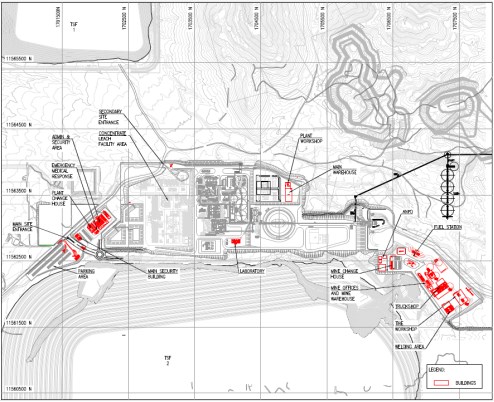
Source: DRA, March 2026.
|
18.10.1 Mine Infrastructure
The mine buildings and support facilities are located to the east of the process plant area off the main haul road and include the following:
• Truck Shop: heavy-equipment facility sized to accommodate haul trucks and loaders. Incorporated three full-size maintenance bays for large mining equipment, along with one additional bay for smaller units such as graders, dozers, and drills. The design included a dedicated lubrication bay and storage area, and the western portion of the site was reserved to support future expansion
• Welding Shop: dedicated to the fabrication and repair of truck trays, shovels, and other heavy equipment. Positioned within the Mine Infrastructure Area but isolated from the main truck shop to control exposure to welding fumes, noise, light flashes, and sparks.
• Tire Workshop: developed as a non-enclosed concrete pad, and roofed structure. Incorporated level concrete slabs sized to support operation of the truck and tire-changing machine. Will allow a tire handler, such as a Caterpillar 988, to position all four wheels on the pad to maintain stability while maneuvering.
• Truck Wash: designed with a single wash bay, oil separator, and a water recycling system, compliant with environmental and operational requirements and positioned in the Mine Infrastructure Area.
• Mine Offices and Mine Warehouse: developed as a two-story building, integrating administrative, operational, and warehousing functions.
• The first floor includes the mine warehouse, tool storage, shift-start room, electrical workshop, and specialized tool room; while the second floor consists of offices and meeting spaces.
• Mine Change Rooms: Including parking provisions for light and service vehicles, configured to support efficient personnel flow during shift change operations.
• Explosive Magazine Area: will consist of an enclosed building constructed on concrete pads or self-container units specifically designed for explosives storage.
• Heavy Equipment Fuel Storage and Dispensing: will consist of storage tanks and associated pipelines, located within a concrete secondary containment structure.
• Light Vehicle Fuel Station: will consist of storage tanks and associated pipelines within a concrete secondary containment structure.
18.10.2 Plant Maintenance Shop, Warehouse, & Plant Administration
The plant maintenance shop, warehouse, and plant administration building will be located on the plant site. The plant maintenance workshop area and warehouse constitute one building located to the north of the crushed feed stockpile and east of the concentrate handling area. Access to this facility will be from the main site access road.
The plant administration building will be located just to the east of the plant site entrance and guard house. This building will contain administration offices and facilities, change houses, and the control room. This will also be the location of the primary parking lot for site operations staff and visitors, with an overflow lot to be located on the west side of Santa Rita Road adjacent to the guard house.
|
Key buildings comprise:
• Laboratory: including a sample preparation room, metallurgical testing laboratory, assay laboratory, and dedicated space for concentrate-leaching sample activities, as well as offices and auxiliary rooms.
• Main Warehouse: located at the Process Plant Terrace, designed to accommodate heavy-duty racking systems, forklift circulation, and standard inventory management operations.
• Plant Workshop: including a repair bay for plant mobile equipment, maintenance offices, and an electrical shop. Located at the Process Plant Terrace.
• Administration Building and Control Room: designed as a two-story building located within the Administrative Area. Planned to accommodate private offices and cubicles. The first floor includes offices, meeting rooms, break areas, and meeting and training spaces, while the second floor primarily accommodates additional offices and an Integrated Control Room.
• Plant Change House: This facility includes restrooms, showers, uniform storage areas, and clean supply storage. It provides direct access to the Line Out room and to the exterior of the building to support efficient personnel circulation.
• Emergency Response Facility: designed to include two rooms, a storage area, and a reception space. It supports emergency care, new-hire medical evaluations, fit testing, and occupational health management.
• Main Security Building and Gatehouses: The first security building is located at the site entrance, and it's designed to serve as the primary checkpoint for visitors and personnel, providing secure access control and check-in functions. A secondary gatehouse will be located on the north side of the Process Plant at its intersection with Santa Rita Road. This gatehouse will function as the controlled truck entrance for heavy-vehicle traffic, including concentrate trucks. The Main Security Building was designed to accommodate a training room, a lunchroom/line out room, and a visitor reception area.
• Parking Areas: designed to provide approximately 350 off-site spaces and approximately 100 on-site spaces, with layouts that allow large truck turnaround, visitor parking, and capacity for day-shift peak plus contractors.
• Truck Scale: located within the concentrate loadout area.
 |
19 MARKETING
19.1 Copper Concentrate
For the financial model supporting the Base Case and the mineral reserve estimates, the copper produced at Copper World will be in the form of concentrate and will be sold externally. The concentrate quality is expected to be clean and highly marketable. Pursuant to the terms of the Joint Venture Agreement, Hudbay is entitled to 70% of the copper concentrate production from the Project and Mitsubishi is entitled to the remaining 30%. Each partner will enter into an offtake agreement with Copper World LLC to purchase its pro rata share of the concentrates on the same, industry standard, terms. Each partner will then be free to market and re-sell its share of the concentrate production to the global market.
If the option of adding a concentrate leach facility is pursued and copper cathodes are produced, copper concentrate would be sold externally, but in lesser volumes due to copper cathode being produced as well. Any copper cathode production would be subject to the same pro rata marketing arrangement with the joint venture partners.
Global copper concentrate market fundamentals are expected be supportive. Mine production globally is expected to continue to struggle to meet metal demand, in spite of compelling economic incentives. In parallel, global smelting capacity will continue to grow, as many countries seek to add capacity in an attempt to control critical mineral supply chains. Consequently, there is expected to be strong demand for Copper World concentrate, which is reinforced by preliminary discussions undertaken with various industry participants to date.
This imbalance between supply and demand for copper concentrate will be reflected in treatment/refining charges, as well as other commercial terms, which are expected to be more favourable than historical.
19.2 Molybdenum
Copper World will produce a molybdenum concentrate for external sale. As with the copper concentrates, pursuant to the Joint Venture Agreement, Hudbay is entitled to 70% of the molybdenum concentrate production from the Project and Mitsubishi is entitled to the remaining 30%. Each partner will enter into an offtake agreement with Copper World LLC to purchase its pro rata share of the concentrates on the same, industry standard, terms.
Market fundamentals are expected to be supported by strong specialty steel demand.
Copper World molybdenum is expected to be roasted in the US.
|
Figure 19-1: Global Copper Production and Primary Demand
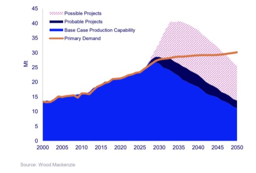
19.3 Marketing Related Logistics
Based on current smelting capacity in the United States / North America, the majority of the copper concentrate sales are expected to be shipped to Asia, shipped through the port of Guaymas, Mexico. Enclosed containers will be carried by truck, in what is a well-established logistical solution in that region. A lesser proportion of the total volume may be sold regionally by rail, providing a degree of diversification to the logistics strategy.
19.4 Marketing Assumptions Used in the Economic Model
Table 19-1 summarizes the assumptions used for the relevant commodities to be sold and purchased, and Table 19-2 summarizes the other relevant marketing assumptions used in the economic evaluation of the Project.
Table 19-1: Price Deck Summary
| Metric | Unit | Long-Term Price |
| Metals | ||
| Copper1 | $/lb | 5.00 |
| Molybdenum1 | $/lb | 17.50 |
| Gold - Offtaker1 | $/oz | 3,600.00 |
| Silver - Offtaker1 | $/oz | 45.00 |
| Gold - Stream (15% of market price)2 | $/oz | 540.00 |
|
| Metric | Unit | Long-Term Price |
| Silver - Stream (15% of market price)2 | $/oz | 6.75 |
| NSR Royalty | % | 3.00 |
Notes: 1. Commodity price assumptions in the table represent long-term prices starting in Year 3 of operations. Price assumptions in Year 1 and Year 2 of operations are as follows: copper $5.50/lb and $5.13/lb, gold $3,788/oz and $3,638/oz, silver $46.25/oz and $45/oz, molybdenum $17.50/lb in both years. 2. Gold and silver stream based on 15% of the market price as stipulated in the stream agreement with Wheaton, estimated at $540/oz for gold based on $3,600/oz gold price assumption and $6.75/oz silver based on $45/oz silver price assumption.
Table 19-2: Other Marketing Assumptions
| Price / Rate | Unit | Long Term |
| Copper Concentrate - Sales | ||
| Treatment Charge1 | $/DMT | 55.00 |
| Refining Charge - Cu1 | $/lb. | 0.055 |
| Payable % - Cu1 | % | 96.50 |
| Minimum deduction - Cu2 | % | 1.00 |
| Freight | $/WMT | 161.00 |
| Moisture | % | 10.00 |
Notes: 1. Treatment charge is $45/dmt for Years 1 to 7, and $55/dmt long-term. Refining charge is $0.045/lb for Years 1 to 7, and $0.055/lb long-term. 2. 92.5% of the gold and silver contained in the mineral products produced from the Project (other than any gold production that is less than 1g/t in concentrate during the first four years of operation), is subject to the Wheaton stream agreement as disclosed in this Technical Report. Assumptions for payable percentages, minimum grades for payment and refining charges for silver and gold in the copper concentrate sold to off takers are generally consistent with industry standards, taken as a whole.
The Qualified Person has reviewed the marketing assumptions used in the financial evaluation of the Project and has validated their supporting documentation and logic.
|
20 ENVIRONMENTAL STUDIES, PERMITTING, & SOCIAL OR COMMUNITY IMPACT
This section provides a summary of the following environmental-related efforts in support of the Project:
• Environmental studies and baseline site assessments.
• Permitting requirements, existing and planned permitting.
• Social or community related requirements and plans.
• Description of management plans for waste rock, tailings storage, open pit areas, process plant, site monitoring and water management.
• Mine closure (remediation and reclamation) requirements and estimated costs.
Permits issued for the Project include specific design, operating and monitoring requirements. For example, the Project will meet the Arizona Department of Environmental Quality (ADEQ) Best Available Demonstrated Control Technology (BADCT) requirements for designated Project components under the Aquifer Protection Permit (APP) (including the Waste Rock Facility and Tailings Storage Facility design). Operating capacities, equipment specifications and efficiency standards are included in the permit requirements for the Class II Air Quality Permit issued by ADEQ. Monitoring and reporting requirements are outlined in the permits associated with the Project.
20.1 Environmental Studies
As the Project has advanced in development and design, surveys and studies were conducted to define the biological, cultural, groundwater and surface water hydrology, geochemical characterization and other environmental/social constraints of the Project. These surveys and studies were performed to characterize and assess potential impacts to the environment by the Project are summarized below.
20.1.1 Biological
Biological surveys have been conducted on Hudbay's private land holdings and portions of the surrounding areas. These surveys included federally listed special status plant and animal species. Hudbay has developed a Special-Status Species Management Plan for the Project to mitigate risk of impacts to these species. This management plan includes best management practices (BMPs) to avoid "take" of listed species while conducting ground-disturbing activities on private lands. Biological survey work has resulted in the identification and management planning for special-status plant and animal species and the development of awareness and avoidance training for site personnel.
20.1.2 Cultural
Cultural resource surveys have been conducted on Hudbay's private land holdings and portions of the surrounding areas. Historic and pre-historic sites that are eligible for inclusion in the National Register of Historic Places have been identified. Data recovery at these sites is conducted in accordance with site management plans prior to initiating ground-disturbing activities.
|
Data recovery on most of the eligible historic sites within Hudbay's private lands has been completed. Additionally, data recovery for pre-historic sites is currently underway, mostly completed, and performed in accordance with the site's Archeological Data Recovery Work Plan for Pre-Historic Sites. These sites are located both on private land and within Hudbay's right-of-way (ROW) on State land associated with the Utility Corridor. The data recovery work plan was provided to several tribes for input prior to implementation. This included the Tohono O'odham Nation. The Tohono O'odham Nation, which also routinely participates in data recovery efforts on these pre-historic sites. Several other tribal partners regularly attend field work update meetings on the data recovery efforts.
Site development activities are conducted in accordance with Hudbay's internal cultural resource protocols. These protocols describe how Hudbay addresses cultural resources, including the potential discovery of human remains or funerary objects. Human ancestral remains discovered on lands associated with the Project are treated with dignity and respect.
20.1.3 Geochemical
Geochemical characterization of the materials to be mined and placed in storage facilities has been undertaken as part of the facility design process for both the East side and West side mine areas. A waste rock management plan was developed as part of the characterization program to mitigate against the occurrence of acid mine drainage from potentially acid-generating (PAG) or acid-generating (AG) materials. Overall, most waste rock is constituted of limestones and has been identified as non-acid generating (NAG). Therefore, the risk of forming acid rock drainage is low based on characterization of the waste rock and Hudbay's material management plan.
20.1.4 Groundwater
Overall, the groundwater system in the main Project area is limited and discontinuous. There is minimal storage due to the low porosity ranges of the geologic units and no significant groundwater flow or movement over significant distances due to the lack of established interconnected fracture networks. The complex geologic framework and geometry of contacts, fault traces and intrusive features create significant additional discontinuity in the bedrock system which further limits groundwater movement. Many studies have been conducted in the Project vicinity to characterize geology, mineral resources and hydrogeology, including exploration drilling, field investigations and modeling studies. Pumping wells in the Project area produce very low quantities of water, owing to the low permeability of water-bearing rocks and disconnected and compartmentalized nature of the groundwater system.
Groundwater flow modeling has been developed in support of Project permitting efforts, impact assessment and design development. The modeling approach was largely based on combining aspects of previously developed models for the East and West sides into a single Project model. The modeling study provides groundwater drawdown predictions from dewatering and defines the Discharge Impact Area (DIA) of mine facilities permitted under the APP Program. Routine groundwater monitoring is required during operations and post-closure at the designated point-of-compliance (POC) monitoring locations.
|
20.1.5 Surface Water
The Project is in an arid region typical of the United States (US) desert southwest. The surrounding terrain is mountainous and rugged, with elevations ranging from 3,800 to 6,300 feet above mean sea level (amsl). The main contributing drainages in the Project area on the west side of the Santa Rita Mountains generally drain to the north and west, while the drainages on the east side of the Santa Rita Mountains flow to the north and east. A network of small arroyos on the west side flows to the alluvial fan, with most ending in the alluvial fan or forming larger unnamed channels that traditionally flowed to the Santa Cruz River, the main downstream tributary on the west side.
Drainages on the east side of the Santa Rita Mountains generally flow northeast. The East Pit is near the ridge separating the east and west side of the Santa Rita Mountains. The East Pit is within the Davidson Canyon watershed near the top of the Barrel Canyon Wash. The Barrel Canyon Wash confluences with the Davidson Canyon Wash which then confluences with Cienega Creek to the north and west of the Project site.
Surface water resources at the site will be managed in accordance with a Site Water Management Plan (SWMP) developed for the Copper World Project to ensure compliance with regulatory requirements. Components of the SWMP include assuring the integrity of mine facilities and the minimization of on-site and off-site storm-generated erosional effects. Specific objectives include:
• To the extent practicable, diversion of unimpacted (non-contact) stormwater to downgradient drainages.
• On-site containment of process water (contact water).
• Design and implementation of effective permanent, long-term engineered controls as well as temporary, short-term controls for construction.
• Minimization of erosional effects on-site and off-site.
• Assure the integrity of mine facilities during active mining, closure, and post-closure.
• Routing of stormwater off and through reclaimed facilities at closure as much as practicable.
• Non-degradation of surface water quality downgradient of the facilities and operations.
20.1.6 Traffic
A Traffic Impact Assessment (TIA) was conducted to evaluate the potential traffic impacts associated with mine construction (2027-2028) and mine operations (beginning 2029), to identify whether roadway or intersection improvements may be implemented as mitigation. Historic traffic volume data was used to establish a 4% annual background growth rate for this study.
20.2 Project Permitting
All the state, county, and local permits and/or authorizations required to start the Projects have all been issued. Some of the major permits will require an amendment after the Project comes into operation (i.e., for the mill expansion and IPCC system) or renewal in the normal course.
|
Table 20-1 summarizes these major permits, associated agency, and permit status. The table also indicates the permit expiration and/or term limits.
Table 20-1: Project Permitting Status
| Permit | Agency Type | Agency/Description | Status | Term |
| Groundwater Withdrawal Permit No. 59-215979.0001 | State | Arizona Department of Water Resources (ADWR) - mineral extraction permit (MEP), maximum 6,000 acre-feet per annum | Issued: Jan 18, 2008 Amendment: Oct 25, 2024 |
20 yrs - Jan 17, 2028 (Renew as needed) |
| Arizona Mined Land Reclamation Plan (MLRP) | State | Arizona State Mine Inspector (ASMI) - bonding for reclamation of disturbances/facilities under approved MLRP | Issued: May 5, 2022 | Life of Facility (Amend as needed) |
| Class II Air Quality Permit No. 96659 | State | Arizona Department of Environmental Quality (ADEQ) - for construction and operation | Issued: Jan 2, 2025 | 5 yrs - Jan 1, 2030 (Amend as needed) |
| Air Quality Dust Activity Permit | State | ADEQ - pre-construction activities | Issued: May 4, 2026 | 1 yr - May 3, 2027 |
| Aquifer Protection Permit (APP) No. P-513690 | State | ADEQ - groundwater discharge permit, authorization to operate | Issued: Aug 29, 2024 | Life of Facility (Amend as needed) |
| Certificate of Environmental Compatibility (CEC) | State | Arizona Corporation Commission (ACC) & the Line Siting Committee - for construction of power line (issued to Tucson Electric Power Company [TEP]) | Issued: Jun 12, 2012 Extensions - Sept 20, 2018 & Jun 29, 2022 |
7 yrs - June 2029 |
| Floodplain Use Permits | County | Pima County Flood Control District - multiple permits for water line construction, diversion channels | Various | Annual renewals until constructed |
| Right of Ways | State | Arizona State Land Department (ASLD) - multiple ROW permits for utility corridor | Issued: Mar 7, 2017 | 50 yrs - Mar 6, 2067 |
| Right of Way | State | Arizona State Land Department (ASLD) - ROW permit for access road and utilities | Issued Dec 9, 2022 | 30 yrs - Dec 8, 2052 |
| Right of Way Encroachment - License Agreement | Local Town/City |
Town of Sahuarita (TOS) - license agreement to construct water pipeline within town ROW | Issued: Jun 24, 2013 | 25 yrs - Jun 23, 2038 |
The following permit is issued and will be modified as needed during construction or pre-construction activities:
• Fugitive dust permit (Pima County)
20.3 Social and Community Requirements & Plans
Hudbay is committed to ensuring that the local community benefits from the Project. This begins by soliciting input from stakeholders and understanding the challenges facing the local communities. The information acquired can then be used during the development process to protect critical resources and effectively mitigate impacts that cannot be avoided.
|
Several of the permits described above included opportunities for public comment where interested stakeholders were encouraged to share their views on the Project. In addition, Hudbay intends to engage key stakeholders on an ongoing basis to directly solicit their input. This information will be used to develop effective mitigation strategies as the Project progresses and the community is engaged. A mitigation cost allowance is included in the financial model for the Project.
For example, Hudbay has been actively engaged in the preservation of historic and pre-historic resources and has developed a data recovery protocol for cultural resources. As part of this protocol, field surveys are conducted prior to any site disturbance. Data recovery plans are also developed for eligible sites to archive site artifacts and history. Hudbay is also actively engaged in reaching out to tribal entities that may have cultural ties to the land.
Another example is Project Renews, which is a Joint Venture between Community Water of Green Valley (CVC) and Copper World. Project Renews is fully funded by Hudbay and involves construction of infrastructure to transport Central Arizona Project water from the CAP terminus to a recharge area to benefit the aquifer and the local community. This will allow both entities to receive their CAP allocations. Copper Water will use its CAP allocation to voluntarily mitigate its pumping with out of basin water.
20.4 Details and Monitoring
This section provides a summary of water management associated with the major facilities, including facility design components and overall Project monitoring requirements.
20.4.1 Waste Rock Facility
Preliminary design of the Waste Rock Facility (WRF) has been completed approved as part of the in preparation of an Aquifer Protection Permit granted by application to ADEQ. Additionally, geotechnical investigations and stability analyses were completed. The design incorporates temporary sediment basins to be used until the final configuration of the WRF is completed. Once each section of the WRF is finalized, permanent sediment basins will be constructed. Final WRF slopes will be seeded at closure. As much as practicable, stormwater runoff from the WRF will be released offsite through sediment basins.
A waste rock management plan has been developed to mitigate the potential for acid generation in the waste rock material. NAG materials will be preferentially placed on the outer slopes to ensure surface water meets the required standards. The waste rock management plan was part of the Aquifer Protection Permit (APP) application for the Project.
20.4.2 Tailings Storage Facility
Geotechnical investigations, stability analyses, and laboratory testing for the Tailings Storage Facilities (TSFs) were completed as part of the design process and were supplemented with historical data to form the basis of design. The design is in accordance with ADEQ's Arizona Mining Best Available Demonstrated Control Technology (BADCT) Guidance Manual.
|
The TSFs will all have a conventional impoundment design. Water management for the TSFs includes the capture of drain-down solution (seepage) in an underdrain collection system for reuse in the process. Impacted stormwater is also captured and pumped to the process circuit. Unimpacted stormwater is released to downgradient drainages.
The seepage collection system for the TSFs will be operated throughout the life of the facility and into closure. In addition to managing seepage at closure, stormwater will be managed. A growth media cover will be placed on the surface and side slopes of the TSFs and revegetated. The top surface will be graded as needed to route stormwater off the facility and into natural drainages. This will limit the potential for infiltration of precipitation events into the tailings. The use of sulfate treatment cells is also anticipated in the post-closure period.
20.4.3 Open Pits
The Project will involve mining four open pits. These pits, from west to east, include Peach-Elgin, West, Broadtop Butte, and East pits. Current plans outline the backfilling of the West and Broadtop Butte pits, as well as the Peach-Elgin pit. The East Pit currently is expected to remain open at closure, although this will be further evaluated.
Dewatering will be conducted as needed during operations for the open pit areas. Water from dewatering wells will generally be used in processing or for general dust control. Stormwater collected in pit sumps will be used for dust control within the pit shells or be pumped to the processing circuit.
Site investigations and pit slope stability analyses were conducted to demonstrate adherence to recommended slope safety factors.
20.4.4 Process Plant
The Plant site area will contain four lined ponds, three of which are considered process ponds: Primary Settling Pond, Reclaim Pond, and Raffinate Pond. The fourth pond (Process Area Stormwater Pond) is a stormwater pond that will receive runoff from the Plant site area during storm events.
The Plant Site pond designs include the following BADCT components:
• A double-lined composite liner system for the process solution ponds with a leak collection and removal system (LCRS)
• A single-lined composite liner system for the stormwater pond.
The remaining Plant site's operational and maintenance facilities will be designed and constructed as a non-discharge facility to meet exemptions listed in Arizona Revised Statute (A.R.S.) §49-250(B).
Facilities will be removed at closure, including the plant area ponds.
20.4.5 Monitoring and Inspections
The following monitoring and inspections will be performed during operations:
|
• Fugitive dust and stack emissions monitoring
• PM station monitoring (dust particulates)
• Meteorological station monitoring (wind speed, rain fall, etc.)
• Air pollution control equipment testing
• Stormwater sampling at outfalls
• Groundwater level and water quality monitoring (at POC or other monitoring wells)
• Waste rock testing and monitoring of material placement
• Inspection of pond liner integrity and general pond function
• Monitoring of pond leak collection and recovery system (LCRS) where applicable
• Inspections of waste rock and tailings slope stability
• Pit slope stability/ground control monitoring
• Inspection of conveyance channels
• Moisture content of tailings
• Fresh water pumping volume
20.5 Social and Environmental Benefits of the Project
The company is evaluating several GHG emission reduction strategies for Scope 1 and 2 emissions, including:
• Alternative fuels: moving from diesel to transition fuels like biodiesel for trucks, excavators, and drills, as well as shifting to green hydrogen for haulage trucks.
• Construction of an IPCC system to reduce haulage truck emissions.
• Decarbonized electricity through renewable power purchase agreements.
• Installation of wind and/or solar farms at the Copper World site.
• Reductions in general carbon sourced power mix at the power provider. Tucson Electric Power (TEP), the local distributor of power to Copper World, has a published plan to provide more than 70% of its power from wind and solar resources as part of a cleaner energy portfolio. This is estimated to reduce TEP's carbon emissions by 80% by 2035.
Additionally, if Hudbay intends to adopt a filtered tailings system as part of the Extension Case, this reduces the overall water consumption required by the process.
|
The net economic impact of the Project is estimated at $1,126M for the Base Case, considering only total U.S. taxes over the life of mine, including $200M to the State of Arizona and $362M in local property taxes. It is anticipated to generate over 750 construction jobs, 500 permanent operating roles, and up to 3,000 indirect employment opportunities within Arizona.
20.6 Reclamation and Closure
Copper World assumes responsibility for reclamation of surface disturbances that are attributed to the Project. Reclamation and closure on non-federal lands is regulated by ADEQ and ASMI. Reclamation of surface facilities is covered under a Mined Plan Reclamation Plan (MLRP) approved by ASMI. The closure of discharging facilities is described in a Conceptual Closure Plan approved by ADEQ as part of the area-wide APP. The current MLRP and area-wide APP will be amended, including any as-needed updates to the closure and reclamation costs. Closure and reclamation bonding will be apportioned amongst the agencies as applicable.
20.6.1 Reclamation and Closure Concepts
In general, the following concepts apply to reclamation and closure of the facilities:
• Post-mining land use to include ongoing ranching and wildlife habitats. The top surfaces of the post-mining reclaimed facilities will be used for grazing once vegetation is established.
• Placement of materials in their final configuration throughout the life of the Project, where possible. Facility slopes will be constructed at final reclamation slopes. Final reclaimed facility surfaces will consist of either suitable waste rock or salvaged soil materials.
• Facility grading and stormwater controls will be designed to route as much stormwater runoff from the reclaimed surfaces to downgradient drainages as practicable.
• Building facilities within the Plant site will be removed and the area regraded to route stormwater runoff to downgradient drainages. Reclaimed areas will be covered with growth media as needed (i.e., soil salvaged from the facility footprints) and revegetated.
• Reclamation of the Utility Corridor includes the removal of facilities (such as the water and power lines and pump stations) and the regrading and revegetation of disturbed areas.
• Perimeter fencing will remain, especially around pit areas. Some of the pits will also be backfilled.
Additionally, the following post-closure site monitoring and activities are anticipated:
• Management of drain-down solutions from the tailings facilities (active management followed by passive management)
• Groundwater monitoring at point of compliance (POC) wells
• Surface water monitoring at outfall locations
|
• Reclamation success monitoring and maintenance, including stormwater conveyance monitoring and maintenance (includes erosion monitoring and maintenance)
Drain-down solution management will be variable for the facilities and could be up to 30-years for the TSFs. Reclamation success monitoring and maintenance is anticipated to occur for 5-years once final covers and/or reclamation activities occur. Reclamation will be staged as needed. Concurrent reclamation will be employed where practicable.
20.6.2 Base Case Closure Costs
For the purposes of this Definitive Feasibility Study, the estimated closure and reclamation costs attributable to ADEQ and to ASMI are approximately $101.0M and $36.7M, respectively.
20.6.3 Financial Assurance
Certain permits require financial assurance to ensure the success of mitigation, while others are solely to ensure that adequate funds are available at closure. The requisite bonds for the Project are expected to be obtained from the surety market with an estimated annual bond fee of 1.00% of the bond's notional value.
Bonds will be required for ADEQ (closure of discharging facilities) and for ASMI (reclamation of disturbances, including the removal of facilities). Bonding will cover about $101.0M for APP-related closure costs and about $36.7M for ASMI-related reclamation costs at an annual premium of 100 basis points. Full bonding of the entire closure costs is assumed from the start of Project construction.
|
21 CAPITAL & OPERATING COSTS
21.1 Base Case Capital Costs Summary
Total life of mine capital costs of $3,463M consist of $2,070M initial growth, $710M expansionary growth, $484M sustaining and $199M capitalized stripping costs. Costs are presented in 2026 dollars, unless stated otherwise, and are reflected net of equipment financing.
Growth capital includes two phases of construction. The first phase consists of the mine, 60 kstpd concentrator process plant, and related infrastructure totalling $2,070M to be incurred during the 12 quarters prior to production in 2029. The second phase consists of optimizations including the molybdenum processing plant, IPCC and concentrator expansion to 90 kstpd. The molybdenum processing plant is planned for Year 1 of operations and totals $25M. The IPCC is planned for Year 3 of operations to optimize hauling and rehandling costs as the mine operations approach the East Pit and totals $242M. The concentrator expansion is planned for Year 4 of operations to expand the daily processing capacity to 90 kstpd, incorporating additional equipment and construction and totals $443M.
The technical studies for the concentrator expansion and IPCC have each been done to a pre-feasibility level of engineering. The expansionary growth capital estimates for each of these projects are subject to a higher degree of uncertainty than the initial growth capital for the Base Case, which has been done to a feasibility level of engineering.
Sustaining capital of $484M is primarily mining-related costs of the waste rock facility, tailings facility, major repairs and overhauls and haul roads, as well as sustaining costs related to plant and general administrative facilities. Capitalized stripping of $199M is composed of capitalized mine operating costs for stripping applicable to the portion of the annual strip ratio in excess of the life of mine strip ratio.
Table 21-1: Capital Costs Summary
| BASE CASE - CAPITAL COST SUMMARY | |||||||
| Metric | Unit | Initial Mine and Concentrator Process Plant |
Molybdenum Plant (Year 12) |
In-Pit Crushing and Conveying System (Year 32) |
Concentrator Expansion (Year 42) |
Sustaining Capital |
Total |
| Growth - Project Execution | $M | $1,656 | $25 | $227 | $421 | - | $2,329 |
| Growth - Owner's Costs1 | $M | $415 | - | $14 | $22 | - | $451 |
| Growth - Subtotal | $M | $2,070 | $25 | $242 | $443 | - | $2,780 |
| Sustaining1 | $M | - | - | - | - | $484 | $484 |
| Capitalized Stripping | $M | - | - | - | - | $199 | $199 |
| Total | $M | $2,070 | $25 | $242 | $443 | $683 | $3,463 |
Notes: 1. Capital costs are presented net of equipment financing. 2. Indicates the expected year of expansionary growth capital.
|
21.2 Growth Capital Costs
Growth capital costs are detailed in Table 21-2 to Table 21-3 and are split between the Project's capital cost delivered by the Integrated Project Delivery (IPD) contractors and Hudbay's owner's costs.
The Concentrator Process Plant is primarily the construction of the processing plant and related infrastructure, plus indirect costs, and contingency for the initial 60 kstpd throughput until Year 5 of operations. The plant includes comminution, copper, and molybdenum flotation, concentrate handling, and tailings storage, producing copper and molybdenum concentrates over a 15-year mine life.
The IPCC includes a combination of overland and aerial conveyors, supporting hauling, rehandling and processing optimization as the mine operations extend from the other pits to the primary East Pit. The growth capital estimated at $242M is planned for Year 3 of operations.
The Concentrator Expansion includes the construction and related infrastructure, plus indirect costs and contingency for expansion of processing capacity to 90 kstpd planned for Year 4 and operational in Year 5 of operations.
Hudbay's owner's costs include purchase of the mining fleet, pre-stripping, processing mobile equipment, indirect costs, contingency, and all G&A costs capitalized prior to start of production. The capital costs for mining are based on conventional open pit equipment as described in Section 16. Support equipment includes track dozers, graders, rubber-tired dozers, and additional ancillary equipment.
21.2.1 Growth Capital Costs
Table 21-2 details the growth capital cost estimates by category while Table 21-3 provides a summary of the basis and level of engineering by category. This covers project direct costs such as permanent equipment, materials, installation labour, construction packages. It also includes indirect costs such as engineering, procurement services, construction management and temporary construction.
Table 21-2: Growth Capital Project Execution Costs Details (with Direct and Indirect, excluding Owner's Costs)
| Metric | Unit | Initial Mine and Concentrator Process Plant |
Molybdenum Plant (Year 11) |
In-Pit Crushing and Conveying (Year 31) |
Concentrator Expansion (Year 41) |
Total |
| Mining | $M | $59 | $0 | $0 | $0 | $59 |
| Primary Crushing | $M | $60 | $0 | $0 | $1 | $61 |
| Sulfide Plant | $M | $361 | $0 | $0 | $264 | $625 |
| Molybdenum plant | $M | $3 | $25 | $0 | $0 | $28 |
| Reagents | $M | $30 | $0 | $0 | $1 | $31 |
| Plant Services | $M | $57 | $0 | $0 | $0 | $57 |
| Site services and utilities | $M | $44 | $0 | $0 | $0 | $45 |
| Internal infrastructure | $M | $30 | $0 | $0 | $0 | $30 |
| External infrastructure | $M | $106 | $0 | $0 | $1 | $107 |
|
| Metric | Unit | Initial Mine and Concentrator Process Plant |
Molybdenum Plant (Year 11) |
In-Pit Crushing and Conveying (Year 31) |
Concentrator Expansion (Year 41) |
Total |
| Common Construction | $M | $376 | $0 | $0 | $56 | $431 |
| Crusher & Conveyor | $M | $0 | $0 | $227 | $0 | $227 |
| Tailings Storage | $M | $269 | $0 | $0 | $1 | $270 |
| Plant earthworks | $M | $6 | $0 | $0 | $0 | $6 |
| Water management | $M | $28 | $0 | $0 | $0 | $28 |
| Other | $M | $86 | $0 | $0 | $50 | $136 |
| Contingency | $M | $140 | $0 | $0 | $47 | $188 |
| Total | $M | $1,656 | $25 | $227 | $421 | $2,329 |
Notes: 1. Indicates the expected year of expansionary growth capital.
Table 21-3: Basis for Initial Concentrator Process Plant Cost Estimates (Definitive Feasibility Study)
| Capital Item | Capital Resource |
| Design Maturity | Overall 30% engineering definition (AACE Class 3 estimate) |
| Civil Works Structural |
Quantities developed from engineering MTOs, Civil 3D models, layout drawings, BOQs and 3D models. Civil and Concrete pricing based primarily on Ames Construction rates. Structural steel supply and erection pricing based on Sundt Construction quotations. |
| Mechanical & Platework | Mechanical Equipment pricing comprised of: 35% Firm quotations 61% Budget quotations 4% Historical/in-house pricing Platework quantities developed from drawings and 3D models, and priced using Sundt Construction fabrication and installation rates |
| Piping | Quantities developed from equipment layouts, PFDs, preliminary P&IDs, piping line lists and valve lists. Supply, fabrication, and installation pricing based principally on Sundt Construction rates and supplier quotations. |
| Electrical & Instrumentation | Electrical equipment based on vendor quotations and electrical MTOs. Instrument supply estimated using a 7% factor of mechanical equipment costs, with installation based on Sundt Construction labour rates. |
| Indirects | Contractor indirects include temporary facilities, temporary services, construction equipment, construction management, freight and logistics, spares, commissioning and vendor support. |
| Integrated Project Delivery Execution | Engineering Procurement and Construction Management services include specialist consultants and vendor representatives. |
| Contingency | Derived through the Cost and Schedule Risk Analysis (CSRA) process. Contingency allowance approximately 10% of direct and indirect costs. |
|
The Initial Concentrator Process Plant capital cost estimate was developed as an AACE Class 3 estimate based on approximately 30% engineering definition. The estimate was prepared using a combination of detailed material take-offs, contractor pricing, vendor quotations, budgetary quotations, and historical project data, as appropriate for each discipline. Engineering, design, and specialist study inputs were developed by multiple project partners and consultants. DRA was responsible for leading the capital cost estimate compilation and integration of estimate inputs, incorporating engineering deliverables, contractor pricing, major equipment vendor quotations, and specialist study outputs provided across the project team. This methodology provided a project-specific estimate basis consistent with the requirements of a feasibility-level study. Project contingency was developed through a formal Cost and Schedule Risk Analysis (CSRA) process and reflects the level of engineering definition and residual project risks identified at the time of estimate preparation.
Major process equipment pricing was supported by quotations from equipment vendors identified during the Feasibility Study, supplemented where necessary by budgetary quotations and benchmarked historical cost information.
The Expansion Process Plant (EWP7) and IPCC (EWP9) capital cost estimates were developed at the Pre-Feasibility Study level and reflect the engineering maturity achieved for each scope of work (Table 21-4). The estimates were prepared using a combination of preliminary engineering deliverables, material take-offs, budgetary equipment quotations, contractor pricing, and benchmarked historical project data. Engineering and specialist study inputs were provided by multiple project partners and consultants, with DRA responsible for compiling and integrating the capital cost estimates. The estimating methodology relied on a combination of quantity-based estimates, vendor budget quotations, factored estimating techniques, and benchmarking against comparable mining projects, consistent with the level of project definition available at the time of estimate preparation. Contingency allowances were included to account for uncertainties associated with the pre-feasibility level of engineering and project development.
Table 21-4: Basis for IPCC And Concentrator Expansion (Pre-Feasibility)
| Capital Item | Capital Resource |
| Design Maturity | Overall 1% to 15% engineering definition (approximately 10% maturity, AACE Class 4 estimate) |
| Civil Works, Concrete & Structural Steel | Quantities developed from conceptual layouts, MTOs, Civil 3D models, plot plans and preliminary engineering deliverables. Pricing based primarily on Ames Construction and Sundt Construction budgetary rates. |
| Mechanical Equipment & Platework | Expansion: 65% Budget Quotations and 35% Historical/In-house Data. IPCC: 98% Budget Quotations and 2% Historical/In-house Data. Platework quantities developed from drawings, MTOs and 3D models. |
|
| Capital Item | Capital Resource |
| Piping | Process plant piping estimated using factored relationships based on mechanical equipment costs. DRA applied piping factors of approximately 20-25% of mechanical equipment costs depending on scope. |
| Electrical & Instrumentation | Electrical equipment based on budgetary vendor quotations and preliminary equipment lists. Instrumentation estimated using factored percentages of mechanical equipment costs. Electrical and controls based on MTOs, single-line diagrams and Mipac control system estimates. |
| Indirects | Contractor indirects, temporary facilities, freight and logistics, EP/CM services, spares and commissioning allowances developed using budgetary estimates and benchmarked project data. |
| Integrated Project Delivery Execution | Engineering support, procurement and construction management costs based on consultant and contractor estimates appropriate for a PFS-level study. |
| Contingency | Approximately 12% of direct and indirect project costs based on project benchmarking, identified uncertainties and project-specific risk considerations. |
21.2.1.1 Civil and Structural Works
Civil and structural quantities for the Initial Concentrator Process Plant Feasibility Study were developed from engineering deliverables including plot plans, plant layouts, Civil 3D models, grading designs, structural arrangements, material take-offs (MTOs), and bill of quantities (BOQs). Bulk earthworks quantities were derived from cut-and-fill models and detailed site grading studies, while roadworks quantities were developed using roadway cross-sections and layout drawings.
Concrete quantities were estimated from foundation drawings, equipment arrangements, and structural design criteria. Structural steel tonnages were developed using preliminary structural framing designs, equipment loading requirements, and three-dimensional plant models. Structural steel supply and erection costs were primarily based on contractor quotations and benchmarking against comparable mining projects. Civil, concrete, and structural installation rates were principally derived from contractor pricing and current market conditions applicable to the project region.
Civil and structural quantities for the Expansion Process Plant and IPCC cases were developed from preliminary engineering deliverables, including conceptual plant layouts, Civil 3D models, plot plans, material take-offs (MTOs), and other discipline-specific design information. At the Pre-Feasibility Study stage, the estimates relied on a combination of quantity-based estimating and benchmarked construction rates derived from comparable mining projects. Civil, concrete, and structural construction costs were developed primarily using contractor budget pricing and project-specific assumptions consistent with the level of engineering definition achieved for each study case.
|
21.2.1.2 Mechanical and Platework
Mechanical equipment costs were developed using a combination of firm vendor quotations, budgetary quotations, and historical project information. The estimate basis comprised approximately 35% firm quotations, 61% budgetary quotations, and 4% historical or in-house cost data. Equipment pricing was normalized to the project location and execution schedule, with appropriate consideration given to freight, taxes, escalation, and vendor-supplied accessories where applicable.
Platework quantities were developed from engineering drawings, process design information, and three-dimensional plant models. Material, fabrication, and installation costs were estimated using contractor quotations and industry-supported productivity assumptions consistent with a feasibility-level estimate.
Mechanical equipment costs for the Expansion Process Plant were developed using a combination of budgetary vendor quotations and historical project cost information. Consistent with the EWP7 Basis of Estimate, approximately 65% of the equipment value was supported by budgetary quotations, with the remaining costs developed from historical and in-house estimating data.
For the IPCC case, equipment pricing was principally supported by budgetary vendor quotations, representing approximately 98% of the estimated equipment value, with the balance derived from historical project information.
Platework quantities were developed from engineering drawings, material take-offs, and three-dimensional models, with fabrication and installation costs estimated using contractor budget pricing and benchmarked productivity rates.
21.2.1.3 Piping
Piping quantities were developed from process flow diagrams (PFDs), preliminary piping and instrumentation diagrams (P&IDs), equipment layouts, piping line lists, and valve schedules. Material take-offs included process piping, valves, fittings, supports, and specialty items required for plant operation.
Supply costs were based on vendor and supplier quotations where available, supplemented by benchmarking and historical pricing information. Fabrication and installation costs were developed using contractor-provided labour productivity rates and construction methodologies appropriate for the proposed execution strategy. Major overland and interconnecting piping systems were quantified separately and incorporated into the overall estimate.
Piping costs for the Expansion Process Plant and IPCC cases were developed using factored estimating methodologies appropriate to the level of engineering maturity achieved during the Pre-Feasibility Study phase. Process plant piping costs were estimated using established relationships between piping and mechanical equipment costs, with piping factors varying depending on the process area and complexity of the associated systems. This approach provided a practical and consistent basis for estimating piping quantities and installation costs where detailed piping design information was not yet available.
|
21.2.1.4 Electrical and Instrumentation
Electrical costs were developed from electrical equipment lists, single-line diagrams, preliminary load lists, equipment layouts, and discipline material take-offs. Major electrical equipment pricing was based on vendor budgetary and firm quotations where available, while bulk electrical materials including cable, conduit, cable tray, grounding systems, and raceways were estimated from material take-offs and supplier pricing information.
Instrumentation costs were developed using a combination of supplier quotations, benchmarked project data, and discipline-specific estimating factors. Installation costs for both electrical and instrumentation systems were based on contractor labour rates and productivity assumptions consistent with the overall project execution strategy.
Electrical and instrumentation estimates were developed using preliminary equipment lists, single-line diagrams, material take-offs, and budgetary supplier information. Major electrical equipment costs were supported by vendor budget quotations where available, while bulk electrical materials were estimated using preliminary quantities and benchmarked pricing information.
Instrumentation costs were developed using established estimating factors applied to mechanical equipment costs, supplemented by controls and automation estimates prepared from preliminary system architecture and control philosophy information. Installation costs were based on contractor productivity assumptions and benchmarked project experience.
21.2.1.5 Indirect Costs and Project Delivery
Indirect costs were developed as discrete estimate components and include temporary facilities, temporary services, construction equipment, construction management, freight and logistics, vendor representatives, commissioning support, and other field execution costs. Engineering, Procurement and Construction Management (EP/CM) costs were estimated separately and include detailed engineering, procurement services, project controls, construction management, project management, specialist consultants, and owner support functions.
Unlike earlier-stage studies where indirect costs may be applied using percentage-based factors, the Feasibility Study estimate was developed using detailed contractor and consultant inputs consistent with the overall estimate maturity.
Indirect costs were developed using a combination of contractor budget estimates, project benchmarks, and study-level estimating factors consistent with the maturity of the Expansion and IPCC studies. These costs include temporary facilities, temporary services, construction equipment, freight and logistics, commissioning support, spare parts allowances, and construction management activities. Engineering, procurement, and construction management (EP/CM) costs were developed using consultant and contractor inputs and reflect the anticipated project delivery approach for the respective development cases.
21.2.1.6 Contingency
A contingency allowance was included in the Initial Concentrator Process Plant capital cost estimate to account for uncertainties associated with the level of project definition at the Feasibility Study stage. The contingency was established through a Cost and Schedule Risk Analysis (CSRA) and reflects the results of a probabilistic assessment of estimating uncertainty and project-specific risks.
|
The contingency allowance represents approximately 10% of the direct and indirect project costs, consistent with the methodology described in the EWP1 Basis of Estimate. The allowance is intended to cover uncertainties within the defined project scope and execution plan but excludes future scope changes or significant external events beyond the basis of the estimate.
Contingency allowances were incorporated into the Expansion Process Plant and IPCC capital cost estimates to account for the level of uncertainty associated with a Pre-Feasibility Study estimate. The contingency values were developed considering estimate maturity, potential quantity growth, market conditions, procurement risks, construction execution uncertainties, and other project-specific risk factors. Consistent with the Basis of Estimate, the contingency allowance represents approximately 12% of direct and indirect project costs and reflects the engineering definition level achieved for the respective study cases.
21.2.2 Owner's Growth Capital Costs
The owner's cost includes pre-stripping using the mining fleet of the Project (Table 21-5).
Table 21-5: Growth Capital Owner's Costs Details
| Metric | Unit | Initial Mine and Concentrator Process Plant |
Molybdenum Plant (Year 11) |
In-Pit Crushing and Conveying (Year 31) |
Concentrator Expansion (Year 41) |
Total |
| Mining fleet | $M | $142 | $0 | $0 | $0 | $142 |
| Less: equipment financing | $M | ($127) | $0 | $0 | $0 | ($127) |
| Pre-stripping | $M | $123 | $0 | $0 | $0 | $123 |
| G&A and other | $M | $197 | $0 | $14 | $22 | $234 |
| Indirects and contingency | $M | $80 | $0 | $0 | $0 | $80 |
| Total | $M | $415 | $0 | $14 | $22 | $451 |
Notes: 1. Indicates the expected year of expansionary growth capital.
The mining fleet equipment is based on heavy and light equipment requirements estimated during the optimization of the mine plan and detailed in Section 16 of this document, and includes assembly, labor, and operational readiness. Costs were estimated based on a commercial agreement with Empire-CAT. The mining fleet will be financed at 95% of the equipment value for five years at a 6.45% interest.
The cost of the earthworks for roads, haul roads, waste rock facilities, stockpiles, tailings storage facilities, ponds, process plants areas and water management has been estimated by Hudbay and DRA from designs discussed in the preceding section.
Indirect costs include mobilization, demobilization, temporary equipment, and infrastructure as well as cost of labor from Hudbay personnel incurred during the construction period. Labor costs are based on the most recent Korn Ferry US mining compensation survey.
|
21.3 Base Case Sustaining Capital Costs
Table 21-6 presents a summary of the sustaining capital costs split between mining, processing, administration, and capitalized stripping categories. Sustaining capital includes mining fleet purchases, major repairs and overhauls, waste rock facility, tailings facility, haul roads, water management, and administrative buildings upkeep. New mine fleet purchases are assumed to be 95% financed over five years at a 6.45% interest rate.
Table 21-6: Project Sustaining Capital Costs Summary
| Metric | Unit | Total |
| Mining - fleet | $M | $153 |
| Less: equipment financing | $M | $(145) |
| Mining - tailings | $M | $61 |
| Mining - all others | $M | $261 |
| Processing | $M | $105 |
| Admin | $M | $48 |
| Total | $M | $484 |
21.4 Extension Case Capital Cost Summary
Total life of mine capital costs in the Extension Case of $4,657M consist of $2,070M initial growth, $1,105M expansionary growth, $878M sustaining and $604M capitalized stripping costs. Costs are presented in 2026 dollars, unless stated otherwise, and are reflected net of equipment financing.
The technical studies for the concentrator expansion, IPCC and filtered tailings facility have each been done to a pre-feasibility level of engineering. The expansionary growth capital estimates for each of these projects are subject to a higher degree of uncertainty than the initial growth capital for the Base Case, which has been done to a feasibility level of engineering.
In addition to the growth capital costs in the Base Case, the Extension Case also includes filtered tailings growth capital starting in Year 10 of operations, which totals $395M.
Sustaining capital of $878M is primarily mining-related costs of the waste rock facility, tailings facility, major repairs and overhauls and haul roads, as well as sustaining costs related to plant and general administrative facilities. Capitalized stripping of $604M is composed of capitalized mine operating costs for stripping applicable to the portion of the annual strip ratio in excess of the life of mine strip ratio.
|
Table 21-7: Extension Case Capital Cost Summary
| EXTENSION CASE - CAPITAL COST SUMMARY | ||||||||
| Metric | Unit | Initial Mine and Concentrator Process Plant |
Molybdenum Plant (Year 1)2 |
In-Pit Crushing and Conveying System (Year 3)2 |
Concentrator Expansion (Year 4)2 |
Filtered Tailings (Year 10-11)2 |
Sustaining Capital |
Total |
| Growth - Project Execution | $M | $1,656 | $25 | $227 | $421 | $390 | - | $2,719 |
| Growth - Owner's Costs1 | $M | $415 | - | $14 | $22 | $4 | - | $455 |
| Growth - Subtotal | $M | $2,070 | $25 | $242 | $443 | $395 | - | $3,175 |
| Sustaining1 | $M | - | - | - | - | - | $878 | $878 |
| Capitalized Stripping | $M | - | - | - | - | - | $604 | $604 |
| Total | $M | $2,070 | $25 | $242 | $443 | $395 | $1,482 | $4,657 |
Notes. 1. Capital costs are presented net of equipment financing. 2. Indicates the expected year of expansionary growth capital.
Table 21-8 presents a summary of the sustaining capital costs split between mining, processing, administration, and capitalized stripping categories. They include mining fleet purchases, major repairs and overhauls, waste rock facility, tailings facility, haul roads, water management, process plant facilities, and administrative buildings upkeep. New mine fleet purchases are assumed to be 95% financed over five years at a 6.45% interest rate.
Table 21-8: Project Sustaining Capital Costs Summary
| Metric | Unit | Total |
| Mining - fleet | $M | $324 |
| Less: equipment financing | $M | $(308) |
| Mining - tailings | $M | $23 |
| Mining - all others | $M | $553 |
| Processing | $M | $198 |
| Admin | $M | $88 |
| Total | $M | $878 |
21.5 Base Case Operating Costs
The unit operating costs used in the Base Case are summarized in Table 21-9. Mining cost is presented on a total cost basis over tonnes of material moved and on an operating cost basis excluding capitalized stripping. Processing cost and Onsite G&A are presented on a per tonne of feed milled basis.
Table 21-9: Unit Operating Cost Summary
| Metric | Unit | Total |
| Mining | $/tonne material moved | $1.56 |
| Mining (ex. capitalized stripping) | $/tonne material moved | $1.37 |
| Processing | $/tonne processed | $6.34 |
| Onsite G&A | $/tonne processed | $0.80 |
|
Closure costs are not reflected in Table 21-9 and have been estimated at $138M. They will be incurred as $43M per year over the two years of closure after the final year of production, followed by $2M per year over the following 30-year post-closure period.
The cash costs and sustaining cash costs, net of by-product credits per pound of copper produced are summarized in Table 21-10. The cash costs include mine operating costs excluding capitalized stripping, mill operating costs, on-site G&A costs, freight and treatment and refining charges, net of by-product credits at stream prices and including deferred revenue over the LOM. Sustaining cash costs include cash costs plus sustaining capital including capitalized stripping, lease payments and royalties.
Table 21-10: Cash Cost Summary
| Metric | Unit | Total |
| Cash Cost1 | $/lb copper prod | $1.70 |
| Sustaining Cash Cost1 | $/lb copper prod | $2.21 |
Notes: 1. By-product credits calculated using amortization of deferred revenue for gold and silver stream sales as per the company's approach in its quarterly financial reporting. Sustaining cash cost includes sustaining capital expenditures and royalties. Cash cost and sustaining cash cost are non-GAAP financial performance measures with no standardized definition under IFRS. For further information, please refer to the Company's most recent Management's Discussion and Analysis for the three and six months ended June 30, 2026.
Table 21-11 presents the details of the mining operating costs including labor, maintenance, diesel fuel, power, and blasting, as well as indirect costs, but excluding capitalized and pre-stripping costs. Operating mining costs were developed by Hudbay based on a bottom-up approach and utilizing budget quotes from different suppliers, Hudbay operations experience, and labor costs within the region. Site visits were conducted to other facilities currently utilizing the same mining fleet and tailings facilities to better understand the operations and maintenance requirements. Mining operating costs were validated against actual costs at Constancia, and with other similar projects/operations.
Table 21-11: Operating Cost Details - Mining
| Metric | Unit | Total |
| Labor | $M | $456 |
| Maintenance | $M | $566 |
| Fuel | $M | $330 |
| Power | $M | $30 |
| Blasting | $M | $146 |
| Indirect | $M | $164 |
| Subtotal (excludes pre-stripping costs) | $M | $1,692 |
| Capitalized stripping | $M | ($199) |
| Total (excludes pre-stripping costs) | $M | $1,493 |
The operating costs presented in Table 21-12 were derived with a first principles approach and include labor, power, reagents, maintenance, supply and services, consumables, tailings management, and other.
|
Table 21-12: Operating Cost Details - Processing
| Metric | Unit | Total |
| Labor | $M | $251 |
| Power | $M | $995 |
| Reagents | $M | $358 |
| Maintenance | $M | $170 |
| Supply & Services | $M | $51 |
| Consumables - Media | $M | $379 |
| Consumables - Liners | $M | $171 |
| Tailings Management | $M | $64 |
| Other | $M | $30 |
| Total | $M | $2,469 |
21.6 Extension Case Operating Costs
The unit operating costs used in the Extension Case are summarized in Table 21-13. Mining cost is presented on a total cost basis over tonnes of material moved and on an operating cost basis excluding capitalized stripping. Processing cost and Onsite G&A are presented on a per tonne of feed milled basis.
Table 21-13: Unit Operating Cost Summary
| Metric | Unit | Total |
| Mining | $/tonne material moved | $1.41 |
| Mining (ex. capitalized stripping) | $/tonne material moved | $1.21 |
| Processing | $/tonne processed | $6.40 |
| Onsite G&A | $/tonne processed | $0.73 |
Closure costs are not reflected in Table 21-13 and have been estimated at $194M. They will be incurred as $57M per year over the two years of closure after the final year of production, followed by $4M per year over the next 3 years, and $3M per year over the following 30-year post-closure period.
The cash costs and sustaining cash costs, net of by-product credits per pound of copper produced are summarized in Table 21-14. The cash costs include mine operating costs excluding capitalized stripping, mill operating costs, on-site G&A costs, freight and treatment and refining charges, net of by-product credits at stream prices and including deferred revenue over the LOM. Sustaining cash costs include cash costs plus sustaining capital including capitalized stripping, lease payments and royalties.
|
Table 21-14: Cash Cost Summary
| Metric | Unit | Total |
| Cash Cost1 | $/lb copper prod | $1.94 |
| Sustaining Cash Cost1 | $/lb copper prod | $2.38 |
Notes: 1. By-product credits calculated using amortization of deferred revenue for gold and silver stream sales as per the company's approach in its quarterly financial reporting. Sustaining cash cost includes sustaining capital expenditures and royalties. Cash cost and sustaining cash cost are non-GAAP financial performance measures with no standardized definition under IFRS. For further information, please refer to the Company's most recent Management's Discussion and Analysis for the three and six months ended June 30, 2026.
Table 21-15 presents the details of the mining operating costs including labor, maintenance, diesel fuel, power, and blasting, as well as indirect costs, but excluding capitalized and pre-stripping costs. Operating mining costs were developed by Hudbay based on a bottom-up approach and utilizing budget quotes from different suppliers, Hudbay operations experience, and labor costs within the region. Site visits were conducted to other facilities currently utilizing the same mining fleet and tailings facilities to better understand the operations and maintenance requirements. Mining operating costs were validated against actual costs at Constancia, and with other similar projects/operations.
Table 21-15: Operating Cost Details - Mining
| Metric | Unit | Total |
| Labor | $M | $1,125 |
| Maintenance | $M | $1,510 |
| Fuel | $M | $896 |
| Power | $M | $88 |
| Blasting | $M | $435 |
| Indirect | $M | $392 |
| Subtotal (excludes pre-stripping costs) | $M | $4,446 |
| Capitalized stripping | $M | ($604) |
| Total (excludes pre-stripping costs) | $M | $3,842 |
The operating costs presented in Table 21-16 were derived with a first principles approach and include labor, power, reagents, maintenance, supply and services, consumables, tailings management, and other.
Table 21-16: Operating Cost Details - Processing
| Metric | Unit | Total |
| Labor | $M | $667 |
| Power | $M | $2,809 |
| Reagents | $M | $929 |
| Maintenance | $M | $533 |
| Supply & Services | $M | $126 |
| Consumables - Media | $M | $1,015 |
| Consumables - Liners | $M | $453 |
| Tailings Management | $M | $98 |
| Other | $M | $74 |
| Total | $M | $6,705 |
|
22 ECONOMIC ANALYSIS
This section presents the key financial indicators of the cash flow model supporting the Base Case, as well as sensitivities of these metrics to important model inputs. Results are presented in real 2026 US dollars for the life of the mine. The NPV is calculated as of an assumed project sanction date of October 1, 2026, with each year in the financial model representing 12 months from the sanction date.
For illustrative purposes, the same key financial indicators and sensitivities are presented in respect of the Extension Case. As stated elsewhere in this Technical Report, the Extension Case is subject to additional risks and uncertainties, contemplates an expansion of mine activities onto federal lands in year 10 and would require Copper World to apply for and obtain federal permits. The Extension Case is intended to illustrate the full potential of the Project, but is not the selected development option for purposes of this Technical Report.
22.1 Base Case: Summary of Results
Based on the Cash Flow Model results, the Project Base Case has an unlevered after-tax NPV8% and NPV10% of $1,241M and $845M respectively, an after-tax IRR of 16.8%, a payback period of 5.4 years (including investment in the molybdenum processing plant in Year 1, the IPCC in Year 3 and concentrator expansion to 90 kstpd in Year 4), and an annual average EBITDA of $566M at a long-term copper price of $5.00/lb of copper. The IPCC and concentrator expansion to 90 kstpd are based on pre-feasibility level engineering, carry a higher degree of uncertainty, and require permit amendments not yet obtained.
The key financial metrics of the Base Case are summarized in Table 22-1.
Table 22-1: Base Case - Key Metrics of the Financial Analysis
| BASE CASE - Summary of Key Metrics (at $5.00/lb Cu long-term) | ||||||
| Valuation Metrics (Unlevered)1 | Unit | Base Case | ||||
| Net present value @ 8% | $ millions | $1,241 | ||||
| Internal rate of return | % | 16.8% | ||||
| Payback period | # years | 5.4 | ||||
| Initial & Expansionary Capital | Unit | Base Case | ||||
| Growth Capital - Initial (Year -3 to Year -1) | $ millions | $2,070 | ||||
| Growth Capital - Molybdenum Plant (Year 1) | $ millions | $25 | ||||
| Growth Capital - In-Pit Crushing and Conveying (Year 3) | $ millions | $242 | ||||
| Growth Capital - Concentrator Expansion (Year 4) | $ millions | $443 | ||||
| Operating Metrics | Unit | Year 1-5 | Year 6-10 | Year 11-15 | Year 1-10 | LOM |
| Copper production (annual avg.)2 | 000 tonnes | 84 | 120 | 77 | 102 | 95 |
| EBITDA (annual avg.)3 | $ millions | $531 | $791 | $377 | $661 | $566 |
| Sustaining capital (annual avg.) | $ millions | $50 | $35 | $11 | $43 | $32 |
| Cash cost4 | $/lb Cu | $1.80 | $1.55 | $1.85 | $1.65 | $1.70 |
| Sustaining cash cost4 | $/lb Cu | $2.57 | $1.98 | $2.17 | $2.22 | $2.21 |
Notes: 1. Calculated assuming the following long-term commodity prices: copper price of $5.00 per pound ($5.50 per pound in year 1 and $5.13 per pound in year 2), gold stream price of $540 per ounce (15% of market price), silver stream price of $6.75 per ounce (15% of market price), and molybdenum price of $17.50 per pound. Reflects the terms of the amended Wheaton stream agreement, including an upfront deposit of $230 million in the first year of construction in exchange for the delivery of 92.5% of gold and silver contained in the mineral products produced from the Project (other than any gold production that is less than 1g/t in concentrate during the first four years of operation), followed by an additional deposit of up to $70 million upon successful completion of the concentrator expansion to 90,000 short tons per day by the fifth anniversary of commercial production (provided that a reduced contingent payment will nonetheless be payable if such expansion is completed by the tenth anniversary of commercial production). 2. Copper production includes copper contained in concentrate sold. Average annual copper production excludes partial year of production in Year 15. 3. EBITDA is a non-GAAP financial performance measure with no standardized definition under IFRS. For further information, please refer to the company's most recent Management's Discussion and Analysis for the three and six months ended June 30, 2026. 4. By-product credits calculated using amortization of deferred revenue for gold and silver stream sales as per the Company's approach in its quarterly financial reporting. Sustaining cash cost includes sustaining capital expenditures and royalties. Cash cost and sustaining cash cost are non-GAAP financial performance measures with no standardized definition under IFRS. For further information, please refer to the Company's most recent Management's Discussion and Analysis for the three and six months ended June 30, 2026.
|
22.2 Extension Case: Summary of Results
Based on the Cash Flow Model results, the Extension Case has an unlevered after-tax NPV8% and NPV10% of $2,510M and $1,685M respectively, an after-tax IRR of 18.8%, a payback period of 5.4 years (including investment in the molybdenum processing plant in Year 1, the IPCC in Year 3, and concentrator expansion to 90 kstpd in Year 4), and an annual average EBITDA of $522M at a long-term copper price of $5.00/lb of copper.
The key financial metrics of the Extension Case are summarized in Table 22-2.
Table 22-2: Extension Case - Key Metrics of the Financial Analysis
| EXTENSION CASE - Summary of Key Metrics (at $5.00/lb Cu long-term) | |||||||
| Valuation Metrics (Unlevered)1 | Unit | Extension Case | |||||
| Net present value @ 8% | $ millions | $2,510 | |||||
| Internal rate of return | % | 18.8% | |||||
| Payback period2 | # years | 5.4 | |||||
| Initial & Expansionary Capital | Unit | Extension Case | |||||
| Growth Capital - Initial (Year -3 to Year -1) | $ millions | $2,070 | |||||
| Growth Capital - Molybdenum Plant (Year 1) | $ millions | $25 | |||||
| Growth Capital - In-Pit Crushing and Conveying (Year 3) | $ millions | $242 | |||||
| Growth Capital - Concentrator Expansion (Year 4) | $ millions | $443 | |||||
| Growth Capital - Filtered Tailings and Starter Dams (Years 10 and 11) | $ millions | $395 | |||||
| Operating Metrics | Unit | Year 1-10 |
Year 11-20 |
Year 21-30 |
Year 31-37 |
Years 1-30 |
LOM |
| Copper production (annual avg.)3 | 000 tonnes | 101 | 117 | 88 | 33 | 102 | 89 |
| EBITDA (annual avg.)4 | $ millions | $634 | $735 | $513 | $73 | $627 | $522 |
| Sustaining capital (annual avg.) | $ millions | $38 | $24 | $19 | $10 | $27 | $24 |
| Cash cost5 | $/lb Cu | $1.79 | $1.76 | $1.94 | $3.51 | $1.82 | $1.94 |
| Sustaining cash cost5 | $/lb Cu | $2.32 | $2.20 | $2.31 | $3.88 | $2.27 | $2.38 |
Notes: 1. Calculated assuming the following long-term commodity prices: copper price of $5.00 per pound ($5.50 per pound in year 1 and $5.13 per pound in year 2), gold stream price of $540 per ounce (15% of market price), silver stream price of $6.75 per ounce (15% of market price), and molybdenum price of $17.50 per pound. Reflects the terms of the amended Wheaton stream agreement, including an upfront deposit of $230 million in the first year of construction in exchange for the delivery of 92.5% of gold and silver contained in the mineral products produced from the Project (other than any gold production that is less than 1g/t in concentrate during the first four years of operation), followed by an additional deposit of up to $70 million upon successful completion of the concentrator expansion to 90,000 short tons per day by the fifth anniversary of commercial production (provided that a reduced contingent payment will nonetheless be payable if such expansion is completed by the tenth anniversary of commercial production). 2. Payback period does not include filtered tailings capital in Years 10 and 11. 3. Copper production includes copper contained in concentrate sold. 4. EBITDA is a non-GAAP financial performance measure with no standardized definition under IFRS. For further information, please refer to the Company's most recent Management's Discussion and Analysis for the three and six months ended June 30, 2026. 5. By-product credits calculated using amortization of deferred revenue for gold and silver stream sales as per the Company's approach in its quarterly financial reporting. Sustaining cash cost includes sustaining capital expenditures and royalties. Cash cost and sustaining cash cost are non-GAAP financial performance measures with no standardized definition under IFRS. For further information, please refer to the Company's most recent Management's Discussion and Analysis for the three and six months ended June 30, 2026.
|
22.3 Sensitivity Analysis
22.3.1 Base Case - Sensitivity to Key Input Parameters on the Financial Model
An important model input is the copper price as copper constitutes approximately 94% of total revenue. To assess the sensitivity, six price scenarios were examined, as illustrated in Figure 22-1. Two other parameters were considered for the sensitivity study: growth capital and discount rate (Figure 22-2 and Figure 22-3). The sensitivity analysis demonstrates that the economics of the Project are very robust in all scenarios (Table 22-3).
Figure 22-1: Base Case - Sensitivity to Copper Price
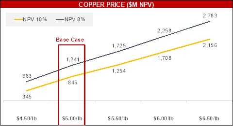
Figure 22-2: Base Case - Sensitivity to Concentrator Process Plant Growth Capital by 5% Increments
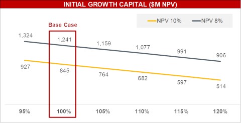
|
Figure 22-3: Base Case - Sensitivity to Discount Rate
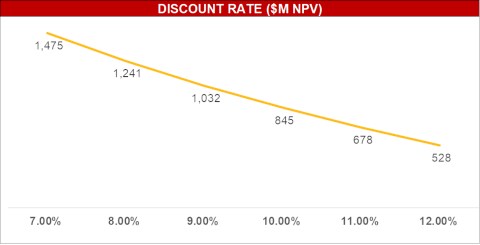
Table 22-3: Key Metrics of the Financial Analysis - Base Case Sensitivity Analysis
| Sensitivity Analysis Base Case | ||||||
| Copper Price | Unit | $4.50/lb | $5.00/lb | $5.50/lb | $6.00/lb | $6.50/lb |
| Net present value1 @ 8% | $ millions | $663 | $1,241 | $1,725 | $2,258 | $2,783 |
| Net present value1 @ 10% | $ millions | $345 | $845 | $1,254 | $1,708 | $2,156 |
| Internal rate of return1 | % | 12.9% | 16.8% | 19.5% | 22.5% | 25.2% |
| Payback period | # years | 5.9 | 5.4 | 5.1 | 4.8 | 4.5 |
| EBITDA (annual avg.)2 | $ millions | $471 | $566 | $652 | $742 | $833 |
Notes: 1. Net present value and internal rate of return are shown on an after-tax basis. 2. EBITDA is a non-GAAP financial performance measure with no standardized definition under IFRS. For further information, please refer to the company's most recent Management's Discussion and Analysis for the three and six months ended June 30, 2026.
22.3.2 Extension Case - Sensitivity to Key Input Parameters on the Financial Model
As with the Base Case, an important model input for the Extension Case is the copper price as copper constitutes approximately 93% of revenue. To assess the sensitivity, six price scenarios were examined, as illustrated in Figure 22-4. Two other parameters were considered for the sensitivity study: growth capital and discount rate (Figure 22-5 and Figure 22-6).
|
Figure 22-4: Extension Case - Sensitivity to Copper Price
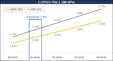
Figure 22-5: Extension Case - Sensitivity to Concentrator Process Plant Growth Capital by 5% Increments
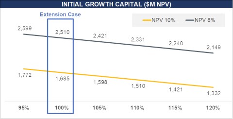
|
Figure 22-6: Extension Case - Sensitivity to Discount Rate
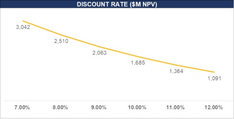
Table 22-4: Extension Case - Key Metrics of the Financial Analysis - Sensitivity Analysis
| Sensitivity Analysis | ||||||
| Copper Price | Unit | $4.50/lb | $5.00/lb | $5.50/lb | $6.00/lb | $6.50/lb |
| Net present value1 @ 8% | $ millions | $1,702 | $2,510 | $3,225 | $3.983 | $4,726 |
| Net present value1 @ 10% | $ millions | $1,033 | $1,685 | $2,247 | $2,851 | $3,440 |
| Internal rate of return1 | % | 15.5% | 18.8% | 21.2% | 23.9% | 26.3% |
| Payback period | # years | 5.9 | 5.4 | 5.1 | 4.8 | 4.5 |
| EBITDA (annual avg.)2 | $ millions | $433 | $522 | $608 | $695 | $782 |
Notes: 1. Net present value and internal rate of return are shown on an after-tax basis. 2. EBITDA is a non-GAAP financial performance measure with no standardized definition under IFRS. For further information, please refer to the company's most recent Management's Discussion and Analysis for the three and six months ended June 30, 2026.
22.4 Key Model Assumptions
The following subsection details the key assumptions used in the Project cash flow model and applies to the Base Case and the Extension Case.
22.4.1 Valuation Approach
All inputs are real 2026 US dollars discounted at real rates of return of 8% and 10% to determine the after-tax NPV. The discount rates are based on an assumed weighted average cost of capital plus a low and high case of additional premiums added to account for project-specific risk factors. The annual cash flows are discounted using a full-year assumption to the valuation date at Project start on October 1, 2026.
|
22.4.2 Processing
For the first four years of the mine life, mill feed is processed into copper and molybdenum concentrates at a daily processing capacity of 60 kstpd. The IPCC investment is planned for Year 3 of operations to optimize hauling and rehandling costs as the mine operations approach the East Pit. The concentrator expansion investment is planned for Year 4 of operations to expand the daily processing capacity to 90 kstpd, incorporating additional equipment and construction. The IPCC and the concentrator expansion are based on pre-feasibility level engineering, their capital cost estimates are subject to a higher degree of uncertainty than the initial growth capital, and each will require amendments to existing permits that have not yet been obtained. Based on the assumptions in the cash flow model, the Project is expected to generate sufficient free cash flow in Years 1 to 3 to fully fund the expansion without the need for additional financing.
22.4.3 Metal Price & Other Marketing Assumptions
The metal price and other marketing assumptions used in this economic evaluation have been detailed in Table 19-1 and Table 19-2 with the supporting assumptions discussed as well in Section 19 of this Technical Report.
22.4.4 Royalty
A net smelter return (NSR) royalty of 3.0% exists on substantially all of the property from which the minerals are contemplated to be extracted and is included in the economic analysis. The calculation of the royalty includes revenues from the sale of products processed from internally mined resources, assumes gold and silver is sold at the market price, and deducts offsite costs.
22.4.5 Stream
Precious metals production from the Project is subject to a stream agreement with Wheaton Precious Metals International Ltd. ("Wheaton"). Under the Wheaton stream agreement, Hudbay (BVI) International Inc. ("Hudbay BVI") is entitled to receive an initial deposit of $230M (subject to the satisfaction of certain conditions) against delivery of 92.5% of the gold and silver contained in the mineral products produced from the Project (other than any gold production that is less than 1g/t in concentrate during the first four years of operation), at fixed gold and silver prices of 15% of the market price. In addition, a contingent payment of up to $70M is payable to Hudbay BVI upon completion of the concentrator expansion to 90 kstpd by the fifth anniversary of commercial production, provided that a reduced contingent payment will nonetheless be payable if such expansion is completed by the tenth anniversary of commercial production. Hudbay BVI has entered into a stream agreement with Copper World LLC on substantially the same terms as the Wheaton stream agreement.
22.4.6 Federal & State Taxes
Taxable income for federal income tax purposes is defined as cash revenues minus offsite costs, operating costs, royalties, tax depreciation, depletion, state taxes, and net operating loss (NOL) carry forwards. Taxable income is multiplied by the prevailing federal tax rate of 21% and state tax rate of 4.68% to determine cash taxes payable. Cash taxes are assumed paid in the year incurred. Tax depreciation rates are shown below in Table 22-5.
|
Table 22-5: Income Tax Depreciation Rates
| Year | Mine Dev | Project | Sustaining | Capital Explor | Infrastructure |
| 1 | 100.00% | 14.29% | 14.29% | 5.00% | 3.13% |
| 2 | - | 24.49% | 24.49% | 10.00% | 6.25% |
| 3 | - | 17.49% | 17.49% | 10.00% | 6.25% |
| 4 | - | 12.49% | 12.49% | 10.00% | 6.25% |
| 5 | - | 8.93% | 8.93% | 10.00% | 6.25% |
| 6 | - | 8.92% | 8.92% | 10.00% | 6.25% |
| 7 | - | 8.93% | 8.93% | 10.00% | 6.25% |
| 8 | - | 4.46% | 4.46% | 10.00% | 6.25% |
| 9 | - | - | - | 10.00% | 6.25% |
| 10 | - | - | - | 10.00% | 6.25% |
| 11 | - | - | - | 5.00% | 6.25% |
| 12 | - | - | - | - | 6.25% |
| 13 | - | - | - | - | 6.25% |
| 14 | - | - | - | - | 6.25% |
| 15 | - | - | - | - | 6.25% |
| 16 | - | - | - | - | 6.25% |
| 17 | - | - | - | - | 3.12% |
State severance and property taxes are calculated using applicable rates shown below in Table 22-6. Property tax is modeled utilizing the cost approach, for the first and last five years of the mine life, and a 50/50 pro rata split between income and cost approaches for the intervening years.
Table 22-6: Other Tax Assumptions
| Metric | Unit | Phase I |
| Federal Income Tax | ||
| Income tax rate | % | 21.00% |
| Depletion - Federal rate - Copper, Gold, Silver | % | 15.00% |
| Depletion - Federal rate - Molybdenum | % | 22.00% |
| Depletion - net income limitation | % | 50.00% |
| State Income Tax | ||
| Income tax rate | % | 4.68% |
| Basis rate | % | 50.00% |
| Severance tax rate | % | 2.50% |
| Property Tax | ||
| Discount rate | % | 13.93% |
| Assessment ratio | % | 15.00% |
| Estimated primary tax rate | % | 12.89% |
| Income taxes allowed | % | 21.00% |
| Capex deduction per year | % | 10.00% |
22.4.7 Working Capital Changes
Working capital for accounts receivable and accounts payable will vary over the mine life based on revenue, operating costs, and capital costs. The turnover rate is 30 days for accounts receivable and 60 days for accounts payable, based on a five-year average of actual results at Hudbay's North American business units adjusted to account for expected accelerated payments to prime contractors under the Arizona Prompt Pay Act. Finished goods inventory turnover is not modeled as production is assumed to equal sales.
|
All the working capital is assumed to be recaptured by the end of the mine life and the closing value of the accounts is zero. First fills of consumables and other operating supplies are included in Project capital.
22.5 Base Case Production Profile & Cost of Production
The annual copper production profile over the LOM in the base case, reflects the concentrator operating at 60 kstpd with an average annual copper production of 71,000 tonnes in Year 1 to Year 4, followed by an expansion to 90 kstpd in Year 5 (which remains subject to pre-feasibility level engineering and additional permitting, as described in Section 22.4.2) with an average annual copper production increasing to 122,000 tonnes between Year 5 and Year 12. Production averages on an annual basis at a cash cost and sustaining cash cost of $1.70/lb. and $2.21/lb. of copper, respectively (Figure 22-7).
Figure 22-7: Base Case Copper Production Profile and Sustaining Cash Costs
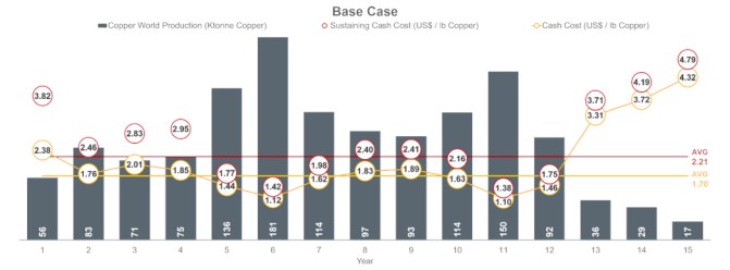
22.6 Extension Case Production Profile & Cost of Production
The annual copper production profile over the LOM in the Extension Case also reflects the concentrator operating at 60 kstpd with an average annual copper production of 71,000 tonnes in Year 1 to Year 4 followed by the concentrator expansion to 90 kstpd in Year 5 with an average annual copper production increasing to 107,000 tonnes between Year 5 and Year 30. Production in the Extension Case after Year 10 assumes that Copper World obtains federal permits for the extension of mining activities onto federal lands, which process has not been initiated, and that the concentrator expansion is completed as described in Section 22.4.2.
Production averages on an annual basis at a cash cost and sustaining cash cost of $1.94/lb. and $2.38/lb. of copper, respectively (Figure 22-8).
|
Figure 22-8: Extension Case Copper Production Profile and Sustaining Cash Costs
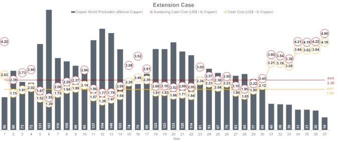
22.7 Details of the Base Case Economic Model & Cash Flow Profile
A summary of the annual cash flows, capital and cumulative cash balance in the Base Case is presented in Figure 22-9, and the details of the Base Case cash flow model are presented in Table 22-9.
The life of mine cash flow in the Base Case shows that the Project generates on average $403M annual net cash flow from Years 1 to 15. The payback period on the project is 5.4 years including the expansion growth capital. From Year 5 to Year 12, the Project generates an average annual net cash flow of $690M and a cash balance of over $4 billion at the end of mine life.
22.8 Details of the Extension Case Economic Model & Cash Flow Profile
A summary of the annual cash flows, capital and cumulative cash balance in the Extension Case is presented in Figure 22-10, and the details of the Extension Case cash flow model are presented in Table 22-2, Table 22-10 and Table 22-11.
The life of mine cash flow in the Extension Case shows that the Project generates on average $371M annual net cash flow from Years 1 to 37. The payback period on the project is 5.4 years including the expansion growth capital (not including the filtered tailings growth capital in Years 10 and 11). The Project generates a cash balance of over $11 billion at the end of mine life.
|
Figure 22-9: Base Case LOM Cash Flow Profile
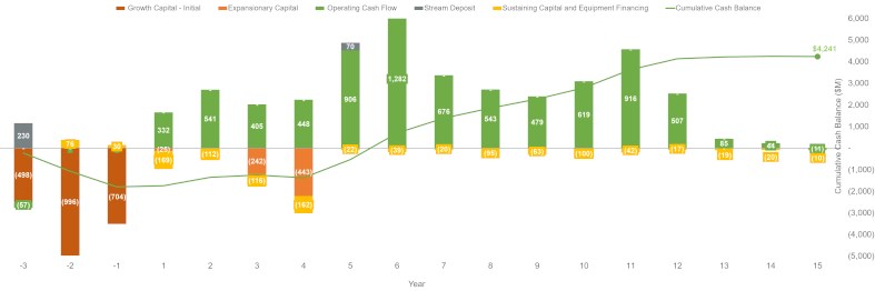
|
Table 22-7: Base Case Cash Flow Model - Physicals
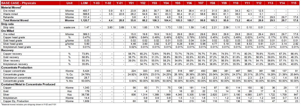
Table 22-8: Base Case Cash Flow Model - Unit Costs

|
Table 22-9: Base Case Cash Flow Model - Cash Flows
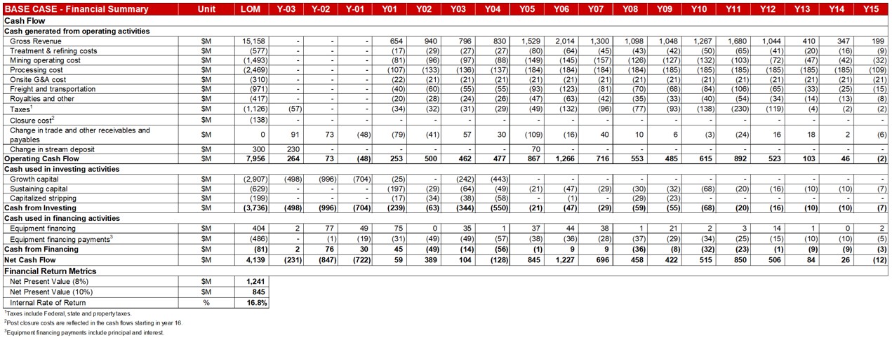
|
Figure 22-10: Extension Case LOM Cash Flow Profile
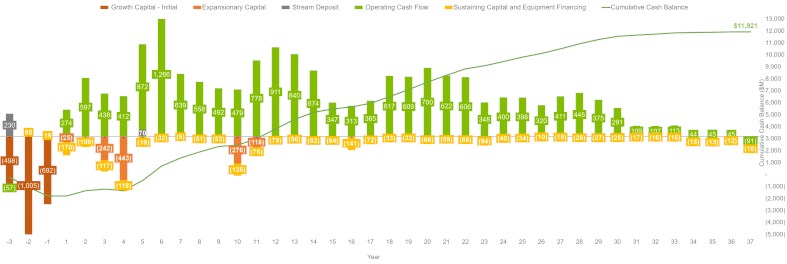
|
Table 22-10: Extension Case Cash Flow Model - Physicals
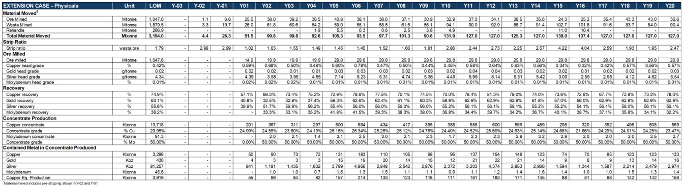
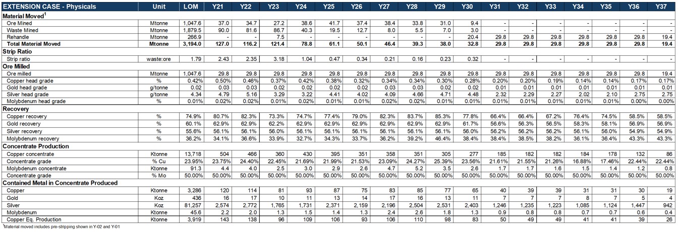
Table 22-11: Extension Case Cash Flow Model - Unit Costs
|


Table 22-12: Extension Case Cash Flow Model - Cash Flows
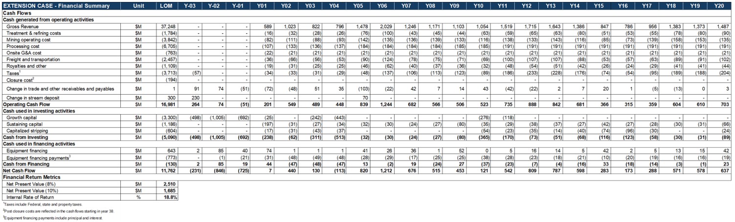
|
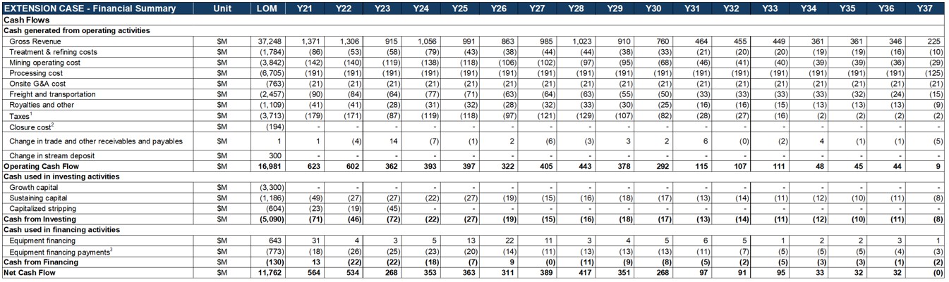
|
23 ADJACENT PROPERTIES
This section is not relevant to this report.
|
24 OTHER RELEVANT DATA & INFORMATION
24.1 Extension Case Mine Plan
This Technical Report also presents certain material information in respect of an Extension Case based on pre-feasibility level work and measured and indicated mineral resource estimates only, which contemplates an extension of mine activities onto Copper World's Unpatented Claims and associated federal lands in Year 10 and a mine life of 37 years (plus two years of pre-stripping). The Extension Case mine plan would require Copper World to apply for and obtain federal permits prior to Year 10 and is not the selected development option in this Technical Report. The Extension Case is intended to illustrate the full potential of the Project and in the opinion of the author constitutes other relevant data that should be included in this Technical Report.
The measured and indicated mineral resources that support the Extension Case are part of the total measured and indicated mineral resource estimates presented in Section 14 of the Technical Report. They are however restricted to only the portion that could be included in an economic pit design excluding inferred mineral resource estimates, i.e. inferred mineral resource estimates were considered as waste.
The mining and recovery methods for the Extension Case are substantially the same as those presented for the Base Case in Sections 16 and 17 of the Technical Report. Both scenarios share the same fundamental modifying factors, mine design criteria, and operating assumptions. In both cases, the initial production sequence prioritizes higher-grade ore and lower strip ratios to accelerate capital payback and minimize early-stage waste movement.
Overall, the plan consists of 77% Measured mineral resources and 23% Indicated mineral resources. Mineral resources that are not mineral reserves do not have demonstrated economic viability.
The capital and operating costs and economic analysis for the Extension Case are presented in Sections 21 and 22, respectively, of the Technical Report.
24.1.1 Extension Case Mine Schedule and Production Plan
Under the Extension Case, the mine operation features a 37-year LOM plus two years of pre-production stripping. The LOM production plan delivers 1,155 million tons of mill feed and requires the removal of approximately 2,072 million tons of waste, resulting in an overall LOM strip ratio of 1.8:1.
As for the Base Case, the production sequence prioritizes higher-grade material at lower strip ratios in the early years to strengthen near-term economics and accelerate capital payback. This phased development approach minimizes initial waste movement while operations remain spatially. As the mine matures and transitions to the off-lease pushback, waste stripping is sequenced to maintain adequate ore exposure, ensuring a consistent and reliable mill feed throughout the LOM. To support this Extended LOM Scenario, mine facilities will be expanded beyond the exterior boundary and design that requires only state and local permits to achieve and sustain a peak total material movement capacity beginning in Year 10.
|
Table 24-1: Extension Case Mining Schedule
| Period | YRPP-2 | YRPP-1 | YR01 | YR02 | YR03 | YR04 | YR05 | YR06 | YR07 | YR08 | YR09 | YR10 | YR11 | YR12 | YR13 | YR14 | YR15 | YR16 | YR17 | YR18 | |
| Mining | Ore Tons ('000s) | 1,231 | 7,276 | 28,128 | 41,877 | 43,185 | 40,223 | 44,955 | 41,984 | 42,525 | 40,901 | 34,108 | 36,229 | 40,745 | 37,558 | 42,493 | 39,200 | 26,805 | 27,753 | 39,044 | 47,766 |
| PE | 1,059 | 1,445 | 14,900 | 1,354 | 0 | 0 | 0 | 0 | 0 | 0 | 0 | 11,514 | 0 | 0 | 0 | 9,826 | 6,551 | 16,848 | 0 | 316 | |
| WP | 107 | 4,872 | 11,177 | 13,700 | 6,103 | 5,534 | 0 | 0 | 0 | 0 | 0 | 0 | 0 | 0 | 0 | 0 | 0 | 0 | 0 | 0 | |
| BT | 65 | 960 | 2,051 | 26,823 | 32,242 | 24,107 | 0 | 0 | 0 | 0 | 0 | 0 | 0 | 0 | 0 | 0 | 0 | 0 | 0 | 0 | |
| EP | - | - | - | - | 4,840 | 10,582 | 44,955 | 41,984 | 42,525 | 40,901 | 34,108 | 24,714 | 40,745 | 37,558 | 42,493 | 29,374 | 20,254 | 10,904 | 39,044 | 47,450 | |
| Direct To Mill Tons ('000s) | - | - | 16,470 | 21,900 | 21,900 | 19,854 | 26,744 | 32,494 | 32,190 | 30,043 | 28,909 | 27,444 | 32,850 | 32,850 | 32,850 | 32,850 | 20,700 | 21,400 | 32,850 | 32,850 | |
| To StockPiles Tons ('000s) | 1,231 | 7,276 | 11,658 | 19,977 | 21,285 | 20,368 | 18,211 | 9,490 | 10,335 | 10,858 | 5,199 | 8,784 | 7,895 | 4,708 | 9,643 | 6,350 | 6,105 | 6,353 | 6,194 | 14,916 | |
| Waste Tons ('000s) | 3,669 | 21,723 | 28,682 | 68,123 | 66,815 | 59,777 | 65,045 | 60,759 | 64,465 | 67,935 | 61,871 | 103,771 | 99,255 | 102,442 | 95,595 | 100,800 | 113,195 | 112,247 | 100,956 | 92,234 | |
| PE | 1,441 | 2,420 | 10,213 | 510 | 0 | 0 | 0 | 0 | 0 | 0 | 0 | 23,172 | 0 | 0 | 0 | 7,511 | 2,540 | 5,023 | 0 | 84 | |
| WP | 858 | 5,911 | 6,166 | 8,690 | 1,312 | 594 | 0 | 0 | 0 | 0 | 0 | 0 | 0 | 0 | 0 | 0 | 0 | 0 | 0 | 0 | |
| BT | 1,370 | 13,393 | 12,302 | 58,916 | 19,962 | 9,765 | 0 | 0 | 0 | 0 | 0 | 0 | 0 | 0 | 0 | 0 | 0 | 0 | 0 | 0 | |
| EP | 0 | 0 | 0 | 8 | 45,542 | 49,418 | 65,045 | 60,759 | 64,465 | 67,935 | 61,871 | 80,599 | 99,255 | 102,442 | 95,595 | 93,289 | 110,655 | 107,224 | 100,956 | 92,149 | |
| Mined Tons ('000s) | 4,900 | 29,000 | 56,810 | 110,000 | 110,000 | 100,000 | 110,000 | 102,743 | 106,990 | 108,836 | 95,979 | 140,000 | 140,000 | 140,000 | 138,087 | 140,000 | 140,000 | 140,000 | 140,000 | 140,000 | |
| PE | 2,500 | 3,865 | 25,114 | 1,864 | 0 | 0 | 0 | 0 | 0 | 0 | 0 | 34,686 | 0 | 0 | 0 | 17,337 | 9,091 | 21,872 | 0 | 401 | |
| WP | 965 | 10,782 | 17,343 | 22,390 | 7,415 | 6,128 | 0 | 0 | 0 | 0 | 0 | 0 | 0 | 0 | 0 | 0 | 0 | 0 | 0 | 0 | |
| BT | 1,435 | 14,353 | 14,353 | 85,738 | 52,204 | 33,872 | 0 | 0 | 0 | 0 | 0 | 0 | 0 | 0 | 0 | 0 | 0 | 0 | 0 | 0 | |
| EP | 0 | 0 | 0 | 8 | 50,381 | 60,000 | 110,000 | 102,743 | 106,990 | 108,836 | 95,979 | 105,314 | 140,000 | 140,000 | 138,087 | 122,663 | 130,909 | 118,128 | 140,000 | 139,599 | |
| SR (W:O) | 2.98 | 2.99 | 1.02 | 1.63 | 1.55 | 1.49 | 1.45 | 1.45 | 1.52 | 1.66 | 1.81 | 2.86 | 2.44 | 2.73 | 2.25 | 2.57 | 4.22 | 4.04 | 2.59 | 1.93 | |
| Rehandle Ore Tons ('000s) | 0 | 0 | 0 | 0 | 0 | 2,046 | 6,106 | 356 | 660 | 2,807 | 3,941 | 5,406 | 0 | 0 | 0 | 0 | 12,150 | 11,450 | 0 | 0 | |
| CuSS (%) | 0.00% | 0.00% | 0.00% | 0.00% | 0.00% | 0.20% | 0.20% | 0.17% | 0.20% | 0.08% | 0.08% | 0.13% | 0.00% | 0.00% | 0.00% | 0.00% | 0.08% | 0.08% | 0.00% | 0.00% | |
| Cu (%) | 0.00% | 0.00% | 0.00% | 0.00% | 0.00% | 0.41% | 0.41% | 0.36% | 0.41% | 0.21% | 0.21% | 0.25% | 0.00% | 0.00% | 0.00% | 0.00% | 0.21% | 0.21% | 0.00% | 0.00% | |
| Au (Oz/Ton) | 0 | 0 | 0 | 0 | 0 | 0.0006 | 0.0006 | 0.0005 | 0.0006 | 0.0003 | 0.0003 | 0.0003 | 0 | 0 | 0 | 0 | 0.0004 | 0.0004 | 0 | 0 | |
| Ag (Oz/Ton) | 0 | 0 | 0 | 0 | 0 | 0.1097 | 0.1097 | 0.1001 | 0.1097 | 0.0773 | 0.0773 | 0.083 | 0 | 0 | 0 | 0 | 0.0729 | 0.073 | 0 | 0 | |
| Mo (%) | 0.00% | 0.00% | 0.00% | 0.00% | 0.00% | 0.01% | 0.01% | 0.01% | 0.01% | 0.01% | 0.01% | 0.01% | 0.00% | 0.00% | 0.00% | 0.00% | 0.01% | 0.01% | 0.00% | 0.00% | |
| Total All | Material Moved Tons ('000s) | 4,900 | 29,000 | 56,810 | 110,000 | 110,000 | 102,046 | 116,106 | 103,099 | 107,650 | 111,643 | 99,920 | 145,406 | 140,000 | 140,000 | 138,087 | 140,000 | 152,150 | 151,450 | 140,000 | 140,000 |
|
| Period | YR19 | YR20 | YR21 | YR22 | YR23 | YR24 | YR25 | YR26 | YR27 | YR28 | YR29 | YR30 | YR31 | YR32 | YR33 | YR34 | YR35 | YR36 | YR37 | Grand Total | |
| Mining | Ore Tons ('000s) | 47,450 | 40,357 | 40,826 | 38,235 | 30,017 | 42,531 | 45,938 | 41,279 | 42,332 | 37,271 | 34,184 | 10,350 | 0 | 0 | 0 | 0 | 0 | 0 | 0 | 1,154,756 |
| PE | 0 | 0 | 0 | 0 | 0 | 0 | 0 | 0 | 0 | 0 | 0 | 0 | 0 | 0 | 0 | 0 | 0 | 0 | 0 | 63,814 | |
| WP | 0 | 0 | 0 | 0 | 0 | 0 | 0 | 0 | 0 | 0 | 0 | 0 | 0 | 0 | 0 | 0 | 0 | 0 | 0 | 41,493 | |
| BT | 0 | 0 | 0 | 0 | 0 | 0 | 0 | 0 | 0 | 0 | 0 | 0 | 0 | 0 | 0 | 0 | 0 | 0 | 0 | 86,248 | |
| EP | 47,450 | 40,357 | 40,826 | 38,235 | 30,017 | 42,531 | 45,938 | 41,279 | 42,332 | 37,271 | 34,184 | 10,350 | - | - | - | - | - | - | - | 963,201 | |
| Direct To Mill Tons ('000s) | 32,850 | 32,850 | 32,850 | 32,850 | 24,628 | 32,850 | 32,850 | 32,850 | 32,850 | 32,850 | 32,850 | 10,313 | - | - | - | - | - | - | - | 860,588 | |
| To StockPiles Tons ('000s) | 14,600 | 7,507 | 7,976 | 5,385 | 5,390 | 9,681 | 13,088 | 8,429 | 9,482 | 4,421 | 1,334 | 37 | 0 | 0 | 0 | 0 | 0 | 0 | 0 | 294,168 | |
| Waste Tons ('000s) | 92,550 | 99,643 | 99,174 | 89,894 | 95,557 | 44,381 | 21,454 | 13,949 | 8,783 | 6,091 | 7,710 | 3,286 | 0 | 0 | 0 | 0 | 0 | 0 | 0 | 2,071,831 | |
| PE | 0 | 0 | 0 | 0 | 0 | 0 | 0 | 0 | 0 | 0 | 0 | 0 | 0 | 0 | 0 | 0 | 0 | 0 | 0 | 52,915 | |
| WP | 0 | 0 | 0 | 0 | 0 | 0 | 0 | 0 | 0 | 0 | 0 | 0 | 0 | 0 | 0 | 0 | 0 | 0 | 0 | 23,531 | |
| BT | 0 | 0 | 0 | 0 | 0 | 0 | 0 | 0 | 0 | 0 | 0 | 0 | 0 | 0 | 0 | 0 | 0 | 0 | 0 | 115,707 | |
| EP | 92,550 | 99,643 | 99,174 | 89,894 | 95,557 | 44,381 | 21,454 | 13,949 | 8,783 | 6,091 | 7,710 | 3,286 | 0 | 0 | 0 | 0 | 0 | 0 | 0 | 1,879,678 | |
| Mined Tons ('000s) | 140,000 | 140,000 | 140,000 | 128,129 | 125,574 | 86,912 | 67,392 | 55,227 | 51,115 | 43,361 | 41,895 | 13,636 | 0 | 0 | 0 | 0 | 0 | 0 | 0 | 3,226,587 | |
| PE | 0 | 0 | 0 | 0 | 0 | 0 | 0 | 0 | 0 | 0 | 0 | 0 | 0 | 0 | 0 | 0 | 0 | 0 | 0 | 116,729 | |
| WP | 0 | 0 | 0 | 0 | 0 | 0 | 0 | 0 | 0 | 0 | 0 | 0 | 0 | 0 | 0 | 0 | 0 | 0 | 0 | 65,024 | |
| BT | 0 | 0 | 0 | 0 | 0 | 0 | 0 | 0 | 0 | 0 | 0 | 0 | 0 | 0 | 0 | 0 | 0 | 0 | 0 | 201,955 | |
| EP | 140,000 | 140,000 | 140,000 | 128,129 | 125,574 | 86,912 | 67,392 | 55,227 | 51,115 | 43,361 | 41,895 | 13,636 | 0 | 0 | 0 | 0 | 0 | 0 | 0 | 2,842,879 | |
| SR (W:O) | 1.95 | 2.47 | 2.43 | 2.35 | 3.18 | 1.04 | 0.47 | 0.34 | 0.21 | 0.16 | 0.23 | 0.32 | 0 | 0 | 0 | 0 | 0 | 0 | 0 | 1.79 | |
| Rehandle Ore Tons ('000s) | 0 | 0 | 0 | 0 | 8,222 | 0 | 0 | 0 | 0 | 0 | 0 | 22,537 | 32,850 | 32,850 | 32,850 | 32,850 | 32,850 | 32,850 | 21,386 | 294,168 | |
| CuSS (%) | 0.00% | 0.00% | 0.00% | 0.00% | 0.08% | 0.00% | 0.00% | 0.00% | 0.00% | 0.00% | 0.00% | 0.06% | 0.10% | 0.10% | 0.09% | 0.03% | 0.04% | 0.11% | 0.11% | 0.08% | |
| Cu (%) | 0.00% | 0.00% | 0.00% | 0.00% | 0.22% | 0.00% | 0.00% | 0.00% | 0.00% | 0.00% | 0.00% | 0.20% | 0.20% | 0.20% | 0.19% | 0.14% | 0.14% | 0.17% | 0.17% | 0.19% | |
| Au (Oz/Ton) | 0 | 0 | 0 | 0 | 0.0005 | 0 | 0 | 0 | 0 | 0 | 0 | 0.0005 | 0.0004 | 0.0004 | 0.0004 | 0.0004 | 0.0004 | 0.0003 | 0.0003 | 0.0004 | |
| Ag (Oz/Ton) | 0 | 0 | 0 | 0 | 0.0664 | 0 | 0 | 0 | 0 | 0 | 0 | 0.069 | 0.0675 | 0.0669 | 0.0663 | 0.0588 | 0.0611 | 0.0802 | 0.0802 | 0.0703 | |
| Mo (%) | 0.00% | 0.00% | 0.00% | 0.00% | 0.01% | 0.00% | 0.00% | 0.00% | 0.00% | 0.00% | 0.00% | 0.01% | 0.01% | 0.01% | 0.01% | 0.01% | 0.01% | 0.00% | 0.00% | 0.01% | |
| Total All | Material Moved Tons ('000s) | 140,000 | 140,000 | 140,000 | 128,129 | 133,796 | 86,912 | 67,392 | 55,227 | 51,115 | 43,361 | 41,895 | 36,173 | 32,850 | 32,850 | 32,850 | 32,850 | 32,850 | 32,850 | 21,386 | 3,520,755 |
|
The schedule accounts for a total of 3,227 million tons of material mined over the active mining period. This consists of 1,155 million tons of ore and 2,072 million tons of waste. Total material mined ramps up progressively, reaching a sustained peak capacity of 140,000 ktons per year from Year 10 through Year 21.
Early production is heavily supported by the BT and PE pits, particularly in Years 1 through 4. The WP pit provides a steady contribution throughout the first half of the mine life. The EP pit becomes the dominant source of material starting around Year 5 and is the exclusive source of mined material from Year 18 until active mining ceases in Year 30.
Following pre-production (YRPP-2, YRPP-1), the mill feed ramps up over the first three years. By Year 4, total mill feed stabilizes at a consistent nameplate capacity of approximately 32,850 kst (33 million tons) per year, maintaining this level through Year 36 before a partial year in Year 37.
Figure 24-1: Extension Case: Material Mined by Source by Year
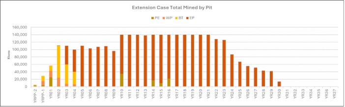
As Illustrated in Figure 24-2 ore sources are as follows:
• Years 1 to 30: Mill feed is predominantly Run-of-Mine (ROM) direct from the pit (blue bars), with periodic supplements from stockpiles (green bars) to maintain full mill capacity (e.g., Years 7-10 and 15-16).
• Years 31 to 37: Direct ROM feed completely ceases, indicating the end of active mining. For the final seven years, the mill operates exclusively by reclaiming low-grade stockpiled material (green bars).
|
Figure 24-2: Extension Case: Plant Feed Mill Tonnages by Year
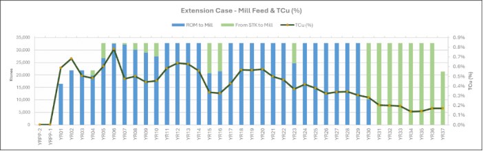
The mining sequence clearly prioritizes higher-grade material early in the mine life. The copper grade peaks at 0.78% in Year 6 and sees another minor peak at 0.64% in Year 12. As the mine matures, the grade steadily declines, dropping significantly to between 0.14% and 0.20% during the final stockpile-reclaim phase (Years 31-37).
The yearly breakdown shows that Measured resources form the vast majority of the mined ore for most of the production years (Figure 24-3).
Figure 24-3: Extension Case: Mineral Resource Category by Year
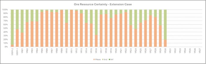
|
Table 24-2: Extension Case Mill Feed Schedule
| Period | YR01 | YR02 | YR03 | YR04 | YR05 | YR06 | YR07 | YR08 | YR09 | YR10 | YR11 | YR12 | YR13 | YR14 | YR15 |
| Mill Tons ('000s) | 16,470 | 21,900 | 21,900 | 21,900 | 32,850 | 32,850 | 32,850 | 32,850 | 32,850 | 32,850 | 32,850 | 32,850 | 32,850 | 32,850 | 32,850 |
| CuSS (%) | 0.20% | 0.19% | 0.12% | 0.10% | 0.13% | 0.08% | 0.08% | 0.14% | 0.09% | 0.14% | 0.07% | 0.07% | 0.06% | 0.09% | 0.08% |
| Cu (%) | 0.59% | 0.68% | 0.50% | 0.48% | 0.60% | 0.78% | 0.47% | 0.50% | 0.44% | 0.45% | 0.58% | 0.64% | 0.63% | 0.56% | 0.34% |
| Au (Oz/Ton) | 0.0006 | 0.0005 | 0.0004 | 0.0003 | 0.0008 | 0.0009 | 0.0010 | 0.0007 | 0.0007 | 0.0006 | 0.0010 | 0.0011 | 0.0010 | 0.0007 | 0.0005 |
| Ag (Oz/Ton) | 0.1281 | 0.1043 | 0.1151 | 0.1326 | 0.2082 | 0.2692 | 0.1548 | 0.1382 | 0.1565 | 0.1309 | 0.1739 | 0.2375 | 0.1549 | 0.1581 | 0.0874 |
| Mo (%) | 0.02% | 0.02% | 0.02% | 0.01% | 0.01% | 0.01% | 0.01% | 0.01% | 0.01% | 0.01% | 0.01% | 0.01% | 0.01% | 0.01% | 0.01% |
| Cu Content (tons) | 96,816 | 149,840 | 110,190 | 105,355 | 197,921 | 256,500 | 155,838 | 164,442 | 144,584 | 149,066 | 192,099 | 208,886 | 205,798 | 183,200 | 110,080 |
| Mo Content (tons) | 2,498 | 3,303 | 3,425 | 2,148 | 4,078 | 3,342 | 4,268 | 3,057 | 3,273 | 2,590 | 3,630 | 3,209 | 4,575 | 4,730 | 3,954 |
| Cum Mill Tons ('000s) | 16,470 | 38,370 | 60,270 | 82,170 | 115,020 | 147,870 | 180,720 | 213,570 | 246,420 | 279,270 | 312,120 | 344,970 | 377,820 | 410,670 | 443,520 |
|
Period |
YR16 |
YR17 |
YR18 |
YR19 |
YR20 |
YR21 |
YR22 |
YR23 |
YR24 |
YR25 |
YR26 |
YR27 |
YR28 |
YR29 |
YR30 |
YR31 |
YR32 |
YR33 |
YR34 |
YR35 |
YR36 |
YR37 |
Grand Total |
|
Mill Tons ('000s) |
32,850 |
32,850 |
32,850 |
32,850 |
32,850 |
32,850 |
32,850 |
32,850 |
32,850 |
32,850 |
32,850 |
32,850 |
32,850 |
32,850 |
32,850 |
32,850 |
32,850 |
32,850 |
32,850 |
32,850 |
32,850 |
21,386 |
1,154,756 |
|
CuSS (%) |
0.09% |
0.16% |
0.13% |
0.10% |
0.06% |
0.04% |
0.03% |
0.08% |
0.08% |
0.06% |
0.04% |
0.02% |
0.02% |
0.01% |
0.05% |
0.10% |
0.10% |
0.09% |
0.03% |
0.04% |
0.11% |
0.11% |
0.08% |
|
Cu (%) |
0.32% |
0.42% |
0.57% |
0.56% |
0.57% |
0.50% |
0.46% |
0.37% |
0.42% |
0.38% |
0.32% |
0.34% |
0.34% |
0.30% |
0.28% |
0.20% |
0.20% |
0.19% |
0.14% |
0.14% |
0.17% |
0.17% |
0.42% |
|
Au (Oz/Ton) |
0.0003 |
0.0004 |
0.0006 |
0.0007 |
0.0008 |
0.0008 |
0.0008 |
0.0005 |
0.0005 |
0.0006 |
0.0007 |
0.0008 |
0.0008 |
0.0006 |
0.0005 |
0.0004 |
0.0004 |
0.0004 |
0.0004 |
0.0004 |
0.0003 |
0.0003 |
0.0006 |
|
Ag (Oz/Ton) |
0.0756 |
0.0861 |
0.1203 |
0.1346 |
0.1615 |
0.1398 |
0.1505 |
0.0959 |
0.0940 |
0.1287 |
0.1172 |
0.1192 |
0.1359 |
0.1374 |
0.1306 |
0.0675 |
0.0669 |
0.0663 |
0.0588 |
0.0611 |
0.0802 |
0.0802 |
0.1266 |
|
Mo (%) |
0.01% |
0.01% |
0.01% |
0.01% |
0.01% |
0.02% |
0.02% |
0.01% |
0.02% |
0.01% |
0.01% |
0.02% |
0.02% |
0.01% |
0.01% |
0.01% |
0.01% |
0.01% |
0.01% |
0.01% |
0.00% |
0.00% |
0.01% |
|
Cu Content (tons) |
106,353 |
139,082 |
186,680 |
185,290 |
188,737 |
163,463 |
152,436 |
121,481 |
137,677 |
123,821 |
105,320 |
110,808 |
112,254 |
100,140 |
92,510 |
66,296 |
65,020 |
63,401 |
44,837 |
46,007 |
55,722 |
36,276 |
4,834,227 |
|
Mo Content (tons) |
2,793 |
3,035 |
4,643 |
4,111 |
4,631 |
7,078 |
6,063 |
4,123 |
5,132 |
4,614 |
4,221 |
7,169 |
7,280 |
4,188 |
3,769 |
2,473 |
2,392 |
2,379 |
2,228 |
2,152 |
1,518 |
988 |
139,057.42 |
|
Cum Mill Tons ('000s) |
32,850 |
65,700 |
98,550 |
131,400 |
164,250 |
197,100 |
229,950 |
262,800 |
295,650 |
328,500 |
361,350 |
394,200 |
427,050 |
459,900 |
492,750 |
525,600 |
558,450 |
591,300 |
624,150 |
657,000 |
689,850 |
711,236 |
711,236 |
|
24.1.2 Extension Case Mining Structures
Modifications to the mine facility layout and utilization under the Extension Case, as compared to the Base Case, include the following key changes:
• TSF-1: Tailings deposition will conclude at the end of Year 10, rather than in Year 15.
• TSF-2: Cyclone overflow deposition will conclude at the end of Year 10, rather than midway through Year 11.
• TSF-SE and TSF-NW: These facilities will replace the TSF-N facility tentatively planned in Base Case.
• Waste Rock Facility (WRF): The WRF is expanded to add the WRF East, providing an estimated additional design capacity for a total of 1.9 Bst.
• ROM Stockpiles: The Run-of-Mine (ROM) ore segregation stockpiles are expanded to include a new South stage, providing an additional capacity of 75 Mst to accommodate the peak projected inventory of 242 Mst in Year 30.
24.1.3 Extension Case Permitting Requirements
The major authorization for the Extension Case will include the submittal of a Mine Plan of Operations (MPO) for use of United States Forest Service (USFS) and Bureau of Land Management (BLM) lands. The Extension Case will be subject to the National Environmental Policy Act (NEPA) process and the preparation of an Environmental Impact Statement (EIS) and Final Record of Decision (ROD), and is eligible for the FAST-41 permit management oversight program.
In addition, studies typical of major federal action will necessitate that reviews be conducted for endangered species, archaeological and cultural resources (many of which have already been conducted), visual resources and related socioeconomic considerations, among others. Federal Tribal consultation also will be required, which typically is supplemented by proponent efforts to interact with and cooperate with Tribal communities and sovereigns.
State of Arizona environmental permits and approvals issued for Base Case, such as for the Class II air permit, APP and Mine Inspector approval, will need to be amended to conform with the mine and operations plans anticipated for the Extension Case. Submittal of the amendments for review by State agencies will be timed to accommodate both the federal process and the anticipated timing of approvals. Authorizations for water and power line routing will remain valid for the Extension Case.
For the Extension Case, a biological assessment (BA) will be developed that will detail potential impacts to species based on the Copper World Project. A new or updated Biological Opinion (BO) will be developed by the USFWS based on the BA and will state whether the Project would or would not jeopardize the existence of any listed species and would or would not destroy designated critical habitat for any listed species. Updated biological surveys will be conducted on federal as well as undisturbed private lands as part of the Extension Case permitting process.
In addition, the federal agencies will need to consult with affected tribes regarding impacts to the tribes, including impacts to cultural resources. As a result of consultation, it is presumed that a new or amended HPTP will be developed for cultural resources on federal lands and any other lands outside of the Base Case disturbance limits. Surveys will be conducted on all federal or other lands (i.e., private, state) as applicable for cultural resources prior to development of the HPTP.
|
Several of the permits described above will include public comment processes where interested stakeholders will be encouraged to share their views on the Project. In addition, Hudbay intends to engage key stakeholders to solicit their input directly. This information will then be used to develop an effective mitigation plan. Specific details of that plan will be determined as the Project progresses and the community is engaged, but a cost allowance is included in the financial model for the Project.
Additional mitigation measures and other social commitments will be determined during development of the Extension Case of the Project.
The tailings facility constructed on the east side of the Santa Rita Mountains for the Extension Case will use dry stack tailings technology. Stormwater run-on and run-off controls will be constructed and stormwater ponding on the surface of the dry stack will be limited during operations. Concurrent reclamation of the outer slopes of the dry stack is also anticipated during operations.
At closure, a final growth media cover will be placed on the top surface of the dry stack and revegetated. The top surface will be graded as needed to route stormwater off the facility and into natural drainages. This will limit the potential for infiltration into the tailings mass from precipitation events.
24.2 Concentrate Leach Option
The 2023 PFS included a concentrate leach facility that would produce copper cathodes at site. Although the concentrate leach facility has been removed from the Base Case and Extension Case presented in this Technical Report, the Project design and layout have retained the flexibility to implement a concentrate leach facility in the future and significant additional work has been done to establish its technical viability. Given this optionality, in the opinion of the author, information related to the concentrate leach option constitutes other relevant data that should be included in this Technical Report.
Parallel to the Copper World Feasibility Study, Hudbay Minerals conducted a Pre-Feasibility Study (PFS) to evaluate four process options for incorporating a Concentrate Leach Facility (CLF) into the Copper World Project. The study confirmed the technical viability of the general CLF strategy. Prior to initiating the CLF Feasibility Study, Hudbay will undertake a bridging phase to complete supplemental metallurgical testing and execute trade-off studies to refine the design basis. The resulting data will be incorporated into a PFS Addendum to complete option evaluations and freeze a single, robust process flowsheet for the Definitive Feasibility Study.
24.2.1 Concentrate Leach Testing
24.2.1.1 Amenability Testwork
The amenability of Copper World concentrate to oxidative leaching via the Albion Process™ (Albion), and low and high temperature pressure oxidation (LT-POX and HT-POX) was previously tested at SGS Lakefield and reported in the Pre-Feasibility Study1. Testing was performed on four low-grade copper world concentrates as well as concentrate from Hudbay's Constancia operation (Peru) to evaluate the opportunity to use Constancia concentrate as a proxy for Copper World for ongoing Albion optimisation work. The tests indicated comparably high Cu extraction (97 % to 100 %) across all samples in Albion and HT-POX, whereas LT-POX resulted in relatively poor extraction. Albion was selected as the preferred concentrate leach technology due to its simplicity, flexibility to scale the plant, and lower acid neutralization requirements. Results of this prefeasibility test program are summarized in Table 24-3.
1 Hudbay Minerals Inc., (2023), NI 43-101 Technical Report, Phase 1 Pre-Feasibility Study and Updated Mineral Resource Estimate, Copper World Project.
|
All samples reached complete extraction between 24 hr and 48 hr. The extraction and kinetic results were comparable between the Copper World and Constancia concentrates, suggesting that Constancia concentrate would be a suitable proxy for Copper World.
Table 24-3: Copper extraction in Albion, LT-POX and HT-POX
| Ore Type | Conc Cu Grade (%) |
Albion (%) |
Albion Foam Adjusted (%) |
LT-POX (%) | HT-POX (%) |
| East Transitional 1 | 11 | 99 | 99 | 85 | 97 |
| East Transitional 2 | 20 | 98 | 99 | 99 | |
| Broad Top Transitional | 10 | 98 | 99 | 89 | 98 |
| Elgin Pit 1 | 10 | 97 | 99 | 96 | 97 |
| Elgin Pit 2 | 16 | 97 | 97 | 99 | |
| Peach Pit | 10 | 94 | 96 | 93 | 97 |
| Constancia 1 | 22 | 75 | 97 | 74 | 100 |
| Constancia 2 | 25 | 65 | 98 | 98 | 89 |
24.2.1.2 Leach Optimisation
Optimisation testwork was undertaken at Core Resources (Brisbane), using Constancia concentrate as a proxy for Copper World concentrate. The Albion testwork aimed to optimise leaching conditions including grind size, chemistry/ free acidity, and residence time. Initial leach tests (AL01 - AL05) were run with a 'standard' starting raffinate, after which tests AL06 - AL13 adopted a representative starting raffinate based on process simulation of the Copper World circuit. The results of the optimisation testwork summarised in Table 24-4.
Table 24-4: Oxidative Leach Parameterisation Conditions and Results
| Parameter | Units | AL01 | AL03 | AL04 | AL05 | AL06 | AL07 | AL08 | AL09 | AL10 | AL11 | AL12 | AL13 |
| Grind Size P80 | µm | 10.2 | 11.9 | 13.9 | 16.0 | 9.8 | 9.8 | 10.0 | 10.0 | 9.7 | 9.7 | 12.0 | 15.9 |
| Raffinate | - | Std | Std | Std | Std | Sim | Sim | Sim | Sim | Sim | Sim | Sim | Sim |
| Solids Density | % w/w | 11.6 | 8.6 | 8.7 | 8.6 | 8.3 | 8.3 | 8.3 | 8.3 | 8.0 | 8.0 | 8.1 | 8.1 |
| Free acidity target | g/L | 15 | 15 | 15 | 15 | 15 | 6 | 15 | 15 | 15 | 15 | 15 | 15 |
| Acid Consumption | kg/t | 834 | 877 | 837 | 779 | 811 | 422 | 857 | 693 | 799 | 810 | 803 | 741 |
| Copper Extraction | |||||||||||||
| 24 h | % | 97.0 | 84.2 | 82.9 | 79.7 | 69.6 | 60.5 | 78.3 | 54.2 | 77.3 | 85.4 | 68.4 | 61.9 |
| 36 h | % | 98.5 | 95.0 | 93.4 | 91.6 | 94.5 | 76.7 | 94.5 | 88.0 | - | - | 87.7 | 82.1 |
| 48 h | % | 98.8 | 97.5 | 97.3 | 95.1 | 97.8 | 90.4 | 98.1 | - | 96.7 | 98.3 | 96.1 | 91.5 |
| 72 h | % | 99.3 | 98.8 | 98.5 | 98.4 | 98.9 | 98.1 | - | - | - | - | - | - |
| Final SOx | % | 85.1 | 79.8 | 82.7 | 83.6 | 81.6 | 73.1 | 78.7 | 66.9 | 73.5 | 73.9 | 69.7 | 65.9 |
|
Optimized process parameters for the Acid Albion Process™ leach were established at a target grind size P80 10 µm (specific energy of 50.2 kWh/t), 15 g/L free acidity and 48-hours residence time. Confirmatory tests under optimal conditions yielded highly reproducible copper recoveries of 97 to 98%, sulfide oxidation between 73 and 79%, and acid consumption of approximately 800 kg/t.
For downstream processing, neutralization using limestone or regional oxide ores (Elgin and Old Dick) successfully precipitated over 90% of soluble iron to well below the 7 g/L solvent extraction threshold, while keeping copper co-precipitation below 4% (over 97% of which was reclaimed during cake washing). Based on solid-liquid separation testing, t pressure filtration is optimal for the leach residue (26% moisture, filtration rate 0.03 st/ft2/h), and vacuum filtration optimal for the iron control discharge (35% moisture, filtration rate 0.01 st/ft2/h).
24.2.2 Concentrate Leach Recovery Method
This sub-section is based on a PFS undertaken by M3 Engineering for a concentrate leach facility using Glencore Technology's Albion Process™. The Albion Process™ comprises two unit operations; fine grinding followed by atmospheric oxidative leaching and is described further in the following sections.
24.2.2.1 Copper Concentrate Leaching
The addition of a concentrate leach facility to treat most of the concentrate (337,858 stpa, 925 stpd, operating 365 days per year at 92 % availability) would allow for finished LME/COMEX registered copper cathodes to be produced on site. The concentrate leach plant is designed to treat a concentrate containing approximately 29% copper and 36 % sulfur. The concentrate leach plant would comprise distinct stages: oxidative leaching, iron removal, solvent extraction and electrowinning.
24.2.2.2 Oxidative Leaching (Albion Process™)
The copper concentrate is loaded via front-end loader into a hopper which discharges onto a feeder that feeds the concentrate re-pulp tank where it is slurried in high-grade raffinate to a target density of approximately 50 % w/w (suitable for grinding in the IsaMill), prior to being pumped to the concentrate storage tank. The concentrate is reground in a stirred mill IsaMill M10000 (4,000 HP) to a P80 of 10 µm prior to the oxidative leach. The IsaMill runs in closed circuit, with fresh feed from the concentrate storage tank being pumped to the IsaMill discharge pumpbox to be mixed with the fine grinding discharge. The combined product is then pumped to the IsaMill cyclone. The underflow from the cyclone reports to the IsaMill feed pumpbox, while the overflow reports to the cyclone overflow tank. The reground copper concentrate is then pumped to the first of eight agitated oxidative leach reactors (62,119 ft3 live volume, 350 HP per tank). Slurry gravitates via launder to each subsequent tank. High-grade raffinate and sulfuric acid (from the acid plant) will be dosed into each reactor to maintain a target free acidity of 12 g/L. Oxygen will be sparged via ring main at the base of each tank to facilitate the oxidation reaction. The process has a 90% oxygen utilization rate at atmospheric pressure and runs at 203 ˚°F for 48 hours to achieve copper extraction to solution greater than 98% and target sulfide oxidation of 78 %. No external heating will be required as the oxidation process is autothermal. The Albion leach discharge gravitates to the feedbox of the Albion Residue Thickener. The thickener overflow (leach solution with extracted copper) is pumped to the iron removal circuit. The thickener underflow is pumped to the Albion Residue Filter where it will be filtered to a target density of approximately 25 % w/w moisture prior to sale to a third party. The leach residue wash water will report to the low grade (LG) PLS tank ahead of the LG SX circuit.
|
The thickener overflow (leach solution with extracted copper) is pumped to the iron removal circuit.
24.2.2.3 Acid Plant
The acid plant will comprise a sulfur burning and acid absorption circuit which incorporates a two-stage tail gas caustic scrubbing system to produce 413,000 stpy 98.5 % purity sulfuric acid, using industry standard equipment.
The sulfuric acid produced is pumped from main storage to dedicated distribution circuits. A portion is transferred to an on-site day tank to continuously supply acid to the Albion Process™ leach plant and copper electrowinning circuit. The remaining commercial production is routed to a multi-station truck loadout facility for off-site transport to third-party consumers.
24.2.2.4 Iron Removal
Overflow from the sulfur tailings thickener is pumped to the first of four agitated iron control tanks (21,199 ft3 live volume per tank). The slurry gravitates to subsequent tanks via launder. Limestone is added to progressively increase the pH in tank from pH < 1 to pH 2.2 to precipitate the iron and other deleterious dissolved elements from the leach solution. Oxygen is injected throughout the process to convert ferrous iron to ferric iron prior to precipitation as goethite.
The slurry from the iron removal tanks is pumped to the iron control residue thickener (71 ft high-rate thickener) with the thickener overflow pumped to the high-grade solvent extraction circuit. The thickener underflow is pumped to the iron control filter feed tank. The solids will be filtered to a target solids density of approximately 35% via vacuum filtration (horizontal belt filter 981 ft2). To increase recovery of the pregnant leach solution, the residue solids are washed during the filtration process, with the filtrate discharging to the residue thickener. The filter cake will discharge via gravity to the iron control filter cake conveyor for transport to an agitated iron control repulp tank, where it is repulped with process water and pumped to the thickener feed distributor where it is combined with flotation tailings hydrocyclone overflow for thickening and discharged to the tailings storage facility.
24.2.2.5 Solvent Extraction and Electrowinning
The solvent extraction (SX) circuit is divided into separate high-grade (HG) and low-grade (LG) processing trains, each utilizing a single mixer-settler configuration consisting of two extraction stages and one stripping stage. Overflow from the iron-removal thickener is cooled via a heat exchanger and chiller to feed the HG PLS tank (55 g/L Cu), achieving an 85 % extraction efficiency. Wash solution and wash water from the residue filtration stages report to the LG PLS tank (6.2 g/L Cu), which operates at a 98 %extraction efficiency.
To neutralize acid buildup, LG raffinate is treated with limestone across three agitated tanks to maintain a pH of approximately 2 before reporting to a 20-ft thickener. Thickener overflow is recycled as filter cake wash for the leach and iron-removal circuits or returned to the LG PLS tank, while the underflow is filtered and sent to the Tailings Storage Facility (TSF). In both circuits, copper loaded onto the organic phase is stripped using lean electrolyte from the tank house. The resulting rich electrolyte passes through three electrolyte filters and a heat exchanger to a 146-cell electrowinning tank house (6,943 st/h flow rate), where copper is plated onto permanent stainless-steel starter sheets and harvested on a 7-day cycle to produce 82,760 stpa of copper cathode.
|
24.2.3 Copper Metal Supply and Demand
24.2.3.1 Copper Metal
If the concentrate leach process is added, Copper World would also produce copper cathodes for external sale. The metal will be registered for Comex/LME delivery.
As noted in Section 19.1, global copper metal supply will continue to be constrained by the pace of new mine development, as mine supply will continue to be the bottleneck in relation to global metal supply.
Conversely, global metal demand will be strong as traditional copper-related demand, such as construction and white goods, will be compounded by incremental demand related to the macro trends of electrification and AI infrastructure build.
Regional market fundamentals are also expected to be positive, with the US likely continuing to rely on metal imports to meet growing metal demand.
These market dynamics are expected to be reflected in attractive prices.
While Comex prices have historically exceeded LME copper prices, there is scope for this differential to be significantly higher in the future. Future differentials will be impacted by US tariff policy. If the US implements tariffs on copper metal imports in order to achieve their strategic economic objectives, then we would expect Comex price levels to approach the level of the tariff implemented. Strong relative Comex pricing would be positive for Copper World economics, as illustrated in Table 24-5.
Figure 24-4: Annual Total Copper Consumption Forecast - Growth to 2050
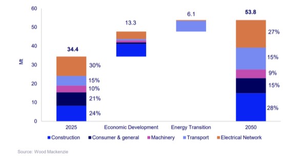
|
24.2.3.2 Precious Metal Residue
The concentrate leach facility would also produce a precious metal residue, containing important silver, gold and sulfur value.
This product is expected to be sold to a combination of offshore and domestic smelters and roasters.
24.2.3.3 Concentrate Leach Facility Economics
This section presents the key financial indicators of the Extension Case with the addition of a CLF as described above. The economics assume a 10% COMEX premium, construction of the CLF after the expansion of the concentrator to 90kstpd, and to a small extent CLF feed from third-party sources in the last 7 years of the 37-year mine life. Based on the Cash Flow Model results, the addition of a CLF with a 10% COMEX premium could add incremental unlevered after-tax NPV8% and NPV10% of $226M and $116M respectively, an after-tax IRR of 14.4% and a payback period of 7.7 years. The key financial metrics of the Extension Case with the addition of a CLF and a 10% COMEX premium, and sensitivities related to the COMEX premium are summarized in Table 24-5. The CLF may be advanced earlier if market conditions are favourable.
The technical studies for the concentrate leach facility have been done to a pre-feasibility level of engineering.
Table 24-5: Extension Case with Concentrate Leach Facility - Key Metrics of the Financial Analysis
| SUMMARY OF KEY METRICS (Assumes 10% COMEX premium) | ||
| Valuation Metrics (Unlevered)1 | Unit | Extension Case with CLF |
| Incremental NPV to extension case @ 8% | $ millions | $226 |
| Incremental NPV to extension case, at project sanction @ 8% | $ millions | $377 |
| Internal rate of return | % | 14.4% |
| Payback period2 | # years | 7.7 |
| Project Metrics | Unit | Extension Case with CLF |
| Growth Capital - Concentrator Leach Facility | $ millions | $703 |
| Production | Unit | Y6 to LOM |
| Copper in concentrate (annual avg.) | 000 tonnes | 23 |
| Copper in cathode (annual avg.)3 | 000 tonnes | 76 |
| Copper - total (annual avg.) | 000 tonnes | 98 |
| Gold (annual avg.)4 | 000 oz | 13 |
| Silver (annual avg.)4 | 000 oz | 2,392 |
| Sulfuric acid (annual avg.) | 000 tonnes | 374 |
| Processing costs | Unit | Y6 to LOM |
| Processing costs - Concentrator | $/t Ore Milled | 6.37 |
| Processing costs - CLF and acid plant | $/t Conc Processed | 288.76 |
| Operating Metrics | Unit | Y6 to LOM |
| Incremental EBITDA to extension case (annual avg.)5 | $ millions | 100 |
Notes: 1. Calculated assuming the following long-term commodity prices: copper price of $5.00 per pound, gold stream price of $540 per ounce, silver stream price of $6.75 per ounce, and molybdenum price of $17.50 per pound. Reflects the terms of the amended Wheaton Precious Metals stream agreement. Includes an upfront deposit of $230 million in the first year of construction in exchange for the delivery of 92.5% of gold and silver contained in the mineral products produced from the Project (other than any gold production that is less than 1g/t in concentrate during the first four years of operation), followed by an additional deposit of up to $70 million upon successful completion of the concentrator expansion to 90,000 short tons per day by the fifth anniversary of commercial production (provided that a reduced contingent payment will nonetheless be payable if such expansion is completed by the tenth anniversary of commercial production). 2. Payback period does not include filtered tailings capital in Years 10 and 11. 3. Copper in cathode production includes purchased concentrate. 4. Gold and silver production include gold and silver contained in concentrate sold and precious metal residue 5. Copper production includes copper contained in concentrate sold. 6. EBITDA is a non-GAAP financial performance measure with no standardized definition under IFRS. For further information, please refer to the company's most recent Management's Discussion and Analysis for the three and six months ended June 30, 2026. 7. By-product credits calculated using amortization of deferred revenue for gold and silver stream sales as per the company's approach in its quarterly financial reporting. Sustaining cash cost includes sustaining capital expenditures and royalties. Cash cost and sustaining cash cost are non-GAAP financial performance measures with no standardized definition under IFRS. For further information, please refer to the Company's most recent Management's Discussion and Analysis for the three and six months ended June 30, 2026.
|
Table 24-6: Extension Case with Concentrate Leach Facility - Sensitivity Analysis
| Sensitivity Analysis - Extension Case with CLF | |||||
| COMEX Premium | Unit | 5% | 10% | 15% | 30% |
| Incremental NPV to Extension Case @ 8% | $ millions | $16 | $226 | $435 | $1,059 |
| Incremental NPV to Extension Case @ 10% | $ millions | ($37) | $116 | $267 | $719 |
| Incremental NPV to Extension Case, at project sanction @ 8% | $ millions | $30 | $377 | $722 | $1,750 |
| Incremental NPV to Extension Case, at project sanction @ 10% | $ millions | ($66) | $217 | $498 | $1,338 |
| Internal rate of return of Extension Case with CLF1 | % | 8.6% | 14.4% | 19.8% | 35.5% |
| Payback period of CLF | # years | 11.6 | 7.7 | 5.9 | 3.9 |
| Incremental EBITDA to extension case (annual avg.) | $ millions | $58 | $100 | $142 | $267 |
Notes: 1. Net present value and internal rate of return are shown on an after-tax basis. 2. EBITDA is a non-GAAP financial performance measure with no standardized definition under IFRS. For further information, please refer to the company's most recent Management's Discussion and Analysis for the three and six months ended June 30, 2026.
Growth capital cost estimates and the basis of estimates for the CLF are based on the latest PFS that was conducted in parallel to the Copper World Feasibility Study are detailed in Table 24-7 and Table 24-8. The CLF cost estimate includes construction of a copper concentrate leach (Albion) circuit, acid plant and SX/EW plant, along with related common construction, G&A and contingency costs.
Table 24-7: Concentrate Leach Facility - Growth Capital Costs Details
| Metric | Unit | Concentrate Leach Facility |
| Reagents | $M | $22 |
| Plant Services | $M | $1 |
| Acid Plant | $M | $98 |
| Leach Plant (Albion) | $M | $332 |
| Site services and utilities | $M | $2 |
| Common Construction | $M | $82 |
| Other | $M | $92 |
| Contingency | $M | $75 |
| Total | $M | $703 |
Table 24-8: Basis for Concentrate Leach Facility Cost Estimates
| Capital Item | Capital Resource |
| Design Maturity | Overall 10% |
| Civil Works Structural |
42% of quantities have been taken as material quantities based on equipment list, PFS or other |
| Mechanical & Platework | 0% issued to Tender (firm), 80% Budget, 20% Historical, Platework is factored based on mechanical equipment |
|
| Capital Item | Capital Resource |
| Piping | Factored based on mechanical equipment |
| Electrical & Instrumentation | 50% of equipment budgetary, andbulks factored based on mechanical equipment |
| Indirects | 8% of directs |
| IPD | 135% of directs |
| Contingency | 12% of total project costs |
24.2.3.4 Marketing Assumptions
The commercial terms assumed for sulfur concentrate, molten sulfur and sulfuric acid reflect engagement with various analysts and market participants, and are considered appropriate given the stage of the project.
|
25 INTERPRETATIONS AND CONCLUSIONS
25.1 Recent History of the Project
Hudbay previously completed a Pre-Feasibility Study for the joint development plan of all the deposits at Copper World within the perimeter of the lands requiring only state and local permits and published the results in its 2023 Technical Report of the Copper World project. The 2023 PFS contemplated a 20-year mine life with a 60 kstpd flotation plant and a copper concentrate leach facility addition in Year 5 of the project while waste and conventional tailings were disposed with the limits of the currently permitted areas.
Since the 2023 PFS was published, Hudbay has conducted extensive new metallurgical testing work, as well as a Feasibility Study for the initial construction of the 60 kstpd flotation plant and all the associated infrastructures required for the construction and operation of the facility. In addition, three pre-feasibility studies were also completed to address the addition of an IPCC system in Year 4, an expansion of the flotation plant to 90 kstpd in Year 5, both of which are included in the Base Case economic evaluation of the Project, as well as the potential addition of a concentrate leach facility, which is not included in the Base Case economic evaluation of the Project.
This Technical Report describes Base Case mine plan, as well as the operating cost and capital cost estimates and economic analysis supporting the Base Case and the methodology and assumptions used in support of the mineral resource and mineral reserve estimates update.
In addition, an Extension Case including the extension of mining activities on Federal land starting in Year 10 is also presented in this report to illustrate the full potential of the project albeit still limited to only including the current measured and indicated mineral resource estimates for the Project. There is additional potential to further expand the mine life and/or increase the production capacity beyond 90 sktpd at a later date than the two scenarios presented in this Technical Report when the inferred mineral resource estimates and the exploration potential of the property will be further confirmed in future studies.
25.2 Open Pit Mining
In the Base Case, the mining sequence considers the exploitation of the pits and their associated infrastructure over a footprint expected to require only state and local permits for 15 years (plus two years of pre-stripping). During this period, all waste, tailings, and low-grade stockpiles are also disposed of within the perimeter of Hudbay's private land properties.
In this Base Case, 390 million tonnes of concentrator feed and approximately 589 million tonnes of waste will be extracted, yielding a life of mine stripping ratio of 1.5 (including pre-stripping material).
An important constraint on the mine production schedule is the limited space for disposing of waste rocks, tailings, and low-grade stockpiles, resulting in a sub-optimum mining sequence from a strict economic standpoint. However, the current mine plan allows the mine to operate in a sustainable manner for 15 years. Securing Federal permits earlier would unlock significant benefits to the project by removing these important constraints on the mining schedule and likely allow more tons and/or better grades to be mined earlier than currently planned. This is illustrated in the Extension Case which has assumed that mining activities could progress onto Federal land in Year 10.
|
25.3 Metallurgy & Processing
The mill consists of conventional crushing, grinding, flotation, molybdenum separation, concentrate dewatering and tailings dewatering.
Comprehensive metallurgical testwork completed across four major campaigns demonstrates that the proposed process flowsheet for the Copper World Project is strong across the evaluated ore domains and variability suites.
• Comminution and Throughput: Ore hardness parameters are thoroughly characterized across all deposits using industry-standard testing indices. Incorporating Random Forest machine learning models that link geochemical assays to hardness metrics directly into the resource block model enables high-confidence throughput forecasting and optimized mill sizing for both the initial 60 kstpd phase and the 90 kstpd expansion.
• Flotation Protocol and Recovery: A flexible flotation protocol has been established to treat all expected ore types across the Project. Key operational parameters include a primary grind P80 of 150 µm, sulfidization using NaHS (-300 mV SIE), dual collectors (SIBX + AERO 3894), and a cleaner dispersant (NS1162) to aid in the rejection of entrained slimes. Active pyrite depression using lime and sodium cyanide (NaCN) is required only when processing high-pyrite ore (e.g. West Pit).
• Concentrate Quality and Penalty Management: The Project produces a clean, marketable copper concentrate averaging approximately 24 % Cu over the life of mine, accompanied by payable precious metals credits. Standard penalty elements (As, Bi, Pb, Zn, Hg) remain below smelter penalty thresholds. Fluorine is the primary deleterious element requiring active process management; testwork suggests that fluorine reports to concentrate largely through mechanical entrainment rather than mineralogical locking or true flotation, validating the selection of low-entrainment Jameson Cells to maintain low fluorine levels in the final concentrate.
• Tailings Dewatering and Disposal: A dual-phase tailings management plan-transitioning from conventional hydraulic disposal (cyclone sand embankment raises and slimes thickening) to having a portion of whole tailings pressure filtered for dry stacking- has been validated and defined with robust engineering design criteria.
• Concentrate Leaching: Testing confirmed that copper concentrates are highly amenable to atmospheric oxidative leaching via the Albion Process™, achieving 97% to 99% copper extraction within 36 to 48 hours (although this is not currently included in either the Base Case or Extension Case).
25.4 Environmental Studies, Permitting, & Social or Community Impact
Studies and surveys that have been completed for the Project include cultural and biological surveys for all the affected areas. Geochemical, groundwater and surface water studies have also been performed in support of design and permitting.
|
The Base Case is expected to require only state, county, and local permits and/or authorizations. All of the major permits required to construct and bring the Base Case into operation have been obtained; provided, however, the IPCC and concentrator expansion to 90 kstpd require permit amendments not yet obtained.
Hudbay is committed to the preservation of historical and cultural resources as well as the protection of endangered and other protected species.
The Project will also bring significant benefits for the local stakeholders. The net economic impact of the Project is estimated at $1,126M for the Base Case, considering only total U.S. taxes over the life of mine, including $200M to the State of Arizona and $362M in local property taxes. It is anticipated to generate over 750 construction jobs, 500 permanent operating roles, and up to 3,000 indirect employment opportunities within Arizona.
25.5 Economic Analysis
Based on the Cash Flow Model results, the Base Case has an unlevered after-tax NPV8% and NPV10% of $1,241M and $845M respectively, an after-tax IRR of 16.8%, a payback period of 5.4 years (including investment in the molybdenum processing plant in Year 1, the IPCC in Year 3 and concentrator expansion to 90 kstpd in Year 4), and an annual average EBITDA of $566M at a long-term copper price of $5.00/lb of copper.
The Extension Case has an unlevered after-tax NPV8% and NPV10% of $2,510M and $1,685M respectively, an after-tax IRR of 18.8%, a payback period of 5.4 years (including investment in the molybdenum processing plant in Year 1, the IPCC in Year 3, concentrator expansion to 90 kstpd in Year 4), and an annual average EBITDA of $522M at a long-term copper price of $5.00/lb of copper. Annual EBITDA is higher in the first 20 years, averaging $684M. The Extension Case is based on measured and indicated mineral resources that are not mineral reserves, which do not have demonstrated economic viability, and is not the selected development option.
25.6 Risks & Uncertainties
The 2026 Definitive Feasibility Study contains several assumptions and expectations that constitute forward-looking information within the meaning of applicable Canadian and United States securities legislation. Such assumptions and expectations are subject to certain risks and uncertainties and include, but are not limited to, Hudbay's expectations with respect to the cost, permitting requirements and design of the Project, the technical and economic viability of the Project, the sale of mineral products from the Project, legal challenges or disputes with respect to the Project, and the potential to advance and further improve the Project.
The following is a discussion of some of the key risks and uncertainties that specifically relate to the 2026 Definitive Feasibility Study. The list below is not an exhaustive list and reference should be made to the cautionary statements at the beginning of this Technical Report, the other risks discussed elsewhere in this Technical Report and Hudbay's public disclosure.
• Federal Lands Extension in Extension Case - A possible extension of the mine activities at the Project onto federal lands is presented in Sections 21, 22, 24 and 25 of this Technical Report as an Extension Case. The Extension Case is presented in this Technical Report to illustrate the long-term potential of the Project and future growth opportunities. Any such expansion would be subject to a federal permitting process under NEPA. The ability to obtain such federal permits on the desired timelines (or at all) cannot be guaranteed and may be impacted by community opposition (including by Pima County) and/or litigation by those who oppose the Project.
|
• Permitting - As noted in Section 20.2 of this Technical Report, Hudbay has received the key state permits required to bring the Base Case into production. This includes the Air Quality Permit that was received on January 2, 2025 from the ADEQ following a robust process, including a public comment period that concluded in the third quarter of 2024. The Arizona Office of Administrative Hearings and Arizona Superior Court have upheld the ADEQ's decision to issue the Air Quality Permit following appeals. In addition, a right of way as well as a purchase of certain state lands are currently under legal challenge and an adverse decision in such litigation could have a negative impact on the Project design or schedule. Hudbay remains confident that its state permits (including the Air Quality Permit), and the rights of way and other authorizations received for the Copper World project, will continue to be upheld, notwithstanding further potential appeals or challenges that may take place, however, there can be no assurance in this regard. There is a risk that authorizations related to federal or state lands that we have obtained, or may require in the future, could be subject to similar challenges or appeals and could impact our mine plan and development timelines.
• Capital Cost Expectations - A significant amount of capital is required to construct and operate the Project. Capital costs may increase due to a variety of factors, including inflationary pressures, project scope changes, supply chain constraints, cross-border tariffs on construction materials and consumables and general cost escalation common to mining projects globally. A description and summary of the current projected Base Case Capital Costs, Growth Capital Costs and Extension Case Capital Costs are included in this Technical Report and, in the future, any such cost expectations could change such that the Project will require the expenditure of additional funds in order to commence or maintain operations in accordance with the mine plan. Any increase to the capital costs forecasted in this Technical Report could have an adverse effect on the Project economics.
• Stream Payments - As described in this Technical Report, Hudbay BVI is entitled to receive an initial deposit from Wheaton of $230M (subject to the satisfaction of certain conditions) against delivery of 92.5% of the gold and silver contained in the mineral products produced from the Project (other than any gold production that is less than 1g/t in concentrate during the first four years of operation), at fixed gold and silver prices of 15% of the market price. In addition, a contingent payment of up to $70M is payable by Wheaton to Hudbay BVI upon completion of the concentrator expansion to 90 kstpd by the fifth anniversary of commercial production, provided that a reduced contingent payment will nonetheless be payable if such expansion is completed by the tenth anniversary of commercial production. The economic model in this Technical Report assumes Copper World LLC will receive an upfront deposit of $230M in the first year of construction and an additional deposit of $70M in Year 5 of commercial production, but there can be no certainty that such payments are made by Wheaton and received by Hudbay BVI on the expected timelines or that the conditions required to be satisfied in order to trigger such payments will be successfully completed in a timely manner or at all.
• Water Availability - The Project could be susceptible to water availability risks in the future, including those caused by climate change or declining basins. Water scarcity could lead to pressure and government action to reduce industrial water consumption, which may restrict the use of existing water rights (including Copper World's water permit). As a result, water availability for the Project may be affected by seasonal variability, competing users, regulatory restrictions, or infrastructure limitations. Such challenges, in addition to any changes in applicable water laws or regulations, could adversely affect the ability to source, manage, treat or discharge water, and, therefore, could adversely affect production or costs related to the Project.
|
26 RECOMMENDATIONS
26.1 Drilling & Resource Modelling Updates
As part of an industry standard operational readiness and pre-production plan, proceed with Infill & Definition Drilling: in all deposits prior to initial production to further confirm grade continuity and upgrade remaining Inferred resources to Measured and Indicated categories.
Continue updating the Random Forest machine learning block models with assay data received after Feasibility Study, operational sampling data to refine site-wide predictions for ore hardness, talc, swelling clays, and copper deportment.
Validate and adjust as needed the short-term and long-term resource modelling approach based on reserve to mill reconciliation when production starts.
26.2 Mine Operations
To further optimize mine design and de-risk early mine life operations, the following is recommended:
• Finalize Waste Sequence Sensitivity Analysis: Tactical short-term planning scenarios should be leveraged to dynamically optimize and adjust the in-pit waste disposal sequence to handle potential backfill/phase delays.
• Targeted Geotechnical Investigation: Execute targeted post-FS geotechnical site investigations to address remaining data gaps. This includes characterization of Gila formation cementation, historical geomechanical database correlations, and specific foundation bearing capacities at the IPCC location.
• Continuous, Targeted Monitoring to Maintain Pit Stability: Implement a monitoring program to track rock mass behaviour during excavation, allowing mine design to be adjusted or stabilization measures to implemented during operation.
Complete final engineering and pit-backfill sequencing required to commission the 100 kstpd primary gyratory IPCC system in the East Pit by Year 4/5, significantly reducing emissions and long-term haulage costs.
Finalize operational readiness and safety protocols for deploying 320-ton Autonomous Haulage System (AHS) Caterpillar 794 trucks and high-capacity hydraulic shovels.
26.3 Metallurgy & Processing
To further optimize processing performance, refine operational controls, and de-risk early mine life operations, the following is recommended:
|
• Mine Plan Optimization for Comminution: Evaluate detailed mine plan integration and scheduling strategies to smooth or minimize peak hardness criteria during the 90 kstpd expansion phase. Mitigating localized hardness spikes will reduce installed comminution power requirements, directly lowering expansion capital expenditures.
• Targeted Ramp-Up Testwork: Execute targeted comminution, quantitative mineralogy, and flotation testwork on the specific ore blocks scheduled for mill feed during the initial 12- to 24-month commissioning and ramp-up period to establish precise operational control strategies prior to plant start-up.
• Geometallurgical Ore Blending Framework: Establish an advanced ore blending protocol driven by block model predictive outputs. Operational blending strategies should be tailored to proactively mitigate dynamic thickening and flotation upsets caused by localized surges of swelling clays (e.g., smectite/montmorillonite), elevated talc content, or highly reactive pyrite.
• Ore Stockpiling and Weathering Characterization: Perform controlled stockpiling and aging testwork to quantify and mitigate potential oxidation effects-such as surface tarnishing or secondary copper dissolution-on ore stored in run-of-mine (ROM) stockpiles prior to processing.
• Detailed Fluorine Deportment Mapping: Complete ongoing Electron Microprobe Analysis (EPMA) to quantitatively map mineralogical fluorine deportment, explicitly differentiating between entrained mica/fluorite/apatite and lattice-bound fluorine in complex silicates like talc.
• Copper-Molybdenum Separation Optimization: Conduct additional Cu/Mo separation testwork on bulk concentrate derived from multiple ore domains to optimize Mo flotation strategies.
• Concentrate Dewatering Validation: Complete physical bench-scale thickening and filtration testing on final copper concentrate samples to replace current benchmark assumptions with empirical design criteria.
26.4 Water and Tailings
Execute phase plans to transition from initial conventional hydraulic tailings deposition to filtered tailings for approximately one-third of total tailings volume starting in Year 5.
Optimize process water recovery from tailings thickener overflow and site stormwater management ponds to stay within the permitted 6,000 acre-feet/year groundwater withdrawal limit from the Santa Cruz Basin.
26.5 Permits
Prepare for submission of permit amendments to allow for mill expansion, IPCC and other permit modifications as needed, after the mine enters operation.
Continue to expedite the power supply agreement to maintain targeted energization dates.
|
27 REFERENCES
ADEQ, 2004. Arizona Mining Guidance Manual BADCT, ADEQ, 2004, Publication # TB 04-01.
Amelunxen, P., et al., 2018. A Phenomenological Model of Entrainment and Froth Recovery for Interpreting Laboratory Flotation Kinetics Tests. Miner. Eng. 125, 60-65.
Amelunxen, P., Ladouceur, R., 2019. "Applied Flotation Modeling." In: Dunne, R.C., Kawatra, S.K., Young, C.A. (Eds.), SME Mineral Processing & Extractive Metallurgy Handbook. Society for Mining, Metallurgy and Exploration Inc., 1053-65.
Amelunxen, R., Amelunxen, P., 2013. Aminpro's Methodology for Executing and Interpreting Laboratory Batch Kinetics Tests (Part 1 of 2). VIII Meeting of the Southern Hemisphere on Mineral Technology. Goiania, GO., Brasil, 2013.
AMinpro, 2023. Metallurgical Testwork Program for Copper World Project by Hudbay Minerals.
Anzalone, S., 1995. The Helvetia Area Porphyry Systems, Pima County, Arizona. In: Pierce, F.W. &. Bolm, J.G. ed. Porphyry Copper Deposits of the American Cordillera: Arizona Geological Society Digest 20.
Augusta Resource Corp., 2012. NI 43-101 Technical Report: Updated Feasibility Study, Pima County, Arizona USA.
Barra, F., Ruiz, J., Valencia, V.A., Ochoa-Landin, L., Chesley, J.T., &. Zurcher, L., 2005. Laramide porphyry Cu-Mo mineralization in northern Mexico: Age constraints from Re-Os geochronology in molybdenite. Economic Geology, 100(8), pp. 1605-1616.
Barrat, D.J., 1979. Semi-Autogenous Grinding: A Comparison with the Conventional Route. CIM Bulletin.
Base Met Lab, 2016. Phase II Metallurgical Testing for the Rosemont Copper Project, BL0076.
Base Met Lab, 2016. Verification of Rosemont Process Parameters, BL0065.
Blue Coast Research, 2023. Copper World Met Testwork Program.
Bray, J. & Travasarou, T., 2007. Simplified Procedure for Estimating Earthquake-Induced Deviatoric Slope Displacements. Journal of Geotechncal & Geoenvironmental Engineering, 133(4), pp. 381-392.
Briggs, D.F., 2014. History of Helvetia-Rosemont Mining District, Pima County, Arizona. Arizona Daily Independent, 15-17 March.
Briggs, D.F., 2020. Helvetia-Rosemont, Arizona's Hardscrabble Mining Camp. Contributed Report CR-20-A:Arizona Geologic Survey.
Bulatovic, S.M., 2007. Handbook of Flotation Reagents: Chemistry, Theory and Practice: Volume 1: Flotation of Sulfide Ores. Elsevier.
|
Call & Nicholas, Inc. (CNI), January 2016. 2015 Pit Slope Feasibility Evaluation For The Rosemont Deposit: Revision 02.
Cappuccitti, F. and Nesset, J.E. 2009. Frother and collector effects on flotation cell hydrodynamics and their implication on circuit performance. Proceedings of the 41st Annual Canadian Mineral Processors Conference (CMP), Ottawa, Canada.
Cappuccitti, F., 2008. Frother optimization in industrial flotation circuits. Proceedings of the 40th Annual Canadian Mineral Processors Conference (CMP), Ottawa, Canada.
CIM, 2011. NI 43-101 Standards of Disclosure for Mineral Projects, Form 43-101F1 Technical Report and Related Consequential Amendments. [Online] Available at: https://mrmr.cim.org/media/1017/national-instrument-43-101.pdf. [Accessed 5 May 2023].
CIM, 2014. Definition Standards for Mineral Resources & Mineral Reserves. [Online] Available at: https://mrmr.cim.org/media/1128/cim-definition-standards_2014.pdf. [Accessed 5 May 2023].
CIM, 2019. Estimation of Mineral Resources & Mineral Reserves Best Practice Guidelines. [Online] Available at: https://mrmr.cim.org/media/1146/cim-mrmr-bp-guidelines_2019_may2022.pdf [Accessed 5 May 2023].
Cracknell, M.J., 2014. Machine learning for geological mapping: Algorithms and applications: Ph.D. thesis, University of Tasmania.
Drewes, H., 1971. "Miscellaneous Geologic Investigations MAP I-613: Geologic Map of the Sahuarita Quadrangle, Southeast of Tucson, Pima, County, Arizona: United States Geologic Survey.
EWP-0000-PM-RPT-0001 Pre-feasibility Study - Copper World Project Ex-Pit Crushing and Conveying, DRA, 2026.
EWP1-0000-PM-RPT-0001 Feasibility Study - Copper World Project, DRA, 2026.
EWP7-0000-PM-RPT-0001 Pre-feasibility Study - Copper Project Process Plant Expansion, DRA, 2026.
Finch, J.A., Nesset, J.E. and Acuña, C., 2008. Role of frother in bubble generation and froth stability. Minerals Engineering, 21(12-14), 949-957.
Glencore Technology, 2022. Personal Communication.
Glencore Technology, 2023. Hudbay Minerals Albion Process Plant Testwork Report: Copper World Project. PA00042-GT-RPT0001.
Glencore Technology, 2026. Hudbay Minerals Copper World Copper Concentrate Leaching Albion Process Plant Testwork and Engineering Study Report, PA00042-GTS-RPT00003.
Hudbay Minerals Inc., 2017. NI 43-101 Technical Report - Feasibility Study: Updated Mineral Resource, Mineral Reserve and Financial Estimates, Rosemont Project, Pima County, Arizona USA.
Hudbay Minerals Inc., 2017. NI 43-101 Technical Report, Feasibility Study, Updated Mineral Resource, Mineral Reserve and Financial Estimates, Rosemont Project, Pima County, Arizona, USA.
|
Hudbay Minerals Inc., 2022. NI 43-101 Technical Report, Preliminary Economic Assessment, Copper World Complex, Pima County, Arizona, USA.
Hudbay Minerals Inc., 2022. Preliminary Economic Assessment: Copper World Complex, Pima County, Arizona USA.
Hudbay Minerals Inc., 2023. NI 43-101 Technical Report, Phase I Pre-Feasibility Study and Updated Mineral Resource Estimates, Copper World Complex, Pima County, Arizona, USA.
In the underlying metallurgical report (Kappes, Cassiday & Associates, 2022), these samples were designated by pit name followed by "Composite" (e.g., "Peach Composite"). To avoid confusion, they have been renamed in this report with the suffix "PEA"-or "Transitional" for Broad Top and East, where samples represented transitional zone material rather than the entire pits.
ISRM, 1985. Suggested Method for Determining Point Load Strength. In: The Complete ISRM Suggested Methods for Rock Characterization, Testing and Monitoring: 1974-2006.
Kappes, Cassiday & Associates, 2022. Rosemont Project, Composite Column and Flotation Test Work, Report of Metallurgical Test Work.
Kappes, Cassiday & Associates, 2022. Rosemont Project, Variability Samples, Report of Metallurgical Test Work.
Kermack, K.A. & Haldane, J.B.S., 1950. Organic Correlation and Allometry. Biometrika, 37(1/2), pp. 30-41.
Laboratorio Metallurgico Chapi, 2022. Grinding Testing on 60 Samples.
Laskowski, J.S., 2003. Testing flotation frothers. Progress in Mineral Processing / Physicochemical Problems of Mineral Processing, 37, 13-22.
Lotter N.O. and Bradshaw, D.J., 2010. The formulation and use of Mixed Collectors in Sulfide Flotation. Minerals Engineering, 23(11-13), 945-951.
Lotter N.O. and Bradshaw, D.J., 2010. The formulation and use of Mixed Collectors in Sulfide Flotation. Minerals Engineering, 23(11-13), 945-951.
Lotter N.O. and Bradshaw, D.J., 2018. The Formulation and Use of Mixed Collectors in Sulfide Flotation-Valuable Performance Gains. Extraction 2018: Proceedings of the First Global Conference on Extractive Metallurgy.
Lotter N.O. and Bradshaw, D.J., 2018. The Formulation and Use of Mixed Collectors in Sulfide Flotation-Valuable Performance Gains. Extraction 2018: Proceedings of the First Global Conference on Extractive Metallurgy.
M3 Engineering and Technology Corporation, 2007. NI 43-101 Technical Report for the Rosemont Copper Project, Feasibility Study, Pima County, Arizona, USA.: Prepared for: Augusta Resource Corporation.
M3 Engineering and Technology Corporation, 2007. NI 43-101 Technical Report for the Rosemont Copper Project, Feasibility Study, Pima County, Arizona, USA. Prepared for: Augusta Resource Corporation.
|
M3 Engineering and Technology Corporation, 2009. NI 43-101 Technical Report for the Rosemont Copper Project, Updated Feasibility Study, Pima County, Arizona, USA.: Prepared for: Augusta Resource Corporation.
M3 Engineering and Technology Corporation, 2009. NI 43-101 Technical Report for the Rosemont Copper Project, Updated Feasibility Study, Pima County, Arizona, USA. Prepared for: Augusta Resource Corporation.
M3 Engineering and Technology Corporation, 2012. Rosemont Copper Project: NI 43-101 Technical Report, Updated Feasibility Study, Pima County, Arizona, USA.: Prepared for Augusta Resource Corporation.
M3 Engineering and Technology Corporation, 2012. Rosemont Copper Project, NI 43-101 Technical Report, Updated Feasibility Study, Pima County, Arizona, USA. Prepared for: Augusta Resource Corporation.
Maher, D.J., 2008. Reconstruction of middle Tertiary extension and Laramide porphyry copper systems, east-central Arizona, University of Arizona: Unpublished Ph. D. Diss. thesis.
Parrish, I., 1997. Geologist's Gordon Knot: to cut or not to cut. Mining Engineering Journal, pp. 45-49.
Piteau Associates, 2022. Rosemont Copper World Project Hydrological Characterization.
Piteau Associates, 2023. Copper World Complex Project Operational Closure and Water Management Study.
Ramussen, J., Hoag, C., & Horstman, K., 2012. Geology of the Northern Santa Rita Mountains, Arizona, Fall Field Trip September 15, 2012: Arizona Geological Society.
SGS Canada Inc., 2015. The Grindability Characteristics of Samples from the Rosemont Deposit, Project 14816-001 - Final Report.
SGS Canada Inc., 2022. An Investigation into the Grindability Characteristics of Thirteen Samples From the Rosemont Project, Project 18329-04.
SGS Canada Inc., 2023. An Investigation into Grindability and POX Testwork, Project 19424-01A.
Simón, A., 2004. Evaluation of Twin and Duplicate Samples: The Hyperbolic Method., Internal document: AMEC Perú Ltda.
Tailpro Consulting, 2023. Copper World Complex Technical Report: Tailings Cycloning, Thickening and Deposition.
Tailpro Consulting, 2023. Copper World Complex Technical Report: Tailings Cycloning, Thickening and Deposition.
Tailpro Consulting, 2025. Copper World Complex Technical Report: Tailings Cycloning, Thickening and Deposition.
Tailpro Consulting, 2025. Copper World Complex Technical Report: Tailings Cycloning, Thickening and Deposition.
Wood Mackenzie, 2023. Global Copper Strategic Planning Outlook - Q2 2023.
Wood, 2022. Site Water Management Plan.
XPS Consulting & Testwork Services, 2015. Rosemont Project Phase II Metallurgical Testwork.